FoxESS LV5200 User manual

In order to prevent improper operation before use, please carefully read this
manual.
LV5200

Table of Contents
1. Introduction ................................................................................................................ 1
2. Symbols ..................................................................................................................... 1
3. Safety ......................................................................................................................... 2
3.1 Handling ............................................................................................................ 2
3.2 Installation ......................................................................................................... 2
3.3 Response to Emergency Situations ................................................................. 2
3.4 Warning Labels ................................................................................................. 3
4. Product Information ................................................................................................... 4
4.1 Battery Module Specifications .......................................................................... 4
4.2 Battery Charge/discharge Curve ...................................................................... 5
5. Product Features ....................................................................................................... 5
5.1 Battery System Features .................................................................................. 5
6. Installation .................................................................................................................. 7
6.1 Items in the package ......................................................................................... 7
6.2 Clearance .......................................................................................................... 8
6.3 Tools ................................................................................................................. 8
6.4 Installation Steps .............................................................................................. 9
6.5 System Start up .............................................................................................. 11
7. Commissioning......................................................................................................... 12
8. Exclusion .................................................................................................................. 13
9. Troubleshooting and Maintenance .......................................................................... 13
9.1 Maintenance ................................................................................................... 13
9.2 Troubleshooting .............................................................................................. 13

1
1. Introduction
The document describes the installation, commissioning, maintenance and troubleshooting of the
following low voltage battery listed below.
LV5200
Note: 5200 = 5.2kWh Low Voltage
The battery chemistry of this product is Lithium Iron Phosphate. This manual is designed for qualified
personnel only. The tasks described in this document should be performed by authorized and qualified
technicians only.
After Installation the Installer must explain the user manual to the end user.
2. Symbols
Caution, risk of electric shock.
Do not place nor install near flammable or explosive materials.
Install the product out of reach of children.
Read the instruction manual before starting installation and operation.
Do not dispose of the product with household wastes.
Recyclable.
Disconnect the equipment before carrying out maintenance or repair.
Observe precautions for handling electrostatic discharge sensitive devices.
Protective Class 1.
Caution, risk of electric shock, energy storage timed discharge.

2
3. Safety
Any work on the Batteries should be handled by authorized technicians and hence it is understood that
the technicians should familiarize themselves with the contents of this manual before any maintenance or
installation is carried out on the system.
3.1 Handling
· Do not expose battery to open flame.
· Do not place the product under direct sunlight.
· Do not place the product near flammable materials. It may lead to fire or explosion in case of
accident.
· Store in a cool and dry place with ample ventilation.
· Do not store the product near water sources.
· Store the product on a flat surface.
· Store the product out of reach of children and animals.
· Do not damage the unit by dropping, deforming, impacting, cutting or penetrating with a sharp
object. It may cause leakage of electrolyte or fire.
· Do not touch any liquid spilled from the product. There is a risk of electric shock or damage to skin.
· Always handle the battery wearing the insulated gloves.
· Do not step on the product or place any foreign objects on it. This can result in damage.
· Do not charge or discharge damaged battery.
· Do not store the battery near water sources.
3.2 Installation
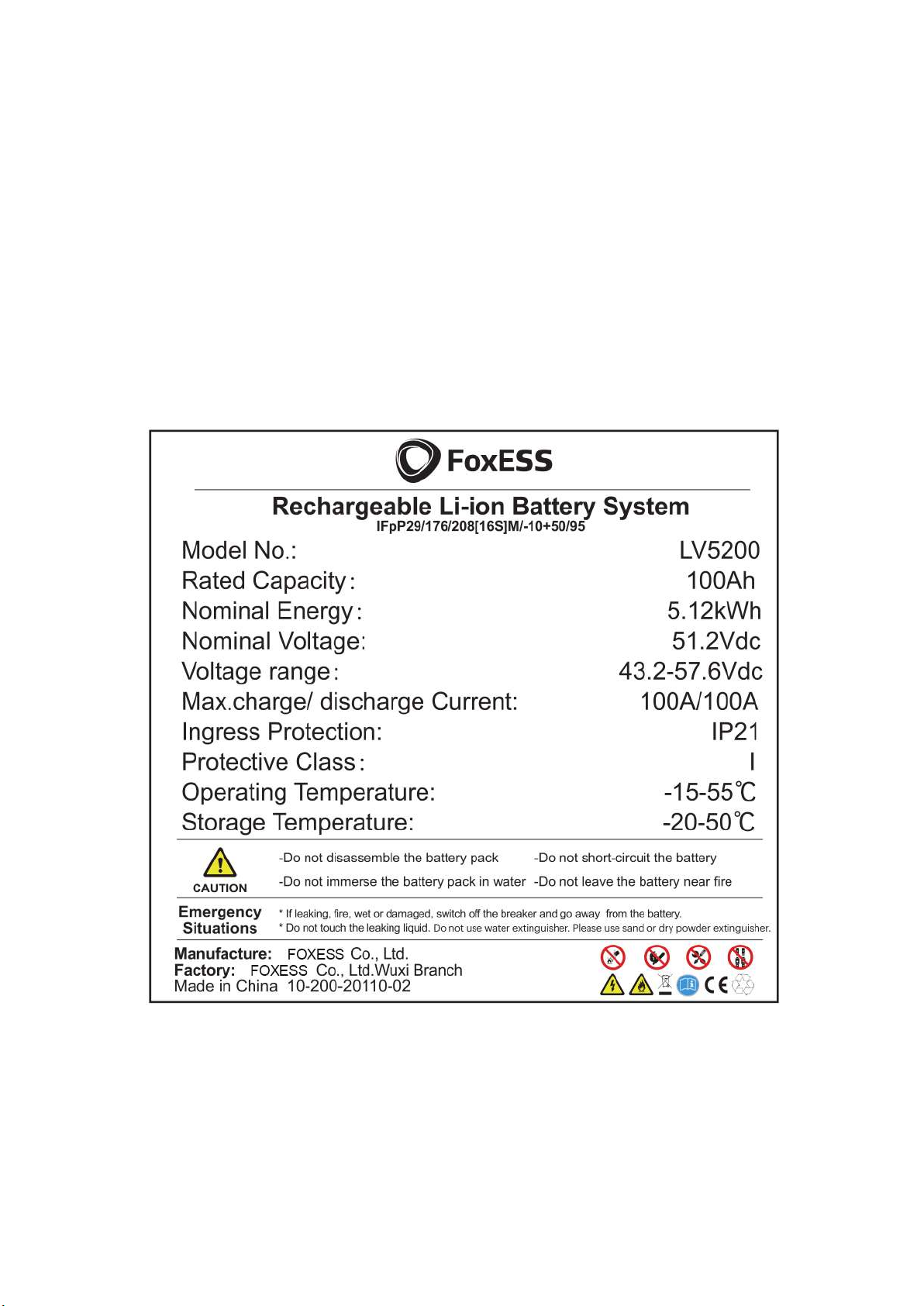
· Do not connect the LV5200 to inverter conductors or Photo-Voltaic conductors. This will damage
the battery and may result in explosion.
· After unpacking, please check the product for damages and missing parts.
· Make sure that the inverter and battery is completely turned off before commencing installation.
· Do not interchange the positive and negative terminals of the battery.
· Ensure that there is no short circuit of the terminals or with any external device.
· Do not exceed the battery voltage rating of the inverter.
· Do not connect the battery to any incompatible inverter.
· Do not connect different battery types together.
· Please ensure that all the batteries are grounded properly.
· Do not open the battery to repair or disassemble. Only manufacturer is allowed to carry out any
such repairs.
· In case of fire, use only dry powder fire extinguisher. Liquid extinguishers should not be used.
· Install the batteries only inside approved manufacturer enclosure. Installing the battery anywhere
outside is strictly forbidden.
· Do not install the battery near water sources or places where the battery can get wet.
· Install the battery away from children or pets.
· Do not use battery in high static environment where the protection device might be damaged.
· Do not install with other batteries or cells.
3.3 Response to Emergency Situations
The battery can be used in single or multi machine in parallel. It is designed to prevent hazards or failures.
However, manufacturer cannot guarantee their absolute safety.
Under exposure to the internal materials of the battery the following recommendations should be carried
out by the user.
· If there has been inhalation, please leave the contaminated area immediately and seek medical
attention.
· If there has been contact with eyes, rinse the eyes with running water for 15 minutes and seek
medical attention immediately.
· If there has been contact with the skin, wash the contacted area with soap thoroughly and seek
medical attention immediately.
· If there has been ingestion, induce vomiting and seek medical attention.

3
Fire Situation
In situations where the battery is on fire, if it is safe to do so, disconnect the battery pack by turning of the
switch to shut off the power to the system. Use FM-200 or Co2 fire extinguisher for the battery and an
ABC fire extinguisher for the other parts of the system.
Under any fire situation, please evacuate the people from the building immediately before trying to
extinguish it.
Water Situation
The battery modules are not water resistant. Hence care should be taken not to get it wet. If you find the
battery completely or partially submerged in water do not try to open. Contact authorized personnel or
manufacturer for further instructions.
3.4 Warning Labels
Warning labels are attached on the battery pack.

4
4. Product Information
LV5200 photovoltaic energy storage system is a 48V energy storage system based on
lithium-ion ferrous phosphate battery. It is equipped with a customized battery management system
(BMS), which is designed for energy storage applications of household photovoltaic power generation
users. In the daytime, the surplus power of photovoltaic power generation can be stored in the battery. At
night or when necessary, the stored energy can be provided to the electrical equipment, it can improve
the use efficiency of photovoltaic power generation, peak-load shifting, and provide emergency standby
power.
4.1 Battery Module Specifications
Specifications for Battery
N
ote
Battery module LV5200
Nominal capacity (Ah) 100 0.5C, 25±2°C
Nominal voltage (Vdc) 51.2
Battery voltage range (Vdc) 43.2-57.6
Max. continuous discharging current (A) 100
Max. continuous charging current (A) 100
Recommended charging current (CC-CV) (A)
100
Charging cut off current
(constant current and constant voltage) (A) 5
Peak charging current (30s) (A) 105
Peak discharging current (30s) (A) 150
Cycle life ≥6000@25°C @90% DOD
Storage temperature -20°C - 50°C
Operating temperature range Charge: 0°C - 55°C
Discharge: -15°C - 55°C
Discharge capacity (Ah)
0°C±2 @ 1C @ 80%
25°C±2 @ 1C @ 100%
45°C±2 @ 1C @ 96%
Energy density (wh / kg) 104
Ingress protection IP21
Communication RS485
Weight (kg) 49
Dimensions (L*W*H) (mm) 342*207*600
Lithiumion Battery Module
Model No. LV5200
Nominal capacity 100Ah
Nominal energy 5.12kWh
Nominal voltage 51.2Vdc
Voltage range 43.2-57.6Vdc
Max. charge/discharge current 100A/100A
Ingress protection IP21
Protective class I
Operating temperature - 15°C- 55°C
Storage temperature - 20°C- 50°C

5
4.2 Battery Charge/discharge Curve
5. Product Features
5.1 Battery System Features
The batteries have been fitted with multiple protection systems to ensure the safe operation of the system.
Some of the protection system includes:
· Inverter interface protection: Over voltage, over current, external short circuit, reverse polarity,
ground fault, over temp, in rush current.
· Battery Protection: Internal short circuit, over voltage, over current, over temp, under voltage.
The battery system contains the following Interface to allow it to connect and operate efficiently.
Battery interface:
Object
Description
Object
Description
A POWER-1 I Reset button
B LinkPort1 J Start switch
C Ground screw K CAN
D ADDR L RS485
E Fastening screw M Ground screw
F SOC LED N LinkPort0
G Alarm LED O POWER-2
H Running LED
0A
50A
100A
150A
200A
Charge Discharge
Normal Standby Protect after 5min Protect after 30s Protect immediately
100
110
100
110
125
150
105

6
Running LED
This LED is used to indicate if the battery is operating effectively. A green light on this LED means the
battery is ON and operating normally.
Alarm LED
This LED is used to indicate if the battery is operating failure. A red light on this LED means the battery is
operating abnormally.
Communication parallel interface (Link Port0, Link Port1, RS485) and communication interface to
inverter (CAN/RS485)
LV5200 has two 485 communication units in series operation, one for master control and one for slave
control.
Network interface description: Link Port0 is connected to the upper battery module, Link Port1 is
connected to the lower battery module. CAN / RS485 is the communication interface to the inverter.
The interface is defined as follows:
Pin configuration is as follows:
- Link Port0
- RS485
Earth Terminal
This terminal is used to connect the battery to the earth for safety purposes.
Handle
The handle is used to carry or move the battery.
Power Terminal
A set of positive and negative terminals to connect the battery to the inverter. When you are unplugging
the wires from the terminals, make sure you press the lock button and then pull it. When installing the
plug, do not press the button and push the plug until you hear a click sound.
In addition to the above physical features, the battery has the following performance:
1. 90% Depth of Discharge;
2. Cycle life >6000 cycles.
Pin
Function
d
efinitions
Function
d
eclarati
on
1 B RS485-B
2 A RS485-A
3 GND GND
4 NC NC
5 NC NC
6 GND GND
7 A RS485-A
8 B RS485-B
Pin
Function
definitions
Function
declarati
on
1 B RS485-B
2 A RS485-A
3 GND GND
4 NC NC
5 NC NC
6 GND GND
7 A RS485-A
8 B RS485-B
- CAN/RS485
Pin
Function
definitions
Function
declarati
on
1 CANH / B
CANH / RS485-B
2 CANL / A CANL / RS485-A
3 GND GND
4 NC NC
5 NC NC
6 GND GND
7 CANL / A CANL / RS485-A
8 CANH / B
CANH / RS485-B
- Link Port1
Pin
Function
definitions
Function
declarati
on
1 B RS485-B
2 A RS485-A
3 GND GND
4 NC NC
5 NC NC
6 GND GND
7 A RS485-A
8 B RS485-B

7
6. Installation
6.1 Items in the package
Please check if following items are including with the package:
Note:
1. Use only the parts included with the battery pack to ensure proper installation. If anything is
damaged or missing, contact manufacturer or your distributor.
2. Object I is provide separately, not including in battery package. Please contact your dealer if you do
not have it.
A B C D E
F G
H I
J K L
Object
Quantity
Description
Object
Quantity
Description
A 1 Low voltage battery
G 1 Communication network cable
B 1 Bracket H 1 Ground wire
C 5 Expansion tubes I 1 Power line (2m)
(Battery to inverter)
D 5 Expansion screws J 1 Network cable (3m)
(Battery to inverter)
E 1 Earth terminal K 1 Installation guide
F 1 Power line (0.5m)
(Battery to battery) L 1 User manual
Installation
Quick
Guide
Manual

8
6.2 Clearance
Make sure to leave a space of at least 30 cm. A clearance of at least 30 cm must be Ieft around the
battery pack for proper cooling.
Note: Make sure that the battery pack is always exposed to the ambient air. The battery pack is cooled by
natural convection. If the battery pack is entirely or partially covered or shielded, it may cause the battery
pack to stop operating.
6.3 Tools
The following tools will be required to install the battery.
Screw driver Crimping modular Safety shoes
Safety gloves Safety goggles Plier
Spanner Multimeter Ribbon
Position
M
in
size
Left 30cm
Right 30cm
Top 30cm
Bottom On the ground

9
6.4 Installation Steps
· Mounting
STEP-1
Measure and confirm that the bottom of the bracket is 285mm away from the ground, and mark the 5-hole
positions on the bracket with a pen.
STEP-2
Drill holes with electric drill, make sure the holes are deep enough (at least 50mm) for installation, and then
tighten the expansion tubes.
STEP-3
Install the expansion tubes in the holes, and tighten them. Then install the wall bracket by using the expansion
screws.
STEP-4
Hang the battery over the bracket, move the battery close to it, lower the battery, and make sure the 2 mounting
bars on the back are fixed well with the 2 grooves on the bracket.
· Wiring

10
STEP-1
Connect BAT + and BAT - to POS + and NEG - respectively. Connect the battery communication network
cable to the lithium battery communication port of the inverter.
STEP-2
Plug the power plug into any output socket on the left or right of the battery. Connect the communication
network cable to the CAN interface of the battery, connect the ground terminal of the battery with the
ground wire, and lock the nut.
STEP-3
Plug the power line of the parallel machine into the remaining output socket of the battery, insert the
communication line of the parallel machine into LinkPort1, and lock the ground nut.
STEP-4
Plug the power line of the parallel machine into the remaining output socket of the battery, insert the
communication line of the parallel machine into LinkPort0, and lock the ground nut.

11
STEP-5
Repeat STEP-3 through STEP-4 to insert more batteries (up to 12 batteries).
6.5 System Start up
· When connected with inverter, the inverter should be turned on first to avoid the current pulse of the
inverter increasing to the battery pack.
· All installation and operation must comply with local electrical standards.
· Check all power cables and communication cables carefully.
1. Turn on the POWER switch
Dial address selection
Definition of dial switch for parallel machine: When the battery pack is connected with multiple machines
in parallel, the dial switch can be used to distinguish different pack addresses. The hardware address can
be set by the dial switch on the board. Addresses 1, 2, 3, and 4 represent the online number of batteries
(only the host needs to be configured), 5, 6, 7, and 8 represent the slave address. The slave address
needs to be continuous, and can support up to 12 batteries in parallel.
Single machine address setting: 0001 0000
Parallel machine address setting: refer to the table below for the definition of dial switch.
For example, three machines are in parallel, and the dial switch example is as follows:
Master dial: 0011 0000, slave 1 dial: 0000 0001, slave 2 dial: 0000 0010
Slave address
Address
Dial switch position Description
ADDR8
ADDR7
ADDR6
ADDR5
3 ON OFF OFF OFF PACK 1
4 OFF ON OFF OFF PACK 2
5 ON ON OFF OFF PACK 3
6 OFF OFF ON OFF PACK 4
7 ON OFF ON OFF PACK 5
8 OFF ON ON OFF PACK 6
9 ON ON ON OFF PACK 7
10 OFF OFF OFF ON PACK 8
11 ON OFF OFF ON PACK 9
12 OFF ON OFF ON PACK 10
13 ON ON OFF ON PACK 11

12
1) Before starting, please dial the code to the corresponding position according to the actual number of
parallel machines.
2) After pressing the start switch for 1s, all LEDs will be on and flashing, which indicates that the battery
is started normally. After pressing the reset switch for 3s, the battery will turn on the discharge function.
3) After the communication with the inverter is disconnected for 10s, the battery will turn off the output. If
it does not recover after 10 minutes, the battery will be shut down.
7 Commissioning
There are seven LED indicators on the front of the battery packs to show its operating status.
- Running LED indication
After startup, the running indicator light flashes, which indicates that the equipment is in normal
operation.
- Alarm LED indication
When the battery is in normal operation, the alarm LED is off, and after the fault occurs, the alarm LED is
always on.
- SOC LED indication
Status Charge
Discharge
Stand by
=100%
Light Light
Go off
Light Light
Light Light
Light Light
Light Light
>100%>SOC>=80%
Flash Light
Light Light
Light Light
Light Light
Light Light
80%>SOC>=60%
Go off
Go off
Flash Light
Light Light
Light Light
Light Light
60%>SOC>=40%
Go off
Go off
Go off
Go off
Flash Light
Light Light
Light Light
40%>SOC>=20%
Go off
Go off
Go off
Go off
Go off
Go off
Flash Light
Light Light
20%>SOC>=0
Go off
Go off
Go off
Go off
Go off
Go off
Go off
Go off
Flash Light

13
8 Exclusion
The warranty shall not cover the defects caused by normal wear and tear, inadequate maintenance,
handling, storage faulty repair, modifications to the battery or pack by a third party other than
manufacturer or manufacturer agent, failure to observe the product specification provided herein or
improper use or installation, including but not limited to the following.
· Damage during transport or storage.
· Incorrect Installation of battery into pack or maintenance.
· Use of battery pr pack in inappropriate environment.
· Improper, inadequate, or incorrect charge, discharge or production circuit other than stipulated
herein.
· Incorrect use or inappropriate use.
· Insufficient ventilation.
· Ignoring applicable safety warnings and instructions.
· Altering or attempted repairs y unauthorized personnel.
· In case of force majeure (ex: lightning, storm, flood, fire, earthquake, etc.).
· There are no warranties-implied or express-other than those stipulated herein. manufacturer shall
not be liable for any consequential or indirect damages arising or in connection with the product
specification, battery or pack.
9 Troubleshooting and Maintenance
9.1 Maintenance
1) Regularly check whether the service environment of the battery meets the requirements, and the
installation position should be far away from the heat source.
2) In case of one of the following situations, it needs to be charged in time:
- The battery is often under charged;
- The battery has been out of use or stored for more than 3 months.
3) Regularly check whether the battery and its supporting terminals, connecting cables and indicator
lights are normal.
9.2 Troubleshooting
When the red / green LED on the panel is flashing or normally on, it does not mean that the LV5200 is
abnormal, it may be just an alarm or protection. Please check the ‘LED status indicators’ in chapter 7 for
the detailed faulty definition before any trouble-shooting steps. In general, the alarm indication is normal
without manual intervention. When the alarm triggering state is removed, LV5200 will automatically
return to normal use.
- Problem determination based on the following points
1) Whether the green light on the power switch is on;
2) Whether the buzzer in BMS box rings;
3) Whether the battery system can be communicated with inverter;
4) Whether the battery can be output voltage or not.
- Preliminary determination steps
1) Battery system cannot work, when DC switch on and POWER on, the LED doesn’t light up or flash,
please consider contact the local distributor.
2) The LED display of BMS is normal, but it cannot charge and discharge. Observe the display screen
of inverter and there is no SOC. Please check whether the RS485 communication between BMS to
inverter is well connected. If the connection is good, please replace a RS485 communication cable. If
the SOC is still not visible on the inverter display screen, please contact the local distributor.
3) After the battery system is powered on, if you can see the alarm information on the LED and inverter
display screen at the same time, please contact the local distributor.

14
V3.0
The copyright of this manual belongs to FOXESS Co., Ltd Wuxi Branch. Any corporation
or individual should not plagiarize, partially or fully copy (including software, etc.), and no
reproduction or distribution of it in any form or by any means is permitted. All rights reserved.
FOXESS Co., Ltd Wuxi Branch
Add: No.11, Lijiang Road, Xinwu District, Wuxi
City, Jiangsu Province, China
Tel: 0510- 68092998
WWW.FOX-ESS.COM.
V4.0
Other manuals for LV5200
1
Table of contents
Other FoxESS Inverter manuals

FoxESS
FoxESS S700-G2 User manual

FoxESS
FoxESS T Series User manual

FoxESS
FoxESS F-G2 Series User manual

FoxESS
FoxESS T Series User manual

FoxESS
FoxESS R Series User manual

FoxESS
FoxESS E Series User manual

FoxESS
FoxESS R Series User manual

FoxESS
FoxESS H3 Series User manual

FoxESS
FoxESS US Series User manual

FoxESS
FoxESS H1 Series User manual
Popular Inverter manuals by other brands

Solar Stik
Solar Stik PRO-VERTER 7000-120 instruction manual

ABB
ABB UNO-DM-3.3-TL-PLUS product manual

Cobra
Cobra CPI 2550 operating instructions

SOLARMG
SOLARMG SG-5KWT user manual

Harbor Freight Tools
Harbor Freight Tools Storm Cat 60338 Owner's manual & safety instructions

RCT Power
RCT Power Power Inverter 4.0 Setup & installation