Black Widow Security BW-1600 User manual

BEFORE INSTALLING THE BW-1600
• DO read through this installation manual.
• DO NOT install the alarm brain in an engine compartment.
• The alarm may arm itself when power is first connected.This is a normal condition.
ITEMS SUPPLIED WITH THE BW-1600
BW-1602 Receiver and Control Module BW-260P Valet/Override Switch
BW-385 2-Button, Code Learning BW-180P LED Status Indicator
Transmitters (2) BW-12016 Wiring Harness, Fuseholder, & Fuse
MTS-20W Six-tone, soft chirp, 120 dB Siren BW-296P Dual Zone Electronic Shock Sensor
BW-12016DL Door Lock Harness
OPTIONAL ACCESSORIES
Radar Field Sensor.........................................MAS-2 Backup Battery .......................................................BW500
Window Rollup.............................................WRM-2 Remote Starting.................................................RAS-101
Power Door Lock........................................PDL-50 Trunk Release ........................................................TR-100
Relay......................................................................SPDT Relay Socket ........................................................BRS-003
5-wire Door Lock relay & socket.BRS-008PR Glass Sensor.......................................................BWS-200
(+) Door Lock Inverter.............................BW-345
SPECIFICATIONS
Operating voltage...............+12 VDC Neg. Ground
Code Learning ......................................3 Codes Max.
Current consumption.........5 mA (max) disarmed.
Siren output drive ......................................3 Amperes
Automatic reset........................................60 seconds.
Door Lock/Unlock Output ...................(-) 500 mA.
Channel 2 Output Drive........(-) 500 mA variable.
Remote control transmit freq.............................310 mHz.
Passive arming delay............................30 Seconds approx.
Auxiliary output drive..........................250 mA maximum.
Flashing output drive............................10 Amp maximum.
Trigger inputs..............................................1) Neg. pnswtch.
1) Pos. pnswtch. 1) Neg. sensor or aux. pnswtch.
INSTALLATION MANUAL
Please read this Black Widow manual carefully before attempting to install this system.
• BLACK WIDOW •
INSTALLATION MANUAL

- 1-
INSTALLATION INSTRUCTIONS
IMPORTANT: Make all wiring connections to the vehicle before connecting the main
10-pin harness and all plug-in connectors to the receiver control
module.
1. Before mounting the BW-1602 Receiver and Control Module, you must set the PROGRAMMING DIP-
SWITCHES for the kind of operation the customer wants.
These are the switch settings available; Standard (Default) settings are in “BOLD” type:
Switch #1 Door Lock and Unlock Pulse Time: ON = 3/4 seconds. OFF = 3 seconds.
Switch #2 Door Lock and Unlock with ignition: ON =YES. OFF = NO.
Switch #3 Door Locking with Passive Arming: ON =YES. OFF = NO.
Switch #4 Passive or Active Arming: ON = Passive Arming. OFF = Active Arming.
2. Mount the Receiver and Control Module in a secure area, away from vehicle computers and heating/air condi-
tioning ducts.The location should be convenient for your installation, but well hidden from thieves.Try to mount the unit
as far away from metal objects as possible.This will increase the range of its Remote Control Transmitter.
3. Route the wires of the harnesses to areas in which the different accessories will be mounted .You may
need to extend some wires. DO NOT plug the wiring harnesses into the Receiver Control Module until
all connections have been completed.
When running the harness wires through the vehicle, be careful to run them where they CANNOT be DAM-
AGED or SHORTED to GROUND or other WIRING. Keep them away from ALL MOVING PARTS of the vehicle
or where HIGH HEAT can damage their insulation.Always protect the harness wires where they pass through
holes in metal panels by using RUBBER GROMMETS.
4. Mount the MTS-20W Siren under the vehicle’s hood. Mount it away from heat sources such as radiators,
exhaust manifolds, and turbochargers. Mount it in an area where it will not be in the way for mechanics, and so
that it cannot be easily reached from below the vehicle. Mount it so that its opening points down to prevent it
from collecting water, snow, or ice. Connect its BLACK wire to a good clean GROUND point, and its RED wire to
the BROWN wire of the main harness.
5. Mount the BW-296P Shock Sensor Somewhere inside the vehicle such as under the dash, strapped to the
steering column, or under a seat..
Do Not Mount The Sensor Under The Hood!
Connect the 4-pin harness from the shock sensor to the 4-pin male plug on the circuit board of the Receiver
Control Module.
6. Mount the BW-180P LED Status Indicator in an easily seen location such as the center of the dash or the
inside top edge of the driver’s or passenger’s door. Connect the RED 2-pin connector from the LED to the RED
2-pin male plug on the circuit board of the Receiver Control Module.
7. Install the BW-260PValet/Override Switch in a hidden location that is easily reached by the driver.
Remember that the code learning and valet/override sequence require using this switch in conjunction with the
ignition switch, so it should be hidden, but convenient to use when needed. Connect the BLUE 2-pin connector
from the Override Switch to the BLUE 2-pin male plug on the circuit board of the Receiver Control Module.
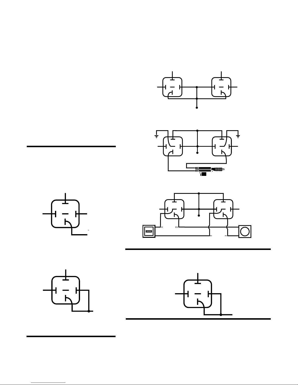
8. Mount the optional BRS-003 Relay Socket and SPDT Relay in a location where it is hidden from poten-
tial thieves. Find the vehicle’s STARTER wire and cut it in half. Connect the colored wires of the Relay Socket as fol-
lows:
BLACK = To STARTER wires on Starter side.
YELLOW = To STARTER wires on Switch side.
GRAY = ORANGE wire of the main harness.
9. Mount and connect any optional function modules included in the installation, following the mounting and
wiring directions supplied with them.

87
858687a
30
87
858687a
30
87
858687a
30
87
858687a
30
87
858687a
30
X CUT X
X CUT X
87
858687a
30
87
858687a
30
POWER DOOR LOCK
DIAGRAMS:
The BW-1600 comes equipped to
handle ground door lock installations.
The Blue and Green wires from the
Receiver Module are ready to tap
into grounding door lock systems.
The following door lock diagrams
require two SPDT Relays or the
appropriate accessories not included
with the BW-1600.These items must
be ordered separately.
POSITIVE TRIGGER DOOR LOCK CIRCUIT*:
TO DOOR LOCK RELAY
12 V FUSED CONSTANT
LOCK UNLOCK
TO DOOR UNLOCK RELAY
YELLOW WIRE
FROM ALARM
GRN/BK WIRE
FROM ALARM
12 V FUSED
CONSTANT
LOCK UNLOCK
If the power trunk
re-lease requires a
positive pulse to
operate, use this
circuit.
2nd CHANNEL
AUXILIARY
(BROWN WIRE)
12V POSITIVE
OUT TO TRUNK 12V
REVERSE POLARITY (DIRECTLY TO AD-ON ACTUATORS)✝:
GROUND GROUND
REVERSE POLARITY USING FACTORY SYSTEMS
✝
:
TRUNK RELEASE CIRCUIT DIAGRAM:
SWITCH ACTUATOR
LOCK
UNLOCK
✝For these reverse polarity applications, use the relay circuits shown
above or you can also use a 5-wire relay & socket kit (BRS-008P).
GRN/BK WIRE
FROM ALARM YELLOW WIRE
FROM ALARM
YELLOW WIRE
FROM ALARM
GRN/BK WIRE
FROM ALARM
12 V FUSED CONSTANT
87
858687a
30
WHITE/
YELLOW 12V
CONTANT
DOME LIGHT
DOME LIGHT RELAY
87
858687a
30
WHITE/
YELLOW
12V
CONTANT
DOME LIGHT
GROUND
(-) Dome Lights
(+) Dome Lights

CONNECTOR PIN NUMBERS AND WIRE COLOR CODES
10-PIN HARNESS
# WIRE COLOR FUNCTION NOTES
1) White Ignition Connect to a source of TRUE IGNITION, a wire that is
hot in both the RUN and START positions.
2) Red +12 VDC Main Power. Connect this wire to the POSITIVE
terminal of the vehicle’s battery, with the supplied
fuse installed at the BATTERY END of this wire.
3) Brown Starter Negative output to the Starter Interrupt relay.
Interrupt (–) See Wiring diagram for connections.
4) Black Ground Connect this wire to a clean, solid GROUND. Do Not
confuse this wire with the short, black antenna wire.
Do Not Ground The Antenna Wire!
5) Orange Channel 2 Negative output when Button #2 of the transmitter is
pressed for 3 seconds. See the diagram on Page 5.
2-PIN VALET/OVERRIDE PLUG-IN CONNECTORS:
# PLUG COLOR FUNCTION
1) Blue Valet Override Plug-in the Blue 2- pin connector for theVALET switch
Switch to the Blue receptacle on the circuit board.
2-PIN LED PLUG-IN CONNECTORS:
# PLUG COLOR FUNCTION
1) Red LED Plug-in the Red 2- pin connector for the LED
to the Red receptacle on the circuit board.
3-PIN DOOR LOCK PLUG-IN CONNECTOR:
# WIRE COLORS FUNCTION
1) Green Door Negative output pulse to door LOCK circuit. See
Lock (–) door lock wiring diagrams on Page 5 for connections.
2) Red (+) Optional 12 V Output.
3) Blue Door Negative output pulse to door UNLOCK circuit.
Unlock (–) See door lock wiring diagrams on Page 5 for connections.
2-PIN ACCESSORIES PLUG-IN CONNECTOR :
# FUNCTION
1) Red 3rd Channel See diasgram on page 5.
2) White/Yellow Dome light output See diasgram on page 5.
INSTALLATION MANUAL
BW-650 KEYLESS ENTRY
Please read this Black Widow manual carefully before attempting to install this system.
•BLACK WIDOW •
INSTALLATION MANUAL

(+)12V AT
BATTERY
ANTENNA (DO NOT GROUND THIS WIRE)
WHITE
RED
BROWN
TO BATTERY
FUSE
BLUE VALET
CONNECTOR
RED LED
CONNECTOR
JUMPER 1
JUMPER 2
DOOR LOCK
CONNECTOR
GREEN
RED
BLUE
BLACK
IGNITION
SWITCH
IGNITION
WIRE
LED
VALET SWITCH
CUT
XD1A
DIODE
OPTIONAL (+) 12V OUTPUT
30 87
87A
86
86
NEGATIVE DOOR
LOCK OUTPUT (SEE PAGE 5)
NEGATIVE DOOR
UNLOCK OUTPUT (SEE PAGE 5)
RECEIVER
MODULE HARNESS
OPTIONAL STARTER
INTERRUPT RELAY
3rd CHANNEL
DOMELIGHT
TO
STARTER
WHITE
RED/BLACK
ORANGE
2nd CHANNEL
BLACK GROUND
}
NOT USED
BY THIS
MODULE
JUMPER SETTINGS:
Jumper #1) OFF = 3 Second pulse.
Jumper #1) OFF = No auto lock with ignition
Ignition +12V MUST NOT DROP OUT during starting of vehicle.
WIRING DIAGRAM

PROBABLE SUGGESTED
SYMPTOM CAUSE CORRECTION
Alarm will not go RED or YELLOW wire not connected RED wire should connect directly to
into Code Learning to the correct power source. Code the battery. Connect YELLOW wire to
Mode Learning sequence done to slow. true ignition wire (Not at Fuse Block).
Redo Code Learning sequence faster.
Unit is triggered any BW296P sensor not adjusted correctly, Readjust BW-296P sensor.
time it is armed. BLUE or GREEN wire shorted Disconnect the BLUE or GREEN
to ground. wire to see if symptom stops if so
check wires for short.
Alarm will not rearm VIOLET wire is connected to pos- Check VIOLET and GREEN
or will not passively itive voltage, GREEN wire is wires with doors closed and
arm. connected to ground,YELLOW wire open, and YELLOW wire with
is connected to permanent positive ignition switch off and on, for
voltage, or pinswitch is bad. correct voltage changes. Repair
and/or rewire as needed.
Alarm will arm from Dipswitch #4 is off. Set dipswitch #4 to ON.
transmitter but will
not passively arm.
Remote Control does Defective Remote Control. Bad Replace Remote Control or its
not arm or disarm battery. Antenna wire is battery. Un-ground antenna.
alarm. grounded.
Valet does not work. Bad switch or wrong activation Repair or replace switch or check
sequence when using the transmitter user instructions for proper
activation sequence
Flashing output does Bad connection on WHITE Check WHITE wire. Connect
not work. wire or the drive polarity is a SPDT Relay to this wire and
wrong for the circuit being apply the opposite polarity to the
driven. circuit being driven.
Door locks do not Defective GREEN or BLUE Check GREEN and BLUE wires
lock/unlock correctly, wire from door lock connector plug, on door lock connector plug.
or action is reversed. GREEN and BLUE wires on door lock Check vehicle’s door lock
connector plug reversed, or wrong system for method of operation.
door lock wiring diagram used. Reverse wiring to door relays.

LIMITED LIFETIME WARRANTY
The Black Widow Division of DLC, Inc. warrants to the original purchaser that the
vehicle alarm system purchased will be free from defects in workmanship.
If it is determined that a defect exists, at our option, we will repair defective parts
or replace the system. If product is defective within one (1) year from date of pur-
chase, item will be repaired or replaced at no cost to original purchaser. If product is
defective after one (1) year from date of purchase, ship defective unit prepaid to
Black Widow Division, DLC, Inc. along with $20.00 U.S. ($30.00 Canadian) cashier’s
check or money order to cover cost of handling.
Proof of purchase by the original owner must accompany
warranty request before service is rendered.
This warranty covers normal use. It does not cover damage from alteration, misuse,
abuse, accident, improper installation or maintenance.Warranty does not cover
transmitter batteries or cases.This warranty gives you specific legal rights and you
may have rights which vary from state to state. If you have any questions,
contact your authorized Black Widow dealer.
DLC/U.S.A.
12753 Moore Street
Cerritos, California 90703
Table of contents
Other Black Widow Security Security System manuals

Black Widow Security
Black Widow Security BW FM 100 User manual

Black Widow Security
Black Widow Security BW RAS 130 User manual

Black Widow Security
Black Widow Security BW 690 User manual

Black Widow Security
Black Widow Security BW 700 User manual

Black Widow Security
Black Widow Security BW 690-C User manual

Black Widow Security
Black Widow Security BW 752 User manual

Black Widow Security
Black Widow Security BW FM 6150 User manual

Black Widow Security
Black Widow Security BW 690 User manual

Black Widow Security
Black Widow Security BW RAS 120 User manual