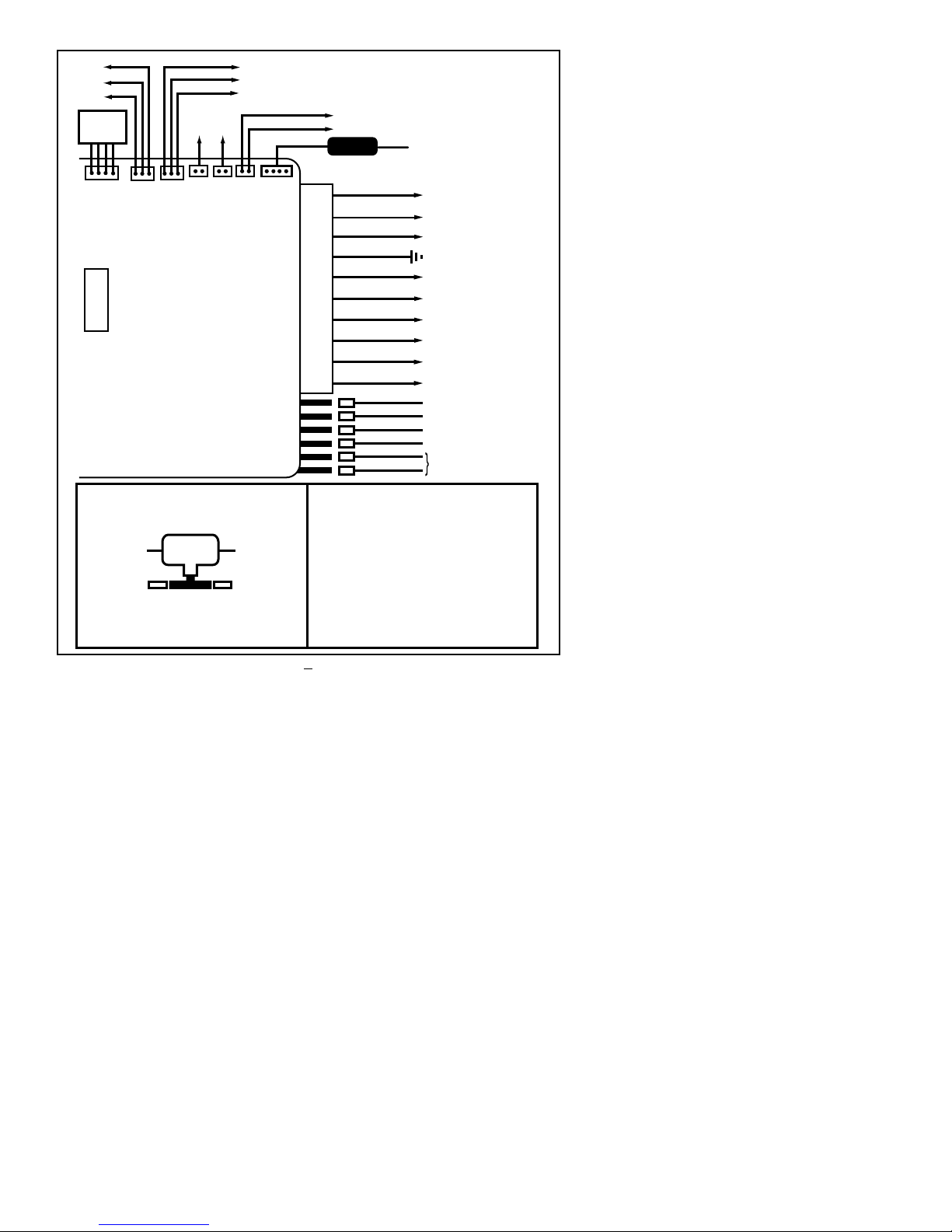
Black Widow Security BW RAS 130 User manual

INSTALLATION MANUAL
BEFORE INSTALLING THIS PRODUCT PLEASE READ
THIS INSTALLATION MANUAL THOROUGHLY!!
SECURITY SYSTEM W/ BUILT-IN
REMOTE AUTO START
This system is intended for installation on vehi-
cles equipped with automatic transmissions and
electronic fuel injection only!
DO NOT INSTALL THIS UNIT INTO A MANU-
AL TRANSMISSION VEHICLE AS IT COULD
RESULT IN SERIOUS INJURY OR DEATH.
• This product must be installed by qualified
personnel according to these instructions and
and observing all safety features.
• The system should be placed into the valet
mode when parked inside a garage or being left
for service.
• Always notify service personnel that the
vehicle is equipped with a Remote Starter.
• Only start the vehicle in a well ventilated
area. Do not use in a closed garage or indoors.
SYSTEM CONTENTS:
•Main unit
•4-button remote transmitter(s)*
•Plug In LED
•Plug in program switch
•Harness kit with 2 heavy duty fuse holders
•Hood Pin switch
•Extended range transceiver module
•Dual Stage Electronic Shock sensor
•120dB 6-tone siren
•Owner’s manual
*S-models provided with single transmitter
OPTIONAL ACCESSORIES:
•VAC-10 Vacuum Switch Kit
•APP-1 Universal OEM transponder bypass kit
•APV-1 GM VATS, Passlock I&II bypass kit
•PDLM-3 Power door lock relay module
1

2
Before you begin the installation:
•Verify that the vehicle is equipped with
electronic fuel injection.
•Verify that the vehicle is equipped with an
automatic transmission.
•Check to see if the vehicle is equipped with
any type of factory security system.
•Check to see if there is a pin switch for the
hood, if not one must be installed.
•Verify that the vehicle starts and idles prop-
erly before you start the installation.
•Verify with the customer the desired location
for the program switch and LED.
•Always use a multi-meter when verifying
vehicle wiring.
Remote Start Installation Notes:
The system senses the vehicle’s successful start
using one of the following methods:
1. Current sense
2. Tachometer sense
3. Spark or Coil Wire sense
4. Using optional vacuum switch.
If the Current Sense feature does not allow
proper operation, the tachometer sense/spark
sense wire may be used, or an optional vacuum
switch can be installed.
To use the tach sense/spark sense wire, set dip
switch #4 to the off position. Connect the gray
wire directly to the vehicle’s tach wire or extend
it into the engine compartment and wrap it
several times around a spark plug or coil wire.
In situations were a tach wire is unavailable or
does not allow proper operation,an optional vac-
uum switch can be installed. The vacuum switch
is designed to be placed in line with one of the
vehicle’s vacuum hoses and provide a ground out-
put (N/C) until the engine is started. To use the
vacuum switch, set dip switch #2 to the off posi-
tion. Connect the yellow wire (3-pin red con-
nector) to one terminal of the vacuum switch
and connect the other terminal to ground.
High-Current Wire Connections:
•RED WIRE #1 -Main power input; using the
supplied inline fuse holder, connect directly to
the vehicle’s battery or alternate power source
with a minimum 30 Amp supply.
•RED WIRE #2 - Secondary power input; using
the supplied inline fuse holder, connect directly
to the vehicle’s battery or alternate power
source with a minimum 30 Amp supply.
Note: If not connecting directly to the vehicle’s
battery, it is recommended to use separate
power sources (minimum 30Amp each) for each
red power wire.
•BROWN WIRE - Second ignition output;
connect to the wire that switches +12V and
does not drop out during cranking.
•YELLOW WIRE - Main ignition output;
connect to the main ignition wire that switches
+12 V and does not drop out during cranking.
•ORANGE WIRE - Main accessory output;
This provides +12V output to heater and/or air
conditioning system. Some cars may have more
than one accessory wire. In these vehicles add a
relay(s) to power the extra accessory wire(s).
•PURPLE WIRE - Starter output; connect to
the vehicle’s starter wire.

3
Main Harness:
•WHITE WIRE - Parking light output (+).
Connect to the wire that switches to +12V
when the parking lights are turned on. If the
vehicle’s parking light circuit exceeds 10 amps a
relay is required. For vehicle’s with independent
left and right parking light circuits, the parking
light wires must be connected using diodes to
keep the circuits separate.
•RED WIRE - +12V battery input.
•BROWN WIRE - Siren wire output (+).
Connect to the siren’s red wire. Connect the
siren’s black wire to ground.
•BLACK WIRE - Ground input (-). Connect to
a solid chassis ground that is clean and free of
paint or dirt.
•ORANGE WIRE - Armed Output and
Ground When Running Output (-). Connect to
a relay for starter defeat and starter anti-grind
protection. (See installation diagrams). The
ORANGE wire functions as a dual-purpose wire.
It provides a ground when the unit is armed to
activate a starter disable relay (using a starter
disable relay also provides starter anti-grind pro-
tection). It also provides a ground when the
remote start is engaged to activate an optional
factory security bypass module. When the Stop-
and-Go mode is engaged, the output will turn on
and remain active even after pressing the brake
pedal. Although the remote start shuts down
when the brake pedal is pressed, the output will
remain on until the ignition key is turned off.
•GRAY WIRE - Tach/Spark sense wire. If the
current sensing feature does not allow desired
operation, connect the GRAY wire directly to
the vehicle’s tach wire or negative fuel injector
wire, and set dip switch #4 to OFF. If the tach
wire is not accessible, wrap the GRAY wire
around a spark plug wire or coil wire several
times and secure with electrical tape.
•GREEN WIRE - Negative door trigger (-).
Connect to the door switch circuit wire that
shows ground when the door is open.
•BLUE WIRE - Hood switch input wire (-).
Connect this wire to the hood pin switch, this
will prevent the vehicle from remote starting if
the hood is opened. This is a safety input and
must be connected on all installations.
•VIOLET WIRE - Positive door trigger (+).
Connect to the door switch circuit wire that
shows +12V when the door is open. This type
of door circuit is usually found on Ford vehicles.
•YELLOW WIRE - Brake switch input wire,
connect this wire to the brake switch wire that
provides +12V when the brake pedal is pressed.
This is a safety input and must be connected
on all installations.
Plug in Connectors:
4-Pin White Connector: Plug-in connector
port for dual stage shock sensor.
3-Pin White Door Lock Connector: Plug-in
connector port for door lock harness or
optional door lock relay module (PDLM-3).
•BLUE WIRE - negative unlock output (-).
•REDWIRE - constant +12V low current out-
put (+) for relay modules, or inverters. 100mA
relay trigger only. Do NOTuse as a power
source for door lock relays.
•GREEN WIRE - negative lock output (-).

4
3-Pin Red Connector: Plug-in connector port
for optional features harness.
•GREEN/BLACKWIRE - 3rd channel output (-).
Connect to a relay for optional trunk release etc.
•RED WIRE - Factory Disarm output (-).
Connect to the wire that requires a ground
pulse to disarm the factory alarm system. The
RED wire provides a ground pulse when the
remote transmitter is used to unlock the doors
or start the vehicle.
•YELLOW WIRE - Vacuum Switch input. For
diesel vehicles, or vehicles where a tach wire or
spark plug wire is not available, the YELLOW
wire may be connected to an optional vacuum
switch. Connect the other side of the vacuum
switch to ground.
2-Pin Red Connector: Plug-in connector port
for LED. Mount LED in an area where it may be
easily seen from either side of the vehicle.
2-Pin Blue Connector: Plug-in connector port
for program/service switch. Mount program
switch in an area that is easily accessible from the
driver’s position.
2-PinWhite Connector: Plug-in connector port
for horn honk/dome light harness.
•WHITE/YELLOW - horn output (-)
•RED/BLACK - Dome light output (-)
5-Pin Antenna Connector: Plug-in connector
port for extended range receiver. Plug harness
into 5-pin connector, route cable up pillar post,
place double sided tape on flat side of receiver
module and place in corner of windshield.
Remote Programmable Features:
Step Function Button 1 (On) Button 2 (Off)
1. Arming Mode Passive Active
2. Passive Lock On Off
3. Auto Re-arm On Off
4. Normal/Silent Arming Normal Silent
5. Door Unlock Pulse Single Double
6. Door Lock Pulse Length .75 Seconds 3 Seconds
7. Ignition Lock On Off
8. Auto Cold Start Defeat Disable Cold Start Enable Cold Start
9. Cold Start Timing Every 2 Hours Every 1 Hour
10. Trunk Disarm Feature Disable Enable
11. Passive Arm Warning Chirps Delete On Off
12. Open Zone Chirp Timing 10 Seconds 60 Seconds
13. Remote Start Run Time 15 Minutes 25 Minutes
14. Lock Before & After Engine Crank On Off
15. Lock After Engine Shutdown On Off
16. Parking Light Operation Normal Car Locator Feature

5
Remote Programmable Features
To enter program mode:
1. Turn ignition to the on position.
2. Wait 2 seconds.
3. Within 10 seconds press program switch 5
times.
4. The siren will give one long chirp indicating
the system is now in program mode.
To change programmable features:
Press program switch the number of times that
equal to the feature you wish to change. The
siren will chirp each time the switch is pushed.
(Example: to turn feature #3 off press the
program switch 3 times).
•Press button 1 on the remote to turn the
feature on, the siren will chirp once.
•Press button 2 on the remote to turn
feature off- siren will chirp twice.
System will automatically exit program mode.
NOTE: You must re-enter program mode for
each feature you wish to change.
Programmable Features
Program #1: Arming Mode
On = Passive
Off = Active
Program #2: Passive Lock
On = Passive w/lock
Off = Passive no lock
Program #3: Auto Re-arm
On = Auto Re-arm enabled
Off = Auto Re-arm disabled
Program #4: Normal/Silent Arming
On = Normal operation
Off = Silent operation
Program #5: Door Unlock Pulse
On = Single
Off = Double
Program #6: Door Lock Pulse Length
On = 0.7 second door lock/unlock pulse
Off = 3 second door lock/unlock pulse
Program #7: Ignition Lock
On = Ignition auto lock
Off = No ignition auto lock
Program #8: Auto Cold Start Defeat
On = Disable Auto Cold Capability
Off = Enable Auto Cold Capability
Program #9: Cold Start Timing
On = Cold start every 2 hours
Off = Cold start every 1 hour
Program #10: Trunk Disarm Feature
On = Disabled
Off = Enabled
Program #11: Passive Arm Warning Chirps Delete
On = Passive arming without warning chirps
Off = Passive arming with warning chirps
Program #12: Open Zone Chirp Timing
On = Standard - 10 seconds
Off = Delayed - 60 seconds
Program #13: Remote Start Run Time
On = 15 minutes
Off = 25 minutes
Program #14: Lock Before & After Engine Crank
On = Lock when remote start activates
Off = Disabled
Program #15: Door Lock After Shut Down
On = Lock when remote start shuts down
Off = Disabled
Program #16: Parking Light Operation
On = Normal
Off = Car finder feature

6
Default Reset
To reset all programmable features to their fac-
tory default settings:
1. Turn ignition to the on position.
2. Wait 2 seconds.
3. Within 10 seconds press program switch 5
times. The siren will give one long chirp
indicating the system is now in program
mode.
4. Press transmitter button 3. The siren will
chirp 3 times and all programmable fea-
tures will be reset to the On position.
Dip Switch Settings
Make sure to set all dip switches in proper
position prior to mounting the module.
Dip Switch #1: Diesel Mode
On = Standard mode
Off = Diesel mode - Ignition turns on for 12-
13 seconds prior to cranking the starter
(to allow glow plugs to warm up).
Dip Switch #2: Vacuum switch
On = Current sense or tach/spark sense
Off = Vacuum switch sense
Dip Switch #3: Starter cranking time
On = Standard crank time
Off = Extended crank time (auto adjusts)
Dip Switch #4: Tach/Spark sense
On = Current sense
Off = Tach/Spark sense
Valet Mode
When the Valet mode is activated, the vehicle
will not start using the remote, but keyless
entry functions will still operate.
To enter valet mode:
1. Turn ignition to the on position.
2. Within 5 seconds, press and hold pro-
gram switch for approximately 2 seconds.
•The LED will light solid
•Parking lights will flash once
•The siren will chirp once
To exit valet mode:
1. Turn ignition to the on position.
2. Within 5 seconds press and hold program
switch for approximately 2 seconds.
•The LED will turn off
Adding or Deleting Remote Controls
When you enter the code learning mode, the
system will learn new remotes and automatically
delete all other remotes that were previously
operating the system.
NOTE: You must code all desired remotes at
this time. The system can learn a maximum of
three transmitters.
To enter Code Learning Mode:
1. Turn ignition key on, off, on, off, and leave
on within 5 seconds.
LED will flicker and parking lights will flash
once.
2. Press and hold program switch for 2 sec-
onds.
3. LED will flicker and parking lights will flash.
The siren will give a series of chirps (as
long as arming chirps are on).
4. Release the program switch.
5. Program all desired remotes by pressing
button #1 on each of the transmitters.
The siren will chirp after the system has
learned each remote control (as long as
arming chirps are on).
6. Turn ignition key off.
Remotes are now programmed to the
system.
Bypassing Factory Theft Deterrent

7
Bypassing Factory Theft Deterrent
Systems
Many newer vehicles are now factory-equipped
with anti-theft systems that use either a resistor
coded key or a passive transponder that dis-
ables the fuel system unless a properly coded
key is inserted into the ignition cylinder. To inte-
grate a remote starter into these vehicles, you
must determine which type of factory anti-
theft system is equipped, then use the proper
bypass module for that system.
General Motors Anti-theft Systems:
Many late-model GM vehicles are equipped with
one of three basic anti-theft systems; Passkey,
Passlock, and Passkey 3. Standard Passkey sys-
tems are easily identified by the resistor chip
visible on the shaft of the key. Passlock systems
do not rely on a resistor equipped key. Instead
they use a resistance code generated when the
key is turned in the ignition cylinder. Both of
these systems have an anti-theft indicator in the
instrument cluster. To properly interface into
these systems and retain full functionality of the
factory anti-theft system,use the APV-1 module.
The Passkey 3 system, which is found on GM
vehicles 1999 and newer, is a transponder based
system (described below). Use the APP-1
module to integrate into Passkey 3 equipped
vehicles. This module allows full functionality of
the factory anti-theft system and requires the
use of a spare key.
Passive Transponder Systems:
Passive transponder systems have become the
most popular anti-theft system among vehicle
manufacturers (Ford, Honda, BMW, Toyota,
Nissan and others). This system requires use of
a tiny passive transmitter housed in the base of
the key.This device activates when placed close
to the vehicle’s ignition switch. The starter will
usually crank but the fuel system will be dis-
abled, mot allowing the vehicle to run, if the
transponder is not detected.To properly inter-
face into transponder systems, use the APP-1
module. This module allows full functionality of
the factory anti-theft system and requires the
use of a spare key.

8
FIGURE 1. OPTIONAL VACUUM
SWITCH INSTALLATION
VACUUM
SWITCH
EXISTING CAR
VACUUM HOSE
YELLOW WIRE
(VACUUM SWITCH
INPUT ON MAIN UNIT
GROUND
EXISTING CAR
VACUUM HOSE
For optional vacuum switch installation: dip switch #2=OFF
COLD START ACTIVATION
Automatically starts engine every 1 or 2 hrs. for 24 hrs. max.
While pressing brake pedal, push program switch then
press transmitter button 4. The parking lights will flash
5 times and remain on. Engine will start and run for 30
seconds to confirm activation, then shut down. Once
activated the engine will start automatically and run
for the preset run time.
COLD START DEACTIVATION
The Cold Start feature can be deactivated by stepping
on the brake pedal, or remote starting the vehicle using
the transmitter.
WIRING HARNESS
RED
YELLOW IGNITION #1 OUTPUT
BROWN IGNITION #2 OUTPUT
RED CONNECT EACH DIRECTLY
TO THE BATTERY (See page 2 )
GREEN DOOR TRIGGER (-)
VIOLET DOOR TRIGGER (+)
BLACK GROUND INPUT
ORANGE ARMED OUTPUT/
GROUND WHEN RUNNING (-)
WHITE
PARKING LIGHT OUTPUT (+)
RED +12V INPUT
HOOD SWITCH INPUT(-)
BLUE
BROWN SIREN OUTPUT(+)
GRAY TACH/SPARK SENSE (-)
VIOLET STARTER OUTPUT
ORANGE ACCESSORY OUTPUT
YELLOW BRAKE SWITCH INPUT (+)
BLUE
GREEN
RED
UNLOCK(-)
+12V
LOCK(-)
#1
#2
#3
#4
DIP SWITCH SETTINGS
Default settings from
factory are ON
1. ON = Normal operation
OFF = Diesel mode - ignition will turn ON
several seconds before starting vehicle.
2. ON = Normal operation
OFF = Vacuum switch mode - reads YELLOW wire
(3-pin accessory plug) for optional vacuum switch
3. ON = Normal operation
OFF = Extend cranking time - automatically adjusted
4. ON = Dip switch #2 selection (normal/vacuum)
OFF = Tach/Spark sense - reads GRAY tach/spark
sense wire.
CONNECTORS #5
#6
VACUUM SWITCH INPUT
FACTORY DISARM OUTPUT (-)
TRUNK OUTPUT (-)
1 2 3 4
GREEN/BLACK
YELLOW
RED
WHITE/YELLOW
RED/BLACK HORN OUT(-)
DOME LIGHT (-)
LED
SWITCH
RF RECEIVER
SHOCK
SENSOR
PLUG
SECURITY/REMOTE START WIRING DIAGRAM

9
Problem
Unit will not operate.
Keyless Entry features operate
but vehicle will not start.
Vehicle will not remote start.
Engine cranks but not long
enough to allow vehicle to start.
System will not go into Code
Learning or Programming Mode.
Car horn honks and vehicle will
not start.
Vehicle starts without pressing
Remote Transmitter.
Vehicle cranks and begins to run,
then shuts off.
Vehicle cranks and begins to run,
then shuts off.
Probable Cause
All power inputs are not con-
nected to +12V.
System in Service Mode LED is
on solid.
Safety inputs are triggered.
Crank time must be increased.
Ignition #1 (Yellow Wire ) is on
wrong connector - Ignition #2
Vehicle has a factory alarm sys-
tem.
System in Automatic Cold Start
Activation Mode.
Voltage sense is not working.
Use either the spark sense or
tach sense.
Vehicle has a factory theft deter-
rent system that prevents start-
ing w/o key in ignition.
Suggested Correction
Main Inputs (heavy gauge red
wires) and small red wire on
main harness must be connected
to +12V.
Turn ignition key to on position,
press and hold service switch for
5 seconds.The LED will turn off.
Check Brake Switch Input (+)
(Yellow Wire) or Hood Input (-)
(Blue Wire).
Place dip switch #3 to the ON
position.
Connect the main ignition out-
put to the Ignition #1 connec-
tor on the main unit.
Connect red wire on accessory
plug (red plug) to Factory Alarm
Disarm wire.
To exit press brake pedal or turn
Ignition key on, or activate
remote start using the remote
transmitter.
Wrap the gray wire around a
spark plug wire or connect to
either the tach wire or a negative
fuel injector wire. Set dip switch
#4 in the OFF position.
See Bypassing Factory Theft
Deterrent Systems.
REMOTE START TROUBLESHOOTING

10
Problem
Alarm will not go into Code Learning
Mode.
Alarm will not rearm or will not pas-
sively arm.
Flashing light output does not work.
Door locks do not lock/unlock correct-
ly, or action is reversed
Probable Cause
RED or YELLOW wire not connected
to the correct power source. Code
Learning sequence performed too slow-
ly.
Door is open,VIOLET wire is connected
to positive voltage, GREEN wire is con-
nected to ground, main YELLOW wire
(ignition wire) is connected to +12V, or
door pin switch is bad.
Bad connection on WHITE wire or the
output polarity is wrong for the circuit
being driven.
Defective GREEN or BLUE wire from
door lock connector plug, GREEN and
BLUE wires reversed, or wrong door
lock wiring diagram used.
Suggested Correction
RED wire should connect directly to
the battery. Connect YELLOW wire to
true ignition wire (NOT AT FUSE
BLOCK). Perform Code Learning
sequence faster.
Check VIOLET and GREEN wires with
doors closed and open, and YELLOW
wire with ignition switch off and on for
voltage changes.Repair and/or rewire as
needed.
Check WHITE wire. Connect a SPDT
relay to this wire and apply the opposite
polarity to the circuit being driven.
Check GREEN and BLUE wires on door
lock connector plug, Check vehicle’s
door lock system for method of opera-
tion. Reverse wiring to door relays.
SECURITY SYSTEM TROUBLESHOOTING
STATUS INDICATOR (LED) FUNCTIONS
On Solid = Valet Mode
Slow Flash = System Armed
Rapid Flash = Passive Arming
Flash 2x = Remote Start
Flash 3x = Stop and Go Mode
Flash 4x = Cold Start Mode
PARKING LIGHTS FUNCTIONS
On Solid = Vehicle Remote Starting
Flash 1x = Doors Locked
Flash 2x = Doors Unlocked
Flash 3x = Open Zone Indication (after arming)
Flash 4x = Remote Starting Failed
Flash 5x = Auto Cold Start Engaged

11
POSITIVE TRIGGER DOOR LOCK CIRCUIT:
REVERSE POLARITY (ADDING ACTUATORS):
REVERSE POLARITY USING FACTORY SYSTEMS:
GROUND
GREENWIRE
FROM ALARM
GROUND
BLUEWIRE
FROM ALARM
GREENWIRE
FROM ALARM BLUE WIRE
FROM ALARM
TO POSITIVE LOCKWIRE TO POSITIVE UNLOCKWIRE
UNLOCK RELAY
UNLOCK RELAY
LOCK RELAY
LOCK RELAY
UNLOCK RELAYLOCK RELAY
GREENWIRE
FROM ALARM BLUE WIRE
FROM ALARM
SWITCH
LOCK
UNLOCK
--X
CUT
X--
-XCUTX-
ACTUATOR
GROUND
WHITE/
YELLOW
TO NEGATIVE HORN HONK
WIRE
12V+ WHITE/
YELLOW
TO POSITIVE HORN HONK
WIRE
12V+
12V+
12V+
12V+
TO NEGATIVE DOME LIGHT
WIRE TO POSITIVE DOME LIGHT
WIRE
12V+
12V+
GROUND
RED/
BLACK RED/
BLACK
TOVEHICLE
PARKING LIGHT
CIRCUIT
FOR NEGATIVE
PARKING LIGHTS
(MOST JAPANESE VEHICLES)
TRUNK RELEASE
CIRCUIT DIAGRAM:
ADDED RELAY TO PREVENT
GRINDING STARTER AFTER
REMOTE AUTO START
TO TRUNK RELEASEWIRE
12V+
(GREEN/
BLACK
WIRE)
ORANGEWIRE
(MAIN HARNESS)
CUT
X
TO BATTERY
TO STARTER
MOTOR
IGNITION
SWITCH
PURPLE WIRE
(HEAVY GAUGE)
87
87a
86 30 85
87
87a
86 30 85
87
87a
86 30 85
87
87a
86 3085
87
87a
86 30 85
87
87a
86 30 85
87
87a
8630 85
87
87a
86 30 85
87
87a
86 30 85
87
87a
86 30 85
87
87a
86
30
85
87
87a
86 30 85
87
87a
86 30 85
HORN HONK DIAGRAM:
DOME LIGHT DIAGRAM:
GROUND
WHITEWIRE
FROM ALARM
12V+
IGNITION
POWER DOOR LOCK RELAY
DIAGRAMS:
This system provides negative door
lock outputs. Positive trigger or reverse
polarity installations require two SPDT
relays or the PDLM-3 Power Door
Lock Relay Module (not included).
Connect relays as shown in the illus-
trations provided.

12
© 2001, DLC, INC. 64-130, 10/01 Rev. 2
Other manuals for BW RAS 130
1
This manual suits for next models
2
Table of contents
Other Black Widow Security Security System manuals

Black Widow Security
Black Widow Security BW 690-C User manual

Black Widow Security
Black Widow Security BW 752 User manual

Black Widow Security
Black Widow Security BW-1600 User manual

Black Widow Security
Black Widow Security BW 700 User manual

Black Widow Security
Black Widow Security BW RAS 120 User manual

Black Widow Security
Black Widow Security BW FM 100 User manual

Black Widow Security
Black Widow Security BW 690 User manual

Black Widow Security
Black Widow Security BW 690 User manual

Black Widow Security
Black Widow Security BW FM 6150 User manual