Blackrock Microsystems NeuroPort User manual
630 Komas Drive | Suite 200
Salt Lake City | UT 84108 | USA
P +1 801.582.5533 | F +1 801.582.1509
www.blackrockmicro.com
Revision 5.00/ LB-0323 –NeuroPort Quick Guide –March 15th, 2018
© 2018 Blackrock Microsystems, LLC
NeuroPort™
Biopotential Signal
Processing System
Quick Guide

Revision 5.00/ LB-0323 –NeuroPort Quick Guide
© 2018 Blackrock Microsystems, LLC
2
Table of Contents
Table of Contents..........................................................................2
Symbols of Contraindications, Warnings, and Precautions ..........4
Intended Use and Indications for Use...........................................5
Contraindications ..........................................................................5
Warnings.......................................................................................5
Specifications................................................................................7
System Description .....................................................................10
System Schematic................................................................................ 10
System Components............................................................................ 10
Hardware Specifications .............................................................11
Hardware Overview.....................................................................12
Neural Signal Processor (NSP).......................................................... 12
Neural Signal Amplifier and Amplifier Power Supply (APS)............ 12
Cables and Connectors....................................................................... 13
Digital Neural Signal Simulator (DNSS)............................................. 14
Software Setup............................................................................15
Software Overview......................................................................16
Installation............................................................................................. 16
Central................................................................................................... 16
Hardware Configuration....................................................................... 16
Spike Panel........................................................................................... 17
Raster Plot ............................................................................................ 17
Single Neural Channel......................................................................... 18
File Storage........................................................................................... 18
Oscilloscope.......................................................................................... 19

Revision 5.00/ LB-0323 –NeuroPort Quick Guide
© 2018 Blackrock Microsystems, LLC
3
Digital Filter Editor................................................................................ 20
Activity Map........................................................................................... 21
Signal-to-Noise Ratio........................................................................... 21
Neural Modulation................................................................................ 22
Thresholding......................................................................................... 22
Impedance Tester ................................................................................ 23
Crosstalk................................................................................................ 23
N-Trode ................................................................................................. 24
nPlay Server ......................................................................................... 24
Cleaning and Maintenance .........................................................25
Return Merchandise Authorization..............................................25
Warranty......................................................................................25
Support........................................................................................26

Revision 5.00/ LB-0323 –NeuroPort Quick Guide
© 2018 Blackrock Microsystems, LLC
4
Symbols of Contraindications,
Warnings, and Precautions
IEC 60101-0102
Danger of
Electrostatic
Discharge
(ESD)
IEC 60417-5019
Protective earth
(ground)
IEC 60417-5036
Dangerous
voltage
IEC 60417-5021
Equipotentiality
Connector
IEC 60417-5333
Type of BF
Applied Part
|
IEC 60417-5007
ON (power)
IEC 60417-5008
OFF (power)
IEC 60417-5009
Stand-by
CSA 60950-1-03
UL 60950-1
Class 1 Laser
Product
f
ISO 7000-2496
Serial Number
M
ISO 7000-3082
Manufacturer
P
BS EN ISO
15223-1
EC Representative
Y
ISO 7000-0434A
Warning
i
ISO 7000-1641
Read the
documentation
g
ISO 7000-2492
Batch
BS EN ISO
15223-1
Sterilized using
ethylene oxide
h
ISO 7000-2493
Catalogue
Number

Revision 5.00/ LB-0323 –NeuroPort Quick Guide
© 2018 Blackrock Microsystems, LLC
5
Intended Use and Indications for Use
The Blackrock NeuroPort Biopotential Signal Processing System supports recording, processing and
displaying biopotential signals from user supplied electrodes. Biopotential signals include
Electrocorticography (ECoG), electroencephalography (EEG), electromyography (EMG),
electrocardiography (ECG), electrooculography (EOC) and evoked potentials (EP).
The NeuroPort Biopotential Signal Processing System is not a monitoring system. No physiological
alarms are provided. The acquisition and display of biopotential signals is for the interpretation and use of
the clinician.
Contraindications
•The NeuroPort System is a recording system and should not be used in applications involving
stimulation
Warnings
•A thorough understanding of the technical principles and risks associated with electrophysiological
recording is necessary before using this product.
•Only connect NeuroPort System components to properly tested, grounded and dedicated AC outlets
using only the Blackrock provided power cables to reduce the risk of electrical shock. Do not use an
adapter for ungrounded wall outlets.
•Read this entire manual prior to using the device.
•Completion of the Blackrock Microsystems user training program is required prior to the use of the
NeuroPort System.
•Do not connect the NeuroPort System to an outlet controlled by a wall switch, multiple socket-outlet
or extension cord to avoid fires or other electrical hazards.
•Do not use the NeuroPort System in the presence of flammable anesthetic agents.
•Avoid strong static discharges from sources like televisions or computer monitors because they can
damage the electrical parts of the system.
•Always operate the NeuroPort System in a clean environment.
•Keep the NeuroPort System away from liquids. Contact with water, shower spray, or wet surfaces can
lead to the patient receiving an electrical shock.
•Connection of external instruments may compromise electrical safety compliance with IEC 60601-1.
•The NeuroPort System should be disconnected from any electrodes during cardiac defibrillation.
•The conductive parts of electrodes and their connectors, including neural electrodes, should not
contact other conductive parts including earth or patient.
•Repair or maintenance is not allowed during equipment operation.
•Only plug in Blackrock approved equipment into the NeuroPort System.

Revision 5.00/ LB-0323 –NeuroPort Quick Guide
© 2018 Blackrock Microsystems, LLC
6
Precautions
•Follow the restrictions of use for third party electrodes or arrays.
•Third party recording systems connecting to the NeuroPort System and components must be
electrically isolated for patient safety.
•The NeuroPort System must be disposed of at an electronic waste facility that is permitted in
compliance with the Waste Electrical and Electronic Equipment Directive (WEEED)

Revision 5.00/ LB-0323 –NeuroPort Quick Guide
© 2018 Blackrock Microsystems, LLC
7
Specifications
Model Name
NeuroPort Biopotential Signal Processing
System
Power Requirements
110 VAC 60 Hz / 240 VAC 50 Hz, 8.0 Amps
maximum load
Serviceable Fuses
5 x 20 mm, 250 V, 1.6 A, Slow Blow
Compliance Standards
IEC 60601-1, IEC 60601-1-2, IEC 60601-2-26,
CSA listed
Type of Protection Against Electric Shock
Class 1
Degree of Protection
Type BF Applied Part (Amplifier)
Mode of Operation
Continuous
Water Ingress Protection
Ordinary Equipment, not fluid resistant, IPX0
Operating Environment
10˚C to 40˚C, 5% to 95% R.H. (non-
condensing)
Storage Environment
-20˚C to 50˚C, 5% to 100% R.H. (non-
condensing)
Revision 5.00/ LB-0323 –NeuroPort Quick Guide
© 2018 Blackrock Microsystems, LLC
8
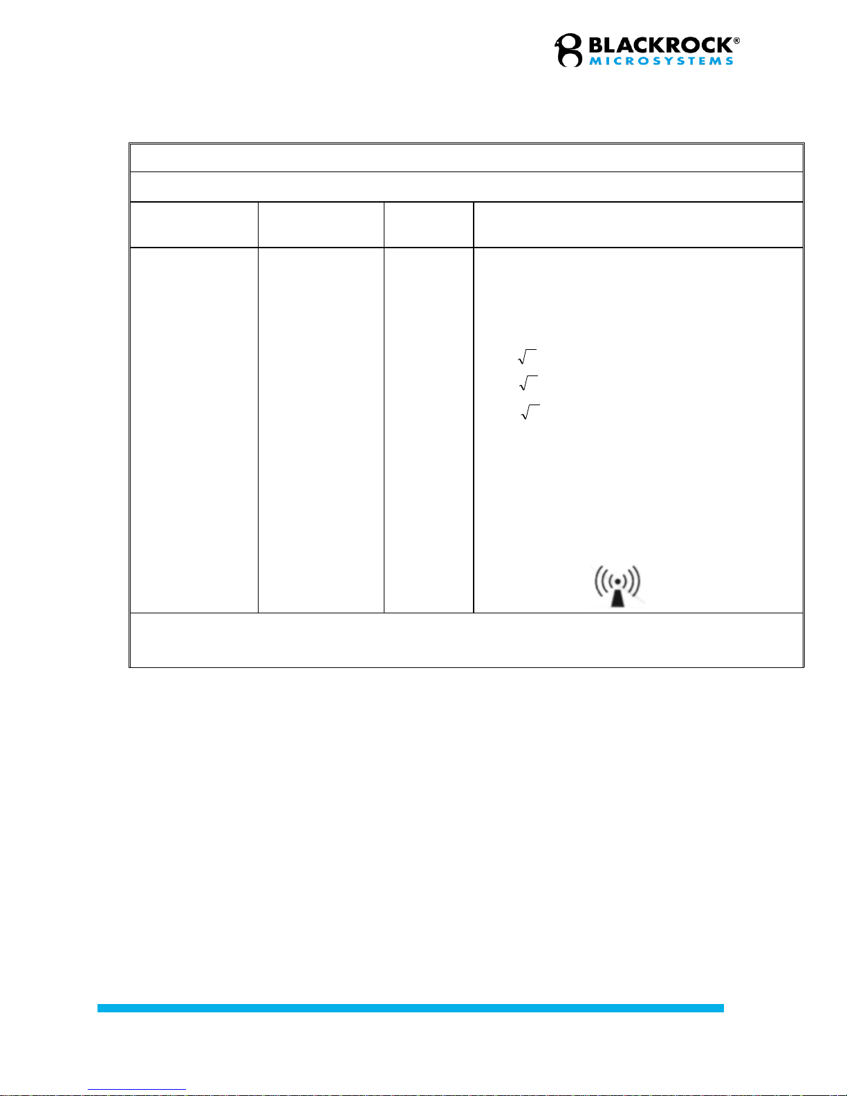
Guidance and manufacturer’s declaration – electromagnetic immunity –for all EQUIPMENT and SYSTEMS that
are not LIFE-SUPPORTING (refer to 60601-1-2).
Guidance and manufacturer’s declaration —electromagnetic immunity
The NeuroPort is intended for use in the electromagnetic environment specified below. The customer or the user of the NeuroPort
should assure that it is used in such an environment.
Immunity test
IEC 60601 test
level
Compliance
level
Electromagnetic environment —guidance
Portable and mobile RF communications equipment
should be used no closer to any part of the NeuroPort,
including cables, than the recommended separation
distance calculated from the equation applicable to the
frequency of the transmitter.
Recommended separation distance
150 kHz to 80 MHz
Conducted RF
IEC61000-4-6
3 V rms
150 kHz to 80 MHz
3 V
Pd 2.1
80 MHz to 800 MHz
Pd 3.2
80 MHz to 2.5 GHz
Radiated RF
IEC 61000-4-3
3 V/m
80 MHz to 2.5 GHz
3 V/m
where P is the maximum output power rating of the
transmitter in watts (W) according to the transmitter
manufacturer and d is the recommended separation
distance in meters (m).
Field strengths from fixed RF transmitters, as determined
by an electromagnetic site surveyshould be less than the
compliance level in each frequency range. Interference
may occur in the vicinity of equipment marked with the
following symbol:
NOTE 1: At 80 MHz and 800 MHz, the higher frequency range applies.
NOTE 2: These guidelines may not apply in all situations. Electromagnetic propagation is affected by absorption and
reflection from structures, objects and people.
Pd 2.1
Revision 5.00/ LB-0323 –NeuroPort Quick Guide
© 2018 Blackrock Microsystems, LLC
9
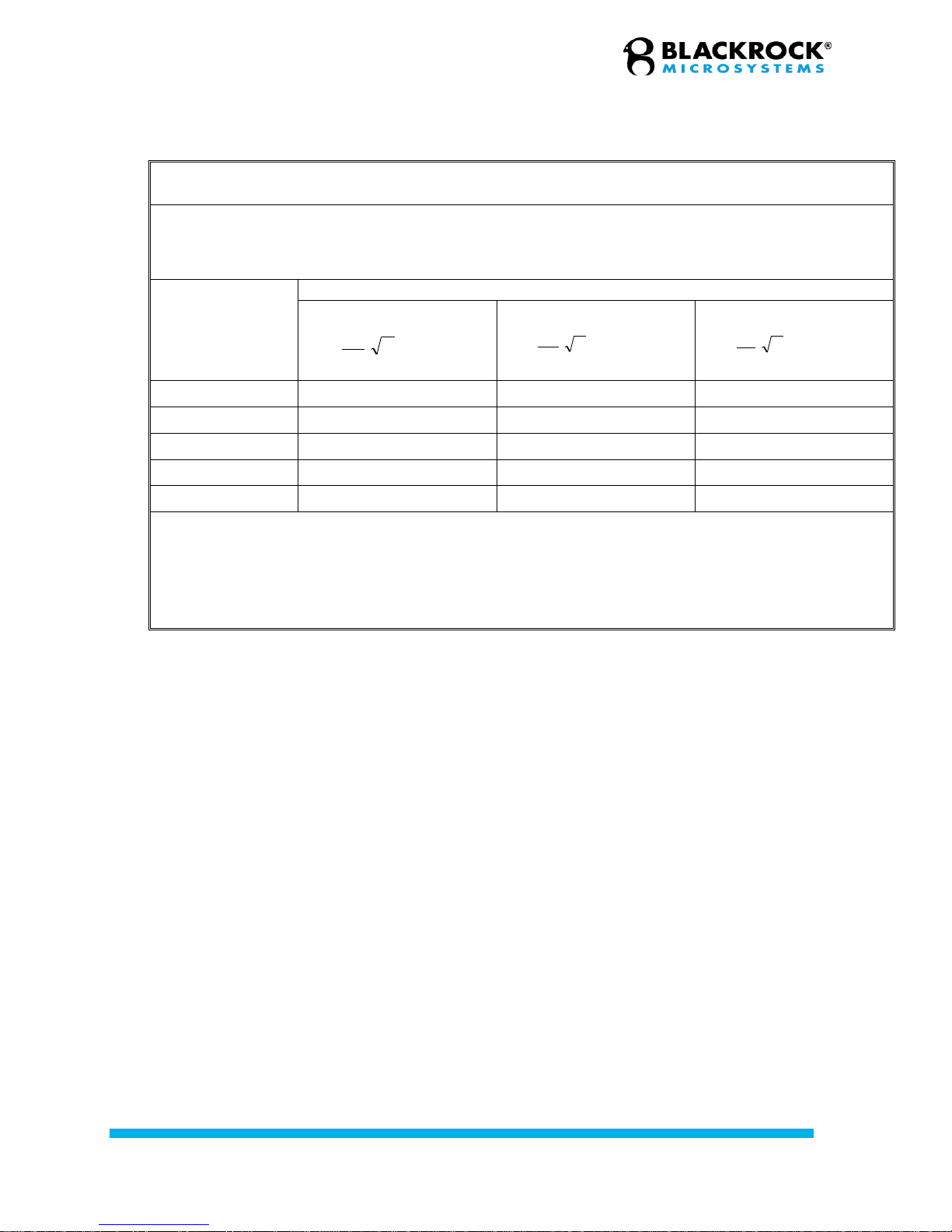
Recommended separation distances between portable and mobile RF communications equipment and the
EQUIPMENT or SYSTEM - for EQUIPMENT or SYSTEMS that are not LIFE-SUPPORTING (refer to 60601-1-2).
Recommended separation distances between portable and mobile RF communications equipment and the
NeuroPort
The NeuroPort is intended for use in an electromagnetic environment in which radiated RF disturbances are
controlled. The customer or the user of the NeuroPort can help prevent electromagnetic interference by maintaining a
minimum distance between portable and mobile RF communications equipment (transmitters) and the NeuroPort as
recommended below, according to the maximum output power of the communications equipment.
Rated maximum
output power of
transmitter W
Separation distance according to frequency of transmitter m
150 kHz to 80 MHz
P
V
d]
5.3
[
1
80 MHz to 800 MHz
P
E
d]
5.3
[
1
800 MHz to 2.5 GHz
P
E
d]
7
[
1
0.01
0.12
0.12
0.23
0.1
0.38
0.38
0.73
1
1.2
1.2
2.3
10
3.8
3.8
7.3
100
12
12
23
For transmitters rated at a maximum output power not listed above, the recommended separation distance d in
meters (m) can be estimated using the equation applicable to the frequency of the transmitter, where P is the
maximum output power rating of the transmitter in watts (W) according to the transmitter manufacturer.
NOTE 1: At 80 MHz and 800 MHz, the separation distance for the higher frequency range applies.
NOTE 2: These guidelines may not apply in all situations. Electromagnetic propagation is affected by absorption and
reflection from structures, objects and people.

Revision 5.00/ LB-0323 –NeuroPort Quick Guide
© 2018 Blackrock Microsystems, LLC
10
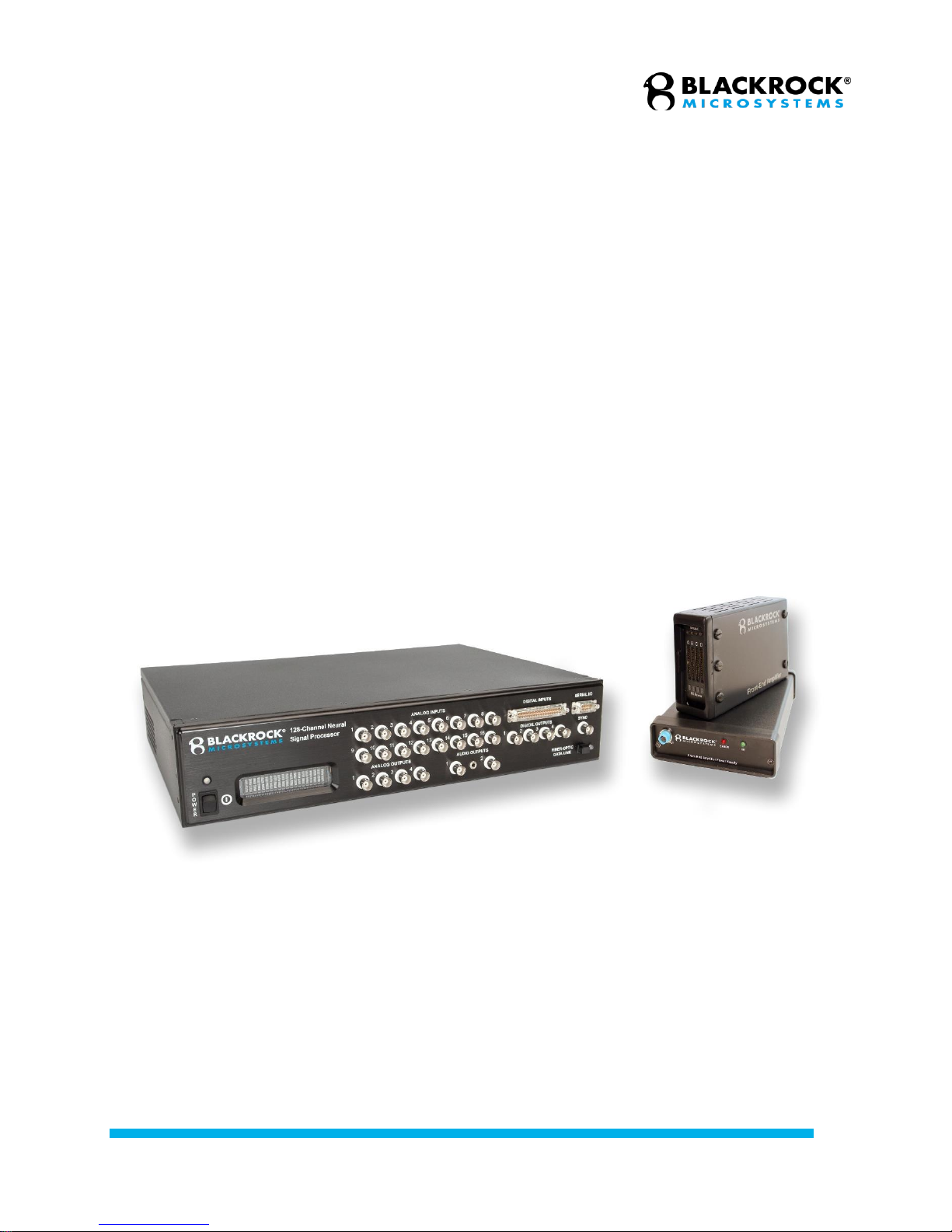
System Description
The NeuroPort System is designed to record and process neural signals from up to 256 surface or
penetrating electrodes in addition to analog and digital experimental events. The system is capable of
performing several online processing algorithms on neural signals, including noise cancellation,
adjustable digital filtering, simultaneous extraction of spike and field potentials, and automatic online spike
sorting.
System Schematic
System Components
•Neural Signal Processor
•Neural Signal Amplifier and Amplifier Power Supply (APS)
•Digital Neural Signal Simulator (DNSS) (optional)
•Power cables and connectors
•User’s Quick Guide and software CD

Revision 5.00/ LB-0323 –NeuroPort Quick Guide
© 2018 Blackrock Microsystems, LLC
11
Hardware Specifications
NEUROPORT NEURAL SIGNAL AMPLIFIER /DIGITIZER
NEUROPORT NEURAL SIGNAL PROCESSOR
Input Range
± 8.192 mV
Digital Signal
Processing
Adaptive Line Noise Cancellation and 4th-order hi/lo
pass digital filtering for all channels. Separate filters
for simultaneous continuous and spike streams
along with online spike classification using
time/amplitude and/or template matching.
Analog to Digital
Conversion
16-bit digital output, with 0.25
µV per bit resolution
Input Impedance
> 1012 ohms || 3pF
Input Bias/Leakage
+5pA typical, ±20pA max
Input Referred Noise
< 3.0µVrms (14µVp-p)
Neural Signal Inputs
Up to 256-Channels
Common Mode
Rejection Ratio
> 90 dB at 50/60 Hz
Neural Signal Input
Sample Rate
30,000 Samples/second
Common Mode Input
Range
up to ±3.0 V between inputs
and ground
Experimental Analog
Inputs
Sixteen ±5 V, 16-bit inputs for experiment or neural
signal processing
Differential Input
Range
up to ±3.0 V between
electrode and reference inputs
Experimental Digital
I/O
One 16-bit input port (DB-37) with Word and Packet
Strobe control lines.
One RS232 I/O port (DB-9) with
115k baud input and output.
Four single-bit digital outputs (BNC) with
programmable monitoring functions.
One TTL output (BNC) sampling synchronization
output port.
Maximum Input
Voltage Range
up to ±5.0 V between any
input and ground
Crosstalk between
channels
< 1 LSB for all configurations
Filter characteristics
1st order Butterworth (high),
3rd order Butterworth (low)
High Pass Cutoff
Freq
0.3 Hz (full-bandwidth mode)
Experiment Analog
Outputs
Four each ±5 V, 600 ohm, 16-bit outputs for
monitoring and stimulus waveforms
Low Pass Cutoff Freq
7.5 kHz
Audio Outputs
Two each 1 V line-level outputs
Headstage Power
Supply
±5.0 V output, up to 150 mA
for powering optional
headstages
Multi-NSP
Synchronization
From PC trigger to digital or serial input ports
Control/Data Output
Connection
MT-RJ fiber-optic port with 2-
way 150 Mbps 8B/10B
encoded data-stream and 32-
bit CRC data validation
PC Hardware Interface
1 Gigabit Ethernet
PC Software Interface
Windows 7 x64 or Windows 10 x64
External Power
Supply
Five-channel with monitoring,
sequencing, and emergency
shutdown control
Power Supply
Standard 3-pin PC power connector accepting 110-
240 VAC, 50-60 Hz
Input
120 or 240 VAC, 50-60Hz
Output
+5.0 V, 500 mA analog,
–5.0 V, 500 mA analog,
+3.3 V, 300 mA digital,
+3.3 V, 500 mA digital,
+5.0 V, 300 mA digital
Fused Input
0.7A Slow Blow Fuses
Revision 5.00/ LB-0323 –NeuroPort Quick Guide
© 2018 Blackrock Microsystems, LLC
12
Hardware Overview
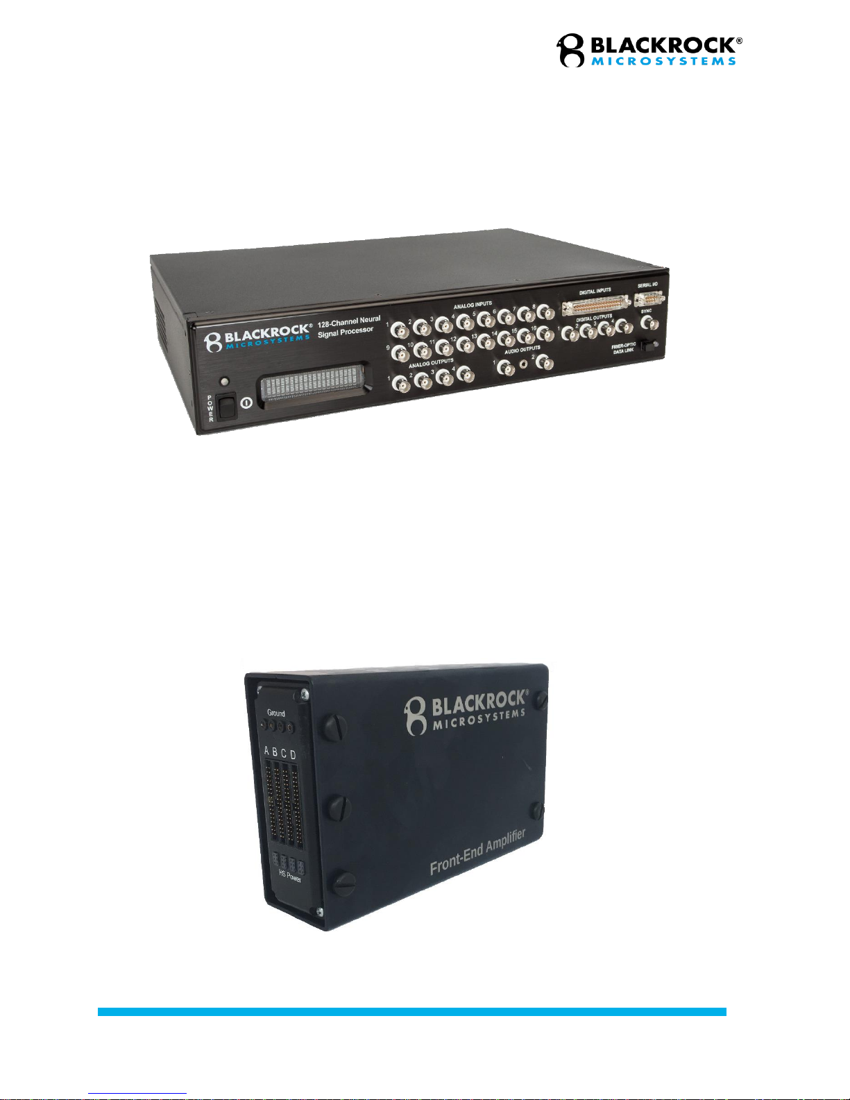
Neural Signal Processor (NSP)
The NSP performs processing and on-line analysis of the neural signals and then transmits this
data to the connected host PC via an Ethernet link. The NSP is comprised of a status LCD, 16
BNC analog input channels with an input range of ±5V (source impedance < 100Ω), a 16-bit DB-
37 digital input that is capable of reading data at 30 kHz, a DB-9 serial I/O port, 4 BNC analog
outputs, 2 audio outputs, 4 BNC digital outputs, a BNC sync output, a fiber-optic port to connect
to the Amplifier, and a NSP sync port on the back.
Neural Signal Amplifier and Amplifier Power
Supply (APS)
Figure 1—Neural Signal Processor
Figure 2—Amplifier
Revision 5.00/ LB-0323 –NeuroPort Quick Guide
© 2018 Blackrock Microsystems, LLC
13
The amplifier, Figure 2, receives signals directly from the electrodes through the headstage and
the patient cable. The sampled signal (up to 30 kHz) gets amplified, filtered (bandpassed at 0.3-
7,500 Hz) and digitized (16-bits at 250 nV resolution) and then is transmitted to the NSP via a
fiber optic link. The Amplifier ground is not directly connected to the ground pin of the AC
connector. There are ESD shunt circuits that will conduct differences of 1000 V or more. The
amplifier is isolated and floating.
The amplifier has four 34-pin banks. Each bank consists of 32 channels, a reference electrode
pin, and a ground. In addition, four 6-pins power supply banks provide power (±5V) to the
headstage and can deliver 130 mA of combined current to the amplifier. The ground pins on
every connector are internally connected to the grounding post on the back side of the unit.
The Amplifier Power Supply, Figure 3, consists of five analog and digital supply channels with
monitoring, sequencing and emergency shutdown control. In the event of an error in voltage or
power delivery, the power supply will shut down and the red error light will illuminate.
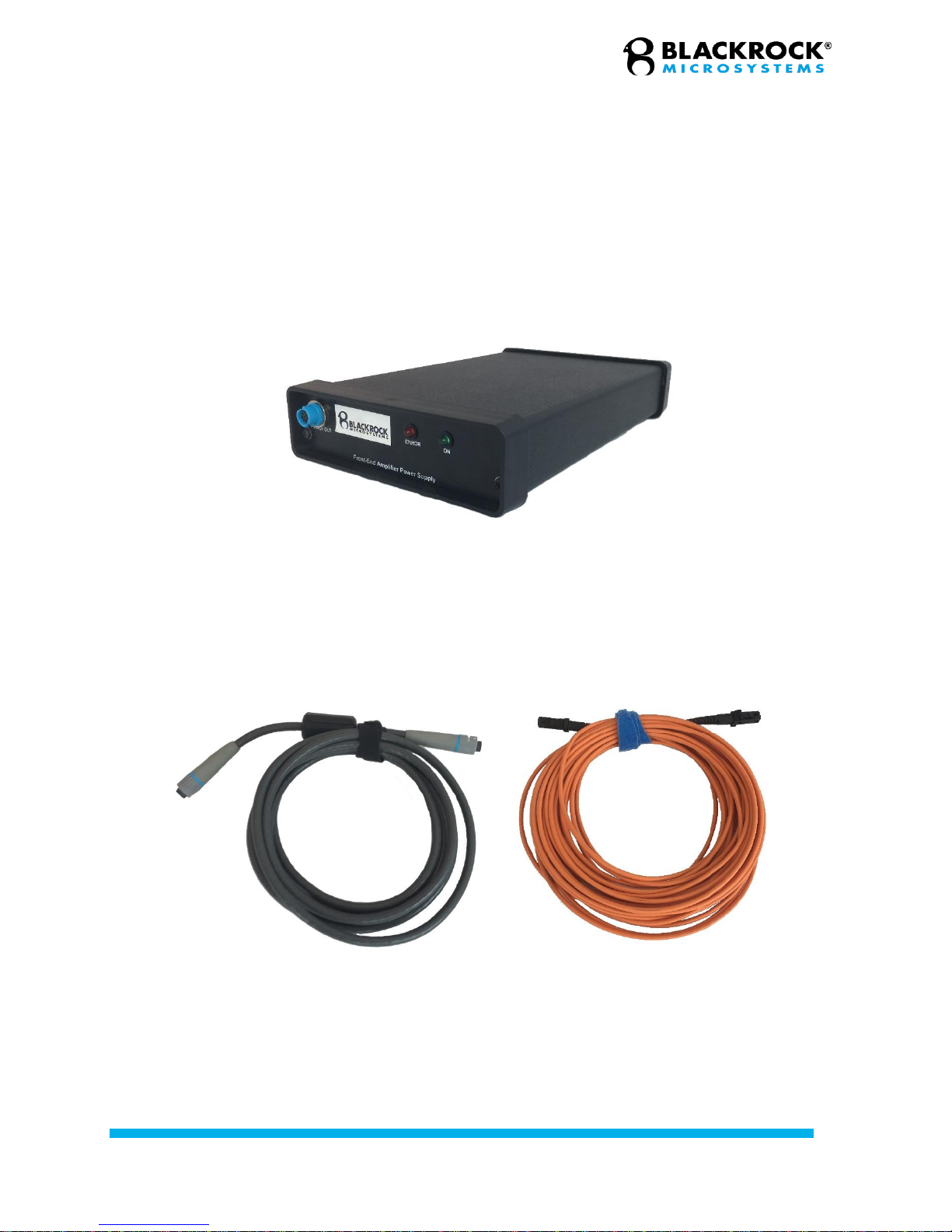
Cables and Connectors
Figure 4—Amplifier power supply cable (left) and fiber-optic cable (right)
Included is a power cable for the NSP, a power cable for the APS, a cable that connects the APS
to the Amplifier, and a fiber-optic cable that connects the amplifier to the NSP.
Figure 3—Amplifier Power Supply (bottom)

Revision 5.00/ LB-0323 –NeuroPort Quick Guide
© 2018 Blackrock Microsystems, LLC
14
Digital Neural Signal Simulator (DNSS)
Figure 5—Digital Neural Signal Simulator
The Digital Neural Signal Simulator (DNSS) is an optional accessory to the NeuroPort system that
supplies simulated field potentials and action potentials (spikes) as well as sine waves at different
frequencies. It can be used to test a recording system in lieu of being connected to a subject.

Revision 5.00/ LB-0323 –NeuroPort Quick Guide
© 2018 Blackrock Microsystems, LLC
15
Software Setup
A crossover Ethernet cable is needed to connect the host PC to the NSP. The computer needs to
be configured to connect to the NSP. Under Network and Adapter Settings, Select Change
Adapter Settings, then open Properties for the appropriate ethernet port. Uncheck all services
except for Internet Protocol TCP/IPv4 (Figure 6, left). Click on Internet Protocol TCP/IP and click
on Properties. For IP Address enter 192.168.137.1, for Subnet Mask enter 255.255.255.0 and
leave the rest blank (Figure 6, right). Save changes.
Once the ethernet port is configured as specified above, you may run the Central installer
executable and connect to the NSP.
Figure 6—Ethernet port configuration

Revision 5.00/ LB-0323 –NeuroPort Quick Guide
© 2018 Blackrock Microsystems, LLC
16
Software Overview
Installation
To install the software suite, run NeuroPort Central Suite.msi from the supplied CD and follow the
onscreen instructions.
Central
Central, Figure 7, is the main control app for NeuroPort Central Suite. From this app, the user
may access all of Central’s utilities. To run Central, click on Start and navigate to the program’s
folder and click on the Central shortcut.
Hardware Configuration
The Hardware Configuration panel, Figure 8, contains individual channel configurations as well
as system settings. The main panel displays channels in icon or list view as selected in the tool
bar. Double clicking selected channels will open the channel properties window for editing.
Channels are filtered by clicking the categories listed on the left pane of the window. Additional
settings are found under the Settings heading at the bottom of the left pane.
Figure 7 - Central
Figure 8 - Hardware Configuration
Revision 5.00/ LB-0323 –NeuroPort Quick Guide
© 2018 Blackrock Microsystems, LLC
17
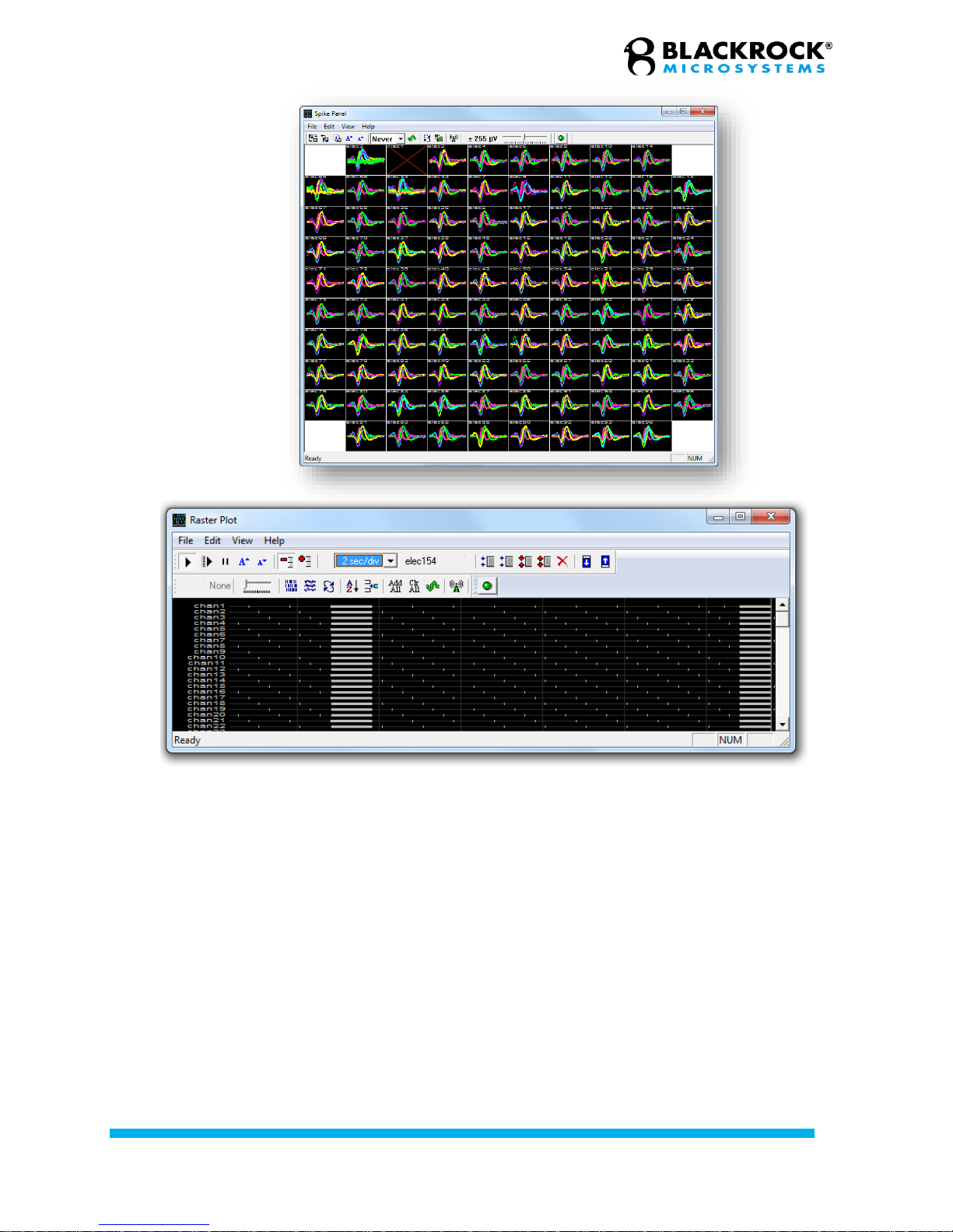
Spike Panel
This Panel displays spike activities for all electrodes across the array. Array mapfiles (.cmp files)
may be loaded in this panel to configure the display to match the electrode geometry.
Raster Plot
The Raster Piot utility displays the data stream for all front-end, analog, and digital inputs. This
utility may be configured to show the continuous trace, or spike event markers.
Figure 9—Spike Panel (top) and Raster Plot
(bottom)
Revision 5.00/ LB-0323 –NeuroPort Quick Guide
© 2018 Blackrock Microsystems, LLC
18
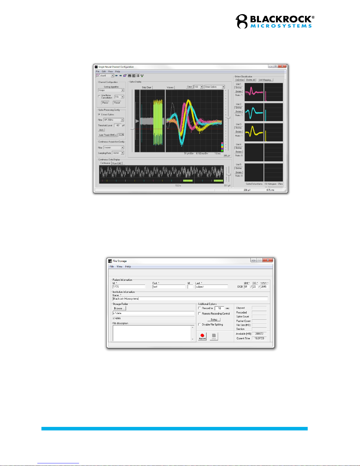
Single Neural Channel
This utility displays the spike activities and the continuous signals for individual channels. The
user can graphically configure spike thresholds as well as set spike sorting rules for individual
channels.
File Storage
This utility is used to configure, start, and stop file recording. Patient information may be entered
here and saved alongside the data.
Figure 10—Single Neural Channel
Figure 11—File Storage
Revision 5.00/ LB-0323 –NeuroPort Quick Guide
© 2018 Blackrock Microsystems, LLC
19
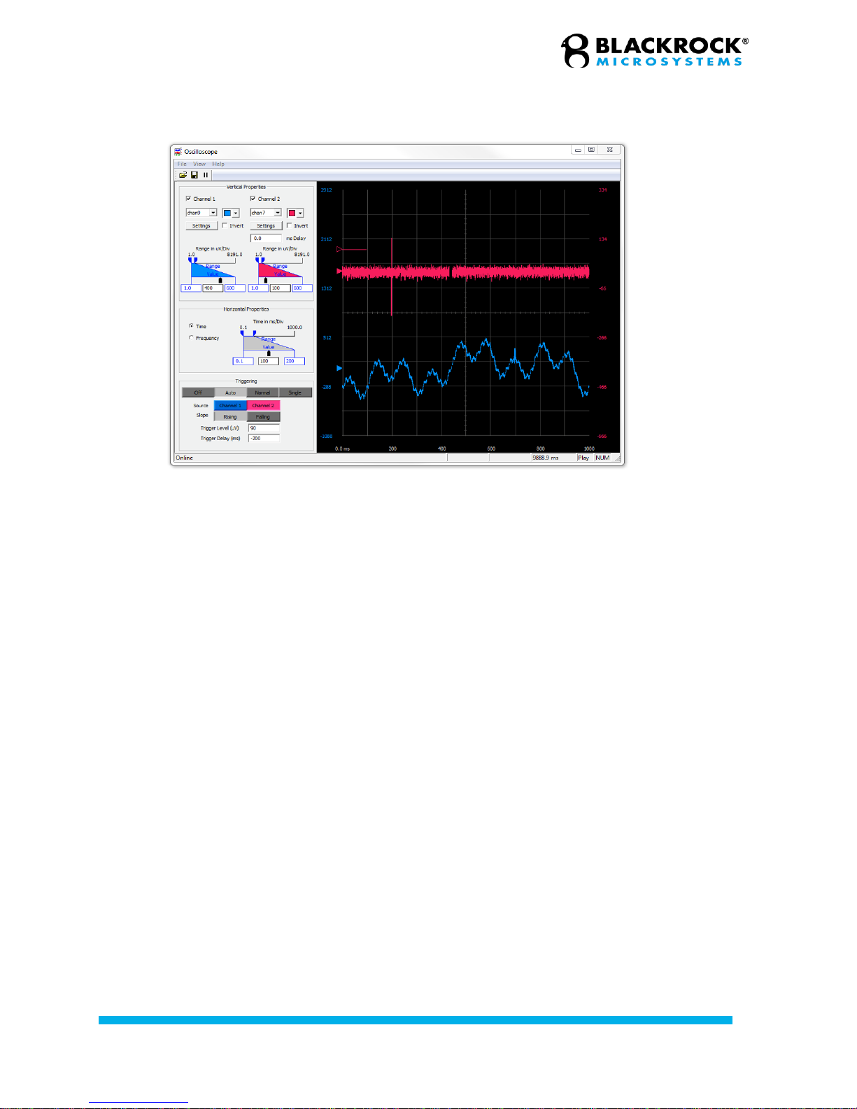
Oscilloscope
The Oscilloscope utility is used to access and configure the NeuroPort digital oscilloscope. The
digital oscilloscope can display and measure two input channels onscreen at a resolution of 0.1
milliseconds per division
Figure 12—Oscilloscope

Revision 5.00/ LB-0323 –NeuroPort Quick Guide
© 2018 Blackrock Microsystems, LLC
20
Digital Filter Editor
This tool is used to design custom digital filters for use in the software. The digital filter editor
requires Matlab Compiler Runtime (MCR) 7.16, which is not installed by default. The MCR 7.16
installer is included on the included software CD, or on the Blackrock Microsystems website at
http://blackrockmicro.com/technical-support/software-downloads/.
Figure 13—Digital Filter Editor
Other manuals for NeuroPort
2
Table of contents
Other Blackrock Microsystems Medical Equipment manuals


Popular Medical Equipment manuals by other brands


Jumper
Jumper JPD-ES100 manual

Boston Scientific
Boston Scientific EASYTRAK 2 IS-1 Physician's lead manual

CEFLA
CEFLA NewTom 5G Vet Attachment Manual

Cincinnati Sub-Zero
Cincinnati Sub-Zero NORM-O-TEMP Operation manuals

CORFLEX
CORFLEX Ranger II GS Application Instructions

Storz
Storz AUTOCON II 400 instruction manual