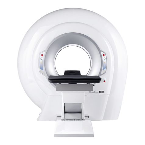
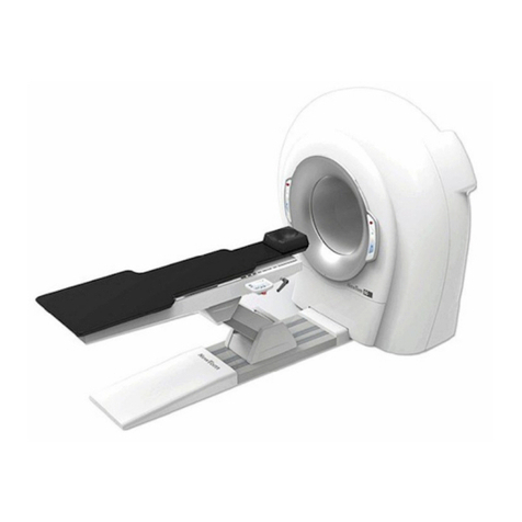
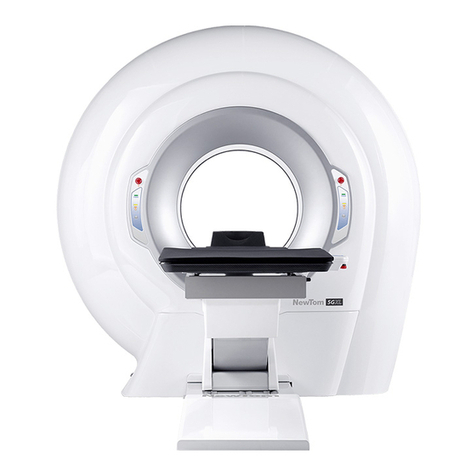
CEFLA NewTom 5G Vet User manual

0051
97050812
Rev. 1 - 28.10.2016
ATTACHMENT to the User Manual
eterinary Application – Attachment

NOTES
This document is provided as a consultation manual intended for the device users.
CEFLA s.c. follows a policy based on the constant development and update of the product. For this reason, it
reserves the right to change the content of this manual without prior notice.
This document can not be modified, copied, reproduced, distributed, saved on magnetic or optical supports,
or published on websites and other on-line services, in full or in part, without the prior written authorisation of
CEFLA s.c.
The original version of this manual is in Italian.
NEWTOM™ 5G is a trademark of CEFLA s.c.
All other products and trade names mentioned in this document are registered marks of the relevant
manufacturers.
INFORMATIVE NOTE OF THE MANUFACTURER ON THE MEDICAL DEVICES
The medical device referred to in this manual consists of a scanner and a control, display and calculation unit
(Main Workstation). Such device, as delivered and configured by the production and assistance technical
personnel, is an X-ray device compliant with the safety requirements set forth by the Italian Legislative
Decree of 19 September 1994, no. 626 implementing Directives 89/391/EEC, 89/654/EEC, 89/655/EEC,
89/656/EEC, 90/269/EEC, 90/270/EEC, 90/394/EEC and 90/679/EEC concerning the improvement of the
health and safety of workers in the workplace, and with the essential requirements set forth by the Italian
Legislative Decree 24 February 1997, no. 46 implementing Directive 93/42/EEC as amended, on the medical
devices.
The medical device referred to in this manual is an X-ray device compliant with Directive 2011/65/EU on the
restriction of the use of certain hazardous substances in electrical and electronic equipment.
Any tampering with, modification, updating or other change both of hardware1 and software2 of the device as
supplied and installed by the company (and in the conditions specified in the attached documentation) may
partially or totally compromise the device expected operation. This may also alter the safety features with
consequent hazard increase for patients, operators and surrounding environment.
For this reason, should the user need to modify the device, he/she must request a written authorisation by
CEFLA s.c.
Failure to comply with what is specified in this informative note will null and void the device warranty and the
civil and/or penal responsibility for any consequent damage and/or accident and/or worsening of the patient,
operator or other people health (including the surrounding environment) will be borne by the person who
tampered with the device or his/her legal representative.
1
Adding of a new memory expansion, a new hardware on the connection bus, a printer, the replacement
of the graphic display interface represents an important modification.
2
Including the operative system and the applications already installed upon medical device delivery.
Automatic updates of the operative system, changes to network connection parameters, modification
and/or addition and/or removal of interface software with hardware device driver) and/or services e.g.
file and printer sharing service) and/or applications represent an important modification.

Summary
1 INTRODUCTION TO THIS MANUAL......................................................................1-1
1.1 Contents........................................................................................................... 1-1
1.2 Structure Of The Manual........................................................................................1-1
1.3 Graphic Conventions............................................................................................. 1-1
2 ABOUT SAFETY............................................................................................2-1
2.1 Local Law......................................................................................................... 2-1
2.2 Sym ols Overview................................................................................................2-1
2.3 Switching ON And OFF The Device.............................................................................2-1
2.4 Emergency Stop.................................................................................................. 2-1
2.5 Safety Of The Animal And The Operator......................................................................2-1
2.5.1 Positioning The Animal ..................................................................................2-2
2.5.2 During The Scan........................................................................................... 2-2
2.5.3 Removing The Animal From The Scanning Area ......................................................2-2
2.5.4 xtracting The Animal In The vent Of The Breakdown / Malfunction Of The Patient Table 2-2
2.6 Artifacts And Repetition Of A Scan............................................................................2-3
2.7 Artifacts And Repetition Of A Scan............................................................................2-3
2.8 Protection From Laser Exposure...............................................................................2-5
2.9 Devices Connected To The Command Console ..............................................................2-5
2.10 Maintenance Time Lag.........................................................................................2-5
2.11 Built-in Parts....................................................................................................2-6
3 SAFETY AND MAINTENANCE OF THE DEVICE.........................................................3-1
3.1 Installation Requirements......................................................................................3-1
3.2 Guidelines For Safety............................................................................................3-1
3.3 Device Modifications............................................................................................. 3-1
3.3.1 Responsibility Limits......................................................................................3-1
3.4 Device Maintenance.............................................................................................3-1
3.5 Cleaning And Disinfection.......................................................................................3-1
3.5.1 Chemical Agents To Avoid................................................................................3-1
3.5.2 Cleaning.................................................................................................... 3-1
3.5.3 Disinfection................................................................................................ 3-2
3.5.4 Sterilization................................................................................................3-2
3.6 Transport And Storage...........................................................................................3-2
3.7 Device Disposal................................................................................................... 3-2
3.7.1 Information For The Device Owner.....................................................................3-2
3.7.2 Information For The Disposing/Recycle Centers.....................................................3-2
3.8 Biocompati ility.................................................................................................. 3-2
4 GETTING STARTED........................................................................................4-1
4.1 Introduction To The System....................................................................................4-1
4.1.1 Intended Use............................................................................................... 4-1

4.1.2 Indications For Use........................................................................................4-1
4.1.3 Improper Use...............................................................................................4-2
4.1.4 Device Operation.......................................................................................... 4-2
4.2 Working Principle................................................................................................4-2
4.3 Overall View...................................................................................................... 4-3
4.4 Scanning Unit..................................................................................................... 4-4
4.4.1 Signalling And Command Keyboards ...................................................................4-4
4.4.2 Main Switch And Input Panel ...........................................................................4-5
4.5 Patient Ta le With Stretcher ..................................................................................4-5
4.5.1 Patient Table With Stretcher Console..................................................................4-6
4.6 Standard Accessories............................................................................................4-8
4.7 Ca les.............................................................................................................. 4-8
4.7.1 Optional Accessories......................................................................................4-8
4.8 System Accessories..............................................................................................4-8
4.9 System Shut Down...............................................................................................4-8
5 PRELIMINARY PROCEDURES.............................................................................5-1
5.1 Daily Check....................................................................................................... 5-1
5.2 Blank Acquisition.................................................................................................5-1
5.2.1 Invalidating The Blank Acquisition.....................................................................5-1
5.3 Beam Limiter Test................................................................................................5-1
6 SCANNING...................................................................................................6-1
6.1 Animal Scan....................................................................................................... 6-1
6.1.1 Animal Preparation.......................................................................................6-1
6.1.2 Positioning The Animal And Starting A New Scan.....................................................6-1
7 QUALITY ASSURANCE.....................................................................................7-1
7.1 Phantom Positioning.............................................................................................7-1
7.2 Images Samples..................................................................................................7-1
7.3 Storage Of QA Data..............................................................................................7-1
TROUBLESHOOTING....................................................................................... -1
9 IEC61223: ACCEPTANCE TEST..........................................................................9-1
10 APPENDIX A- TECHNICAL REFERENCES.............................................................10-2
11 APPENDIX B – SECURITY STANDARDS...............................................................11-1
12 APPENDIX C - LABELS.................................................................................12-1

1 Introduction to this manual
1.1 Contents
This manual has been designed as a consultation resource to provide information and instructions regarding
the use of the NewTom™ 5G series model “NewTom 5G et”
This document is an appendix to the “USER MANUAL”.The routine operation of software envisaged for this
device (scanning, data processing, reporting and managing documents) and the user instructions are
addressed in the “NNT User Manual".
"User Manual" and "NNT User Manual" should be read and clearly understood in every part before starting
using the device.
It is suggested to store this manual along with any other documentation and to use it whenever a new staff
member has to be trained for using the device.
1.2 Structure of the manual
Please refer to the paragraph of the same name in the “User Manual”.
1.3 Graphic conventions
Please refer to the paragraph of the same name in the “User Manual”.
Veterinary Application 1-1

2 About safety
2 About safety
Please refer to the paragraph of the same name in the “User Manual”.
2.1 Local law
Please refer to the paragraph of the same name in the “User Manual”.
2.2 Sym ols overview
Please refer to the paragraph of the same name in the “User Manual”.
2.3 Switching ON and OFF the device
Please refer to the paragraph of the same name in the “User Manual”.
2.4 Emergency stop
The device is supplied with 4 emergency buttons. The first button is installed close to the operator table. The
second button is located on the patient's table below the table control panel. Two additional buttons are
placed on the side of the scanner gantry next to the control panels.
Figure 1: Emergency button on the operator's table
2.5 Safety of the animal and the operator
Operating in the correct mode and positioning the animal correctly avoids risks for the animal and for the
operators involved.
Particular care must be taken with animals with trauma.
Veterinary Application 2-1

2 About safety
2.5.1 Positioning the animal
Ensure that the animal is correctly positioned on the table and no part of its body will bump into the device or
be squashed during the positioning stage.
Ensure that there is no possibility of any animal hair becoming caught.
Carry out the same checks for any catheters, respiratory tubes or ECG (electrocardiograph) cables.
Do not start any movement until you have ensured the safety of the animal and that there is nothing
obstructing the movement of the table itself.
For further details on positioning the animal, please refer to par 6 1 2 - “Positioning the animal and starting a
new scan“
2.5.2 During the scan
Please refer to the paragraph of the same name in the “User Manual”.
2.5.3 Removing the animal from the scanning area
At the end of the examination or after the emergency stop button has been pressed, the patient table can be
extracted from the scanning area and the animal removed.
2.5.4 xtracting the animal in the event of the breakdown / malfunction of the
patient table
In the event of an interruption to the operation of the patient table with stretcher, extract the animal by
manually removing the stretcher completely from the gantry of the device.
2-2 Veterinary Application

2 About safety
NOTES:
For further movement onto a stretcher, if the animal is
unconscious or unable to walk, please refer to the
procedures established by the organisation.
NOTES:
In case of involuntary power supply interruption, the
maximum vales of the distance of motorized patient table
movements (with a maximum rated load applied) are the
following:
Longitudinal Movement: <5mm
Transversal Movement: <10mm
ertical movement: <5mm
2.6 Artifacts and repetition of a scan
Please refer to the paragraph of the same name in the “User Manual”.
2.7 Artifacts and repetition of a scan
WARNING:
NewTom 5G et is a radiological device and therefore it
exposes operators and patients to the risks consequent to
the exposure to ionizing radiation.
It must be used according to safety rules that are
contemplated by the local laws regarding this matter.
WARNING:
NewTom 5G et mustn't be used for routine examinations or
screening.
For this purpose consider other diagnostic tools.
Imaging examinations performed on each patient must be
justified, so that it can be shown that the benefits outweigh
the risks of use.
Always carefully follow the applicable regulations about radio-protection and the directions from a Certified
Radiation Protection Expert.
✔Operator
An operator must oversee the examination process from his/her control position according to the
laws in force; NO ONE SHOULD BE BY THE PATIENT DURING THE EXAMINATION PROCESS.
If a patient panics and an operator's intervention is needed during the examination process, the
operator must be equipped with proper protection clothing and devices, according to the laws.
WARNING:
Never stand close to the device during x-ray emission.
Veterinary Application 2-3

2 About safety
✔Ani al
The operator is responsible for protecting the animal against unnecessary exposure.
✔Devices for viewing e issions
The x-ray emission status is identified by:
1. A signal on the workstation screen such as the one reported below. It appears on video just after
the START command has been selected via keyboard or mouse (see Chapter 6 “Scanning“). It is
displayed all along the scan process.
2. Light indicators (LEDs) inside the control panels. They can be found on the sides of the scanner
gantry. They light on just after the START command has been sent via keyboard or mouse (see
Chapter 6 “Scanning“). They stay on all along the scan process or emission.
WARNING:
If the x-ray emission signals are on when the specific command
has not been selected or if they are off after a START emission
command or if the x-ray emission does not stop after the
expected time, IMMEDIATELY TURN THE DE ICE OFF and
2-4 Veterinary Application

2 About safety
contact technical assistance.
2.8 Protection from laser exposure
The device is equipped with dual lasers for the correct positioning of the animal. Laser radiation comes from
two holes located on the inside cover.
The vertical line identifies the central sagittal plane of the reconstructed volume. The horizontal line identifies:
–in case of Large field scan, the occlusal plane.
–In case of other scan modalities, the central axial plane of the reconstructed volume.
WARNING:
Do not stare into the laser beams, do not view directly with
optical instruments, and avoid direct exposure to the beam.
The beams can cause permanent eye damage.
WARNING:
Keep your eyes at least 40mm from the laser when the
beam is on.
If necessary, use appropriate protective glasses.
WARNING:
The use of controls, adjustments, or the performance of
procedures other than those specified herein may result in
hazardous radiation exposure.
2.9 Devices connected to the command console
Please refer to the paragraph of the same name in the “User Manual”.
2.10 Maintenance time lag
Please refer to the paragraph of the same name in the “User Manual”.
2.11 Built-in parts
The parts of the device that during normal use necessarily come into contact with the animal for the device to
be able to perform its functions are: Mat covering the patient table, patient table with stretcher.
Veterinary Application 2-5

2 About safety
Non applied parts that may come into contact with the animal are external covers.
2-6 Veterinary Application

3 Safety and maintenance of the device
Please refer to the paragraph of the same name in the “User Manual”.
3.1 Installation requirements
Please refer to the paragraph of the same name in the “User Manual”.
3.2 Guidelines for safety
Please refer to the paragraph of the same name in the “User Manual”.
3.3 Device modifications
Please refer to the paragraph of the same name in the “User Manual”.
3.3.1 Responsibility limits
Please refer to the paragraph of the same name in the “User Manual”.
3.4 Device maintenance
Please refer to the paragraph of the same name in the “User Manual”.
3.5 Cleaning and disinfection
Please refer to the paragraph of the same name in the “User Manual”.
3.5.1 Chemical agents to avoid
Please refer to the paragraph of the same name in the “User Manual”.
3.5.2 Cleaning
Please refer to the paragraph of the same name in the “User Manual”.
Veterinary Application 3-1

3 Safety and maintenance of the device
3.5.3 Disinfection
Please refer to the paragraph of the same name in the “User Manual”.
3.5.4 Sterilization
Please refer to the paragraph of the same name in the “User Manual”.
3.6 Transport and storage
Please refer to the paragraph of the same name in the “User Manual”.
3.7 Device disposal
3.7.1 Information for the device owner
Please refer to the paragraph of the same name in the “User Manual”.
3.7.2 Information for the Disposing/Recycle centers
Please refer to the paragraph of the same name in the “User Manual”.
3.8 Biocompati ility
Cover the patient support with cloth composed by biocompatible materials, according to standard ISO 10993
3-2 Veterinary Application

4 Getting started
4 Getting started
This chapter provides a brief introduction for the NewTom 5G et system, its power on and off routines and
control devices.
4.1 Introduction to the system
4.1.1 Intended use
The device NewTom 5G et is a cone beam computed tomography x-ray system. It is intended for diagnostic
use obtaining geometric information and radiologic density from two-dimensional and three-dimensional
images of anatomic particulars and objects in the examined area.
4.1.2 Indications for use
The NewTom 5G et is a cone beam computed tomography x-ray imaging system that acquires sequences
of images within anatomical regions of interest according to system specifications.
The device accomplishes this task by reconstructing a three dimensional matrix of the examined volume and
producing two dimensional views of this volume, displaying both two and three dimensional images.
The device is operated and used by x-ray technologists, and licensed veterinary professionals and other
legally qualified professionals.
This device is for eterinary Use Only.
WARNING:
NewTom 5G et is able to produce panoramic reconstructions
from CBCT acquisitions. This may reduce dose in the case
where both CBCT and panoramic images are needed. However,
if the system is used to simulate a panoramic image when a
CBCT is not necessary, this can lead to excess radiation dose to
the patient.
WARNING:
Federal law restricts this device to sale by or on the order of a
practitioner licensed by the law of the State in which he practices
to user or order the use of x-ray imaging systems
21CFR801.100(b)
WARNING:
Cone beam imaging should not be used for 'routine' (or
'screening') examinations.
Other diagnostic tools must be considered. The imaging
examinations must be justified for each patient to demonstrate
that the benefits outweigh the risks.
Veterinary Application 4-1

4 Getting started
4.1.3 Improper Use
The NewTom 5G et device has not been designed for the following uses and/or applications (reasonably
foreseeable improper use):
–use with animal that cannot stand still during the entire scanning cycle (30 seconds max.);
–use with animals that cannot be secured during scanning;
–use with animals of weight and dimensions exceeding the specifications for the device: animals lying
on the bed weighing over 160 kg, animals whose body parts do not fit in the gantry (diameter 580
mm);
–use by staff that have not received training on the device;
–use by staff that do not meet the requirements specified in the user profile;
use with removable metal objects (collars) in the scanning field;
–use in environmental conditions other than the indicated ones.
4.1.4 Device Operation
Please refer to the paragraph of the same name in the “User Manual”.
4.2 Working principle
Please refer to the paragraph of the same name in the “User Manual”.
4-2 Veterinary Application

4 Getting started
4.3 Overall view
The system is composed by three main parts: scanner unit, patient table accessory (patient table version,
cod. 96600722 or patient table with stretcher version, cod. 96600822) and ain workstation installed out of
the patient area.
It is also possible to add more workstations for data processing and storage.
For additional informational about this matter, please refer to the "NNT User Manual".
NOTE:
The system may not be expanded with parts or accessories
other than the ones described inside this manual
Veterinary Application 4-3
Figure 2: NewTom 5G Vet complete system

4 Getting started
4.4 Scanning unit
4.4.1 Signalling and command keyboards
The scanning unit, called Scanner, is the centre of the system.
At the sides of the scanning hole, on the circular ring shaped cover, there are two keyboards for the lights
that indicate the device is switched on and the status of x-ray emissions.
Also located on the keyboards is the power button for the laser modules to be used during patient
positioning.
Next is a brief description of each button and sign:
E ergency button:
to be used only during danger situations.
To restore the default condition after pressing the button,
rotate it in the direction indicated by the arrows.
Power ON indicator:
A green LED turns on after the device has been switched ON
by pushing the main switch located on the input panel.
X-Ray e ission indicator:
A yellow LED will turn on during ray emission from the device.
Laser Button(L):
Turns the positioning laser beam on/off. The laser will light up
for about 60 seconds.
4-4 Veterinary Application
Figure 3: Scanner unit keyboards

4 Getting started
4.4.2 Main switch and input panel
Please refer to the paragraph of the same name in the “User Manual”.
4.5 Patient ta le with stretcher
The patient table with stretcher is the system accessory used for the positioning of the animal.
Located on a special arm is the control button for moving the table; and the lights indicating that the device is
switched on, that x-rays are being emitted, and the possible activation of the emergency button.
The button panel also houses the power button for the laser modules to be used during the positioning of the
animal.
Veterinary Application 4-5

4 Getting started
4.5.1 Patient table with stretcher console
Figure 3: Patient table with stretcher console
Button Function Warnings
UP/DOWN Raise and lower the table These movements are not allowed in case of
"facilitated uphill position".
The minimum / maximum excursions of the
movements are limited to defaults values by
active collision controls.
FORWARD/BACK Not available Not available. Physically, the stretcher can
be moved only in manual mode
LEFT/RIGHT
Transversal movement Transversal table movement is not allowed in
case of "facilitated uphill position". The
minimum / maximum excursions of the
movements are limited to defaults values by
active collision controls.
P1 Start sequence
"Exam Preparation Position"
Operation allowed when the display show a
window with P1 symbol (ie if the stretcher is
completely out of the gantry with active limit
switch).
4-6 Veterinary Application

4 Getting started
P2 Start sequence
“Facilitated Uphill Position”
Operation allowed when the display show a
window with P2 symbol (ie if the stretcher is
completely out of the gantry with active limit
switch).
+ / -
+ / - buttons
The function depends on the current page
displayed on the screen
LASER Laser ON / OFF buttons The button is active only if the
communication 5G / PC is active
F1 / MODE / F2 Navigation menu buttons
F1 / MODE / F2
The function depends by the icon displayed
on the screen in correspondence of the
relevant key
READY 5G/PC connection Led A green LED is on when the connection
between 5G and PC is active
X-RAY EMITTION X-ray emission Led A yellow LED is on when an x-ray emission
is active
FAULT Fault Led A red LED is on when when an anomaly
occurs. The operator attention is required
For more details about the use of patient table and complete available buttons and functions, please refer to
the “Patient Table User Procedures” document.
Veterinary Application 4-7
Table of contents
Other CEFLA Medical Equipment manuals

CEFLA
CEFLA NEWTOM 5GXL User manual

CEFLA
CEFLA NewTom GiANO HR User manual

CEFLA
CEFLA NewTom 5G Series User manual

CEFLA
CEFLA NewTom VGi evo User manual

CEFLA
CEFLA NewTom GiANO HR User manual

CEFLA
CEFLA MyRay Hyperion X9 User manual

CEFLA
CEFLA NEWTOM 5GXL User manual

CEFLA
CEFLA NewTom 5G User manual

CEFLA
CEFLA NewTom 5G Series User manual

CEFLA
CEFLA GiANO HR User manual