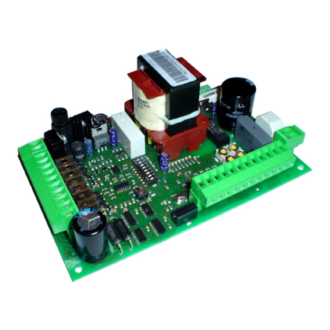
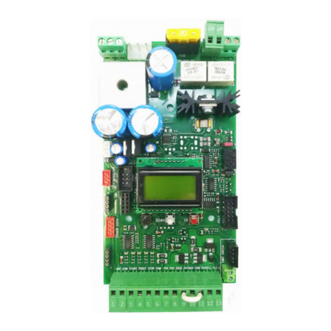
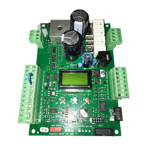
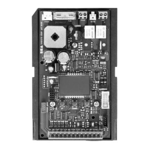
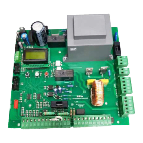
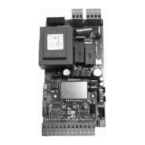
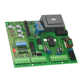
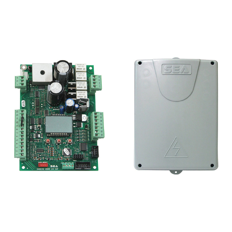
SEA GATE 2 User manual

REV 04 - 11/2006
Automazione
Porte e Cancelli
GATE 2 - 24V PLUS
SEA (UK) Limited
Unit 6A Olton Wharf, Solihull B92 7RN
Tel. 0121 706 9629 - Fax 0121 764 56034
London Tel. 0208 360 8022
www.seaukltd.co.uk
e-mail: [email protected]
67410192
ELECTRONIC CONTROL UNIT FOR SWING OPERATORS 24 V D.C.
English
Deutsch
23001135

CONNECTIONS
GATE 2 - 24V PLUS
REV 04 - 11/2006
Automazione
Porte e Cancelli
CN1
1 2 3 4 5 6 7 8 9 10 1112
START
START Ped.
CN3
1 2 3 4 5 6 7 8 9 10
STOP
GND
CN4
Battery 24Vdc
1 2
M2
~
M1
~
CN2
1 2
GND
+-
24V TXPhotocell
+12V Electriclock
Flashinglamp24V 15W
-+
24 Vdc Accessoires
2
Common
PHOTOCELL
LIMITSWITCHOp1
LIMIT SWITCH Cl1
LIMIT SWITCH Op2
LIMIT SWITCH Op2
GND
POWERSUPPLY
AERIAL
230V ACINCOMING

GATE 2 - 24V PLUS
REV 04 - 11/2006
Automazione
Porte e Cancelli
F1
CN4
CN3
P1
DIP
CN1
Rv1
Rv2
Rv3
Rv4
RX CN2
T1
LED1
LED10
LED6
LED5
LED4
LED3
LED2
LED9
LED8
LED7
3
LED1 = Programming Tx/selflearning / LED2 = Photocell / LED3 = Start / LED4 = Stop / LED5 = Start pedestrian / LED6 = Limit switch
opening motor 2 / LED7 = Limit switch closing motor 2 / LED8 = Limit switch opening motor 1/ LED9 = Limit switch closing motor 1 /
LED10 = Power supply / F1 = Fuse battery charge 250mA / RX = 433 Mhz receiver module CN1 = Connector for entries / CN2 = 230V
power supply connector / CN3 = Connector for exits / CN4 = Battery connector / Rv1 = Anti crush sensitivity adjustment / Rv2 = Speed
adjustment of leaves/ Rv3 = Leaf delay adjustment in closing /Rv4 = Pause time adjustment/ P1 = Push button for working time and
radio transmitter memorization / DIP = Dip-switch / T1 = Transformer
DESCRIPTION OF THE COMPONENTS
GB

REV 04 - 11/2006
4
GATE 2 - 24V PLUS
Automazione
Porte e Cancelli
GENERAL INFORMATION ...........................................................................................................5
START, STOP, PEDESTRIAN START, ANTENNA CONNECTIONS ............................................6
PHOTOCELLS, LIMIT SWITCH CONNECTIONS ........................................................................7
ELECTRIC LOCK, FLASHING LAMP, RECEIVER CONNECTIONS ..........................................8
POWER SUPPLY AND MOTORS ARM - ALPHA - BETA CONNECTIONS................................9
RADIO TRANSMITTER TYPE SETTING (DIP-SWITCH)..........................................................10
WORKING MODE SETTING (DIP-SWITCH)..............................................................................10
FUNCTION LOGIC SETTING (DIP SWITCH).............................................................................11
ADDITIONAL FUNCTIONS (DIP-SWITCH) ................................................................................11
SENSITIVITY REGULATION OF AMPEROMETRIC SENSOR..................................................12
MOTOR SPEED ADJUSTMENT.................................................................................................12
LEAF DELAY ADJUSTMENT IN CLOSING ................................................................................12
PAUSE TIME ADJUSTMENT......................................................................................................12
LEDS DESCRIPTION 12
SELFLEARNING WORKING TIMES ..........................................................................................13
RADIO TRANSMITTER SELFLEARNING .................................................................................14
ALARMS AND MAINTENANCE DESCRIPTION ........................................................................14
TROUBLE SHOOTING ..............................................................................................................15
INSTRUCTIONS AND GUARANTEE..........................................................................................16
INDEX
English

GATE 2 - 24V PLUS
REV 04 - 11/2006
Automazione
Porte e Cancelli
GENERAL INFORMATION
GENERAL CHARACTERISTICS
The GATE 2 24V control unit has been designed to manage one or two low voltage swing gate operators with or without
electronic limit switches.
Its dimensions are very sma
matically.
ll and as well as the classic functions refered to by the dip-switch it has several other
features such as motor speed adjustment, amperometric sensitivity for anti crush, adjustment of leaf delay in closing
and alteration of pause time .
The self- learning of working tims is done auto
TECHNICAL CHARACTERISTICS
Control unit power supply
Absorbt power
Max. motor charge
Max. accessories charge
Max. Flash light charge
Environment temperature
Protection fuse (24V accessories)
Function logic
Opening/closing time
Time of pause
Thrust
Slow down
Entries on connecting terminal
Exit on connecting terminal
Board dimensions
Characteristics optional batteries
Characteristics of external enclosure
230V ~
10 W
70 W x 2
24Vdc 200mA
24Vdc 15W max.
-20°C +50°C
1 (250mA)
Automatic / Manual / Security / Dead man
In selflearning in programming phase
Adjustable with trimmer
In selflearning in programming phase
Battery power supply / Total opening /pedestrian
opening / Security /
Stop / limit switch opening and closing
Power supply accessories 24Vdc / Motors 24Vdc /
Flashing lamp 24Vdc / Electric lock 12Vdc /
Power supply TX photocell
156 x 100 mm
12V - 4 Ah / dimensions 90 x 70 x 108 mm
305 x 225 x 125 mm - Ip55
(+6 -10%) - 50/60 Hz
ARRANGEMENTS
For Health and Safety reasons it is important to carefully follow all advice and instructions in this manual. An
incorrect installation or a wrong use of the product can cause injury to persons.
Make sure that the installation has an adequate differential switch as prescribed by the law in force and local isolation at
the control panel.
For the installation of the electric cables use adequate rigid and/or flexible ducts.
Always separate the connection cables of low voltage accessoires from those of 115/230V~ power supply. To avoid any
interference use separate casings.
2
Max. length of the power supply cable between control unit and motors is 10m, using cables with 2,5 mm
section. 5

START (N.O.)
An impulse given to this contact opens and closes
the automation depending on logic selected. It can
be given by a key switch, a keypad, etc.
To connect the other devices refer to the related
instructions leaflets. (ie. loop detectors and
proximity switches)
PEDESTRIAN START (N.O.)
To obtain partial opening (only one leaf opening) connect the key-
switch wires as in the picture. It is possible to connect other
command devices (push button board, radio receiver, keypad).
Note1: The contact for partial opening is a N.O. Contact (Normally
open)
Note2: Partial opening will always operate the M1 motor.
3
10
1
START - STOP - PEDESTRIAN START - ANTENNA
GATE 2 - 24V PLUS
REV 04 - 11/2006
Automazione
Porte e Cancelli
CN1
CN1
1 2 3 4 5 6 7 8 9 10 11 12
STOP (N.C.)
The pressure on this button immediately stops the motors in any
condition /position. A start command is needed to re-start movement.
.
Notice: If stop button not used a link is required between terminals n° 2
and 10.
ANTENNA
Connect the antenna
as in the picture.
11
12
10
2
10
-
6
-
N.O.
N.O.
N.C.
-
-
-

-+ +C C
Photocells 1 Connection
When the photocells beam is crossed, the
automation reverses its movement if in
closing phase.
To use photocell self-testing, connect positive
(+) to terminal 5 instead of 10 (CN3).Tx only
Notice: If photocell not used a link is
required between terminals 5 and 10
(CN1).
+ = 24Vdc - = 0Vdc C = Contact
RX
TX
+-
910
5
PHOTOCELLS/LIMIT SWITCH
GATE 2 - 24V PLUS
REV 04 - 11/2006
Automazione
Porte e Cancelli
CN1
CN1
1 2 3 4 5 6 7 8 9 10 11 12
CN3
CN3
1 2 3 4 5 6 7 8 9
10
8
10
10
Limit Switch 1 M2
Limit Switch 2 M2
Limit Switches
They can be of different types:
- inductive limit switch
- mechanical limit switch with lever
- limit switch with spring
- limit switch for motor-reducer with chain.
All these limit switches must be manufactured by
SEAfor compatibility with the connectors
Com = Common
N.B. If limits not used a link is required between
terminal 6 to 10.
10
10
Limit Switch 1 M1
Limit Switch 2 M1
+-
Photocell
self-testing
+-
Com
N.C.
CCom
+
9
6
7
7
Com
Com
Com
Com
C
C
C
C
Limit Switches
They can be of different types:
- inductive limit switch
- mechanical limit switch with lever
- limit switch with spring
- limit switch for motor-reducer with chain.
All these limit switches must be manufactured by
SEAfor compatibility with the connectors
Com = Common
N.B. If limits not used a link is required between
terminal 8 to 10.

Electric lock exit
An electric lock of 12Vdc 15W max can be
connected .
The electric lock activates at every
opening cycle for about 1,5 sec. 8
6
ELECTRIC LOCK/FLASHING LAMP/
RECEIVER
GATE 2 - 24V PLUS
REV 04 - 11/2006
Automazione
Porte e Cancelli
C C
CN3
CN3
1 2 3 4 5 6 7 8 9
10
Flashing Lamp 24V 15W
The flashing lamp gives warning that the gate is moving.
To connect, wire the flashing lamp as in the picture.
It is possible to activate a pre-flashing of 3 seconds (Dip 8
to ON position).
7
8
+ + -
Connection of a radio
receiver
This connection allows
full opening/closing of
the automation. For the
receiver connection
make reference to the
r e l a t e d i n s t r u c t i o n
manual.
+ = 24Vdc,
- = 0Vdc,
C = Contact NO
Com = Common
1
4
10
9
+
-
CN1
1 2 3 4 5 6 7 8 9 10 11 12
C
CN1
8
+
+
-
-
-
+
Com

CN3
1 2 3 4 5 6 7 8 9
10
Motor 2
Output for Motor 2
connection
M+ = OPEN/CLOSED
M- = CLOSED/OPEN
M1
M2
Power input
Input for the connection of the electric power.
P = PHASE - LIVE
N = NEUTRAL NOTICE: for the connection to the
electric power see the law in force.
2
1
9
POWER SUPPLY - MOTORS ARM-ALPHA-BETA
GATE 2 - 24V PLUS
REV 04 - 11/2006
Automazione
Porte e Cancelli
C C
CN3
CN2
CN2
1 2
ARM
3
4
M+
PN
3
4
3
4ALPHA STD
BETA
ARM
1
2
BETA
1
2
1
2
M+
M- M-
ALPHA STD
ALPHA PLUS
Motor 1
Output for Motor 1
connection
M+ = OPEN/CLOSED
M- = CLOSED/OPEN
ALPHA PLUS
3 4 5 6 7 8 9 10 11 12
CN1
Com
C C
CN1
C C

DIP-SWITCH (TYPE OF RADIO TRANSMITTER)
GATE 2 - 24V PLUS
REV 04 - 11/2006
DIP
DIP
Automazione
Porte e Cancelli
ON
1 2 3 4 5 6 7 8
POSITION
OFF / OFF
ON / OFF
SETTING DIP1 AND DIP2 ACCORDING TO THE TYP OF RADIO TRANSMITTER USED
Radio transmitter SMART Dip-switch and/or radio transmitter HEAD Dip-switch
Radio transmitter SMART Fixed code and/or radio transmitter HEAD Rolling code
DIP
1 / 2
1 / 2
ON
ON / ON
Radio transmitter HEAD e-copy
Erase the radio transmitter*
2
1 / 2
*Modality to erase learned radio transmitter.
Set the Dip 1 and 2 on ON.
Press and keep pressed P1 of the control unit for 10 seconds, the LED will switch on to confirm the executed cancellation.
Bring back the dip-switches into the position regarding the type of transmitter to be memorised.
P1
DIP-SWITCH (OPERATION MODE)
POSITION
OFF / OFF
ON / OFF
SETTING OF DIP6 AND DIP7 RESPECTIVELY THE DESIRED WORKING MODE
Position to select the operational mode: two motors with limit switch
Position to select the operational mode: only one leaf with limit switch (M1)
DIP
6 / 7
6 / 7
OFF / ON
ON / ON
Position to select the operational mode: two leaves without limit switch (see note)
Position to select the operational mode: one leaf without limit switch (M1) (see note)
6 / 7
6 / 7
2. Switch on the power keeping push button P1 on the board pressed continuously.
3. The LED blinks slowly to confirm the memorisation of the operational mode.
4. Switch off the board and reset Dip 6 and 7 to OFF position. Now start self learning mode as explained on the next page.
Note:
To use the board without limit switch it is neccessary to bridge the limit switch inputs in closing to common
(Terminals 6 to 10 for single leaf operation and terminals 6 and 8 to 10 for paired operation).
1. ATTENTION! With power switched off, choose the type of gates (one or two motors) and if limit switches are
fitted, select the operation mode using DIP 6 and 7 and program as below. When set proceed with self-learning.
10
!

MANUAL LOGIC
A start impulse opens the gate. A second impulse during opening stops the movement. A start impulse during closing stops the
movement.
SECURITY LOGIC
A start impulse opens the gate. A second impulse during opening reverses the movement. A start impulse during closing reverses
the movement.
DEAD MAN LOGIC
The gate opens when the push button for opening is pressed and held (connectors 1 and 4 of CN1); releasing it stops the gate. The
gate closes when the push button for closing is pressed and held(connectors 3 and 4 of CN1); releasing it stops the gate. To
execute complete opening and/or closing cycles it is necessary to keep the relative push buttons constantly pressed.
AUTOMATIC LOGIC
A start impulse opens the gate. A second impluse during opening will not be accepted. An impulse during the pause closes the gate
immediately.An impulse during closing reverses the movement.
DIP-SWITCH (FUNCTION LOGIC)
GATE 2 - 24V PLUS
REV 04 - 11/2006
DIP
DIP
Automazione
Porte e Cancelli
ON
1 2 3 4 5 6 7 8
P1
POSIZIONE
ON / ON
ON / OFF
SETTING OF DIP6 AND DIP7 TO SELECT THE FUNCTION LOGIC
Position to select the function logic: MANUAL
Position to select the function logic: SECURITY
DIP
6 / 7
6 / 7
OFF / ON
OFF / OFF
Position to select the function logic: DEAD MAN
Position to select the function logic: AUTOMATIC
6 / 7
6 / 7
DIP-SWITCH (OTHER FUNCTIONS)
ON
ON
PROGRAMMING OF OTHER DIPS FOR OTHER FUNCTIONS
INVERSION STROKE
This function should only be used on swing gates, and is designed to assist the release of the electric
lock.
At the start impulse the motors are powered closed for 1 sec, before starting the opening cycle.
CONTROL OF PHOTOCELL IN OPENING
The interruption of the photocell circuit stops movement, re- opening immediately on reinstatement.
DIP
3
4
ON
PHOTOCELL SELFTEST
If you activate this function it will start a test on the photocells before the gate begins to move. In
order to use this function the photocells transmitters must be connected to the terminals No. 5 and
No. 8 (Negative) of Cn3 connector.
5
ON
PREFLASHING
If you activate this function the flash and the pilot light start flashing approximately 5 seconds before
motor starting up; both in closing and in opening.
8
11

TRIMMER ADJUSTMENT
GATE 2 - 24V PLUS
REV 04 - 11/2006
Automazione
Porte e Cancelli
-
SENSITIVITY ADJUSTMENT OF THE AMMETRIC SENSOR (anti crush)
This adjustment must be made so to avoid the danger of crushing persons or objects and must respect the laws in
force.
MOTOR SPEED ADJUSTMENT
This trimmer allows to adjust the motor speed.
This adjustment must be made to avoid the danger of crushing persons or objects and must respect the laws in force.
ADJUSTMENT OF LEAF DELAY IN CLOSING
This trimmer allows to adjust the dephasing of the leaves in closing from 0 to 112 sec.
TIME OF PAUSE ADJUSTMENT
This trimmer allows the linear adjustment of the time of pause from 0 to 120 sec.
Rv4
Rv3
Rv1
Rv2
Rv1
+
-
NOTE:
TURNE THE I
TRIMMER
CLOCKWISE
TIMES / VALUES
INCREASE
Rv2
Rv3
Rv4
-
LED DESCRIPTION
LED10
LED1
LED9
LED8
LED7
LED6
LED5
LED4
LED3
LED2
LED1: Transmitter programming and self learning.Illuminates during transmitter programming and during the
self learning working times system. It also signals the motors irregular absorption or the Mosfet breaking.
LED2: Photocell.Normally illuminated, switching off when the photocell is obscured.
LED3: Start. Normally switched off, illuminating when you give an opening impulse.
LED4: Stop. Normally illuminated, switching off when you give a stop impulse.
LED5: Pedestrianstart. Normally switched off, illuminating when you give a pedestrian opening impulse.
LED6 and LED7: Motor 1 opening and closing limit switch.Normally illuminated, switching off when the motor 1 limit
switches are activated.
LED8 and LED9: Motor 2 opening and closing limit switch.Normally illuminated, switching off when the motor 2 limit
switches are activated.
LED10: Power supply. Illuminated when power is connected to the control panel.
Rv1
Rv2
Rv4
12
Rv3

M2M1
Fig. 2
Fig. 1
OFF
Fig. 7
ON
2
1
WORKING TIMES SELF LEARNING
GATE 2 - 24V PLUS
REV 04 - 11/2006
Automazione
Porte e Cancelli
Check that each accessory (photocells, push buttons, and so on) work properly and
adjust the leaf delay if necessary.
Disconnect the power supply (Fig. 1), release the motors (Fig. 2-3) and put the leaves
manually near the stop in closing (Fig. 4).
Reset the mechanical lock (Fig. 5-6)
BETA
Fig. 4
Lock
Release
Fig. 3
Lock
ARM
Fig. 6
Fig. 5
BETA
3
A)Put all the dip switches to OFF position.
B)Connect the control board to the power supply.
C)Press and hold the button P1 for 5 seconds. LED1
switches on.
D) Both the leaves will start closing at lowered
speed. Release button P1
E) When the leaves reach the stop they will
automatically go through an opening cycle at
lowered speed.
P1
LED1
M2M1
LED1
5 seconds
M2M1
F) Wait until the leaves
reach fully open.
Led 1 switches off.
LED1
Self learning has finished.
G)Wait until the pause time finishes for the leaves to reclose.
Note: Self learning can only be undertaken in automatic logic.
H)Select the desired operation logic following the instructions on the next page.
A
B C
F
13
ARM
Release

GATE 2 - 24V PLUS
REV 04 - 11/2006
Automazione
Porte e Cancelli
RADIO TRANSMITTER SELF LEARNING
WARNING: make the radio transmitters programming before you connect the antenna.
1. Push and release P1 button, theLED 1 will flash in order to signal waiting for a code to be associated to the total opening.
2. Push the desired button on the radio transmitter, the LED will stay illuminated to signal the information has been saved.
3. Push and release P1 button, the LED1 will flash in order to signal waiting for a code to be associated with pedestrian
opening.
P1
LED1
LED1
4. At this point you can push the radio transmitter
button and the LED will switch off to signal learning
end, or push P1 again and release if you don’t want to
match a button with the pedestrian function.
Notes:
- Enter radio transmitters learning only when the working cycle stops and the gate is closed.
- It’s possible to memorise up to 10 codes (buttons).
- If you have already memorised all the possible codes, the next transmitter will overwrite the next to the last one (button No. 9 in
order of receipt) for full opening or (button No. 10) if the received code is associated with the pedestrian function.
- If the board receives a code which was already associated to another function it will be updated with the new function.
P1
ALARMS INDICATIONS
Flashing sequence, spaced with a pause of 2 seconds, is shown both on the flash (for 45 seconds approximately) and on the
pilot light (until a new START).
Flashings Number
2
3
Kind of alarm
Photocell
Photocell in opening
Flashings Numberi
4
5
Kind of alarm
Photocell Selftest
Stop
ALARM SIGNALS
1. Motors irregular current absorption or Mosfet breaking (ie. it fails the anticrushing safety).
LED L1 flashes quickly. In order to reset the board function you will need to disconnect the power supply.
In the case of failure due to Mosfet breaking and it is not possible to cancel the alarm you must replace the board.
2. Photocell self test alarm. To clear push the STOP button. If the alarm keeps activating check or, if necessary, replace the
photocells.
MAINTENANCE
Depending on the number of working cycles and the type of gate, it may be necessary to reprogram the panel, the gate may
have a higher resistance to movement, this may result in inconsistent in operation.
14
!

N.B.
Every time an adjustment is made reset the board turning OFF the power for 10 seconds and then turn it back
ON.
The gate opens but
Advises
Problem Found Possibile Cause Solution
Make sure all Safety LED’s are turned ON
All not-used N.C. contacts must have jumpers
Motor doesn't respond
to any START impulse
a) Links missing on one of the
N.C. contacts
b) Burnt fuse
a) Check connections or links
on contacts 2/10 on the CN2,
5/10 on the CN1
Cn1
b) Replace burnt fuse on the
board
Gate doesn't move while
the motor is running
a) The motor is in the released
position
b) The electronic clutches
are not set
c) There is an obstacle
a) Re-lock the motor
b) Adjust electronic clutch using
trimmer Rv1 and Rv2
c) Remove obstacle
Gate doesn't reach the
complete Open / Closed
a)
position
Wrong setting of the limit
switches
b) Error on programming
(page 13)
c) Gate is stopped by an
obstacle
d) The fitting geometry is inadequate
a) Set limit switches
b) Repeat programming as on
page 13
c) Remove obstacle
d) Check fitting geometry following
the operator installation manual
doesn't close
a) The photocell contacts
2/10 and 5/10 are not closed
a) Check LED and links
The gate doesn't close
automatically a) Pause time set to high a) Adjust pause time using trimmer
Rv4
TROUBLE SHOOTING
GATE 2 - 24V PLUS
REV 04 - 11/2006
Automazione
Porte e Cancelli
15

WARNINGS
The electric installation and the functioning logic choice must agree with the laws in force. In any case you must foresee a 16A
and threshold 0.030A differential sw
Materials handling must be made with appropriate vehicles..
itch. Keep the power cables (motors, power supply) separate from the command cables
(push buttons, photocells and so on). In order to avoid any interference it’s preferable to use two separate cables and ducts.
REPLACEMENTS
Any request for spare parts must be sent to:
SEA s.r.l. - Zona Ind.le, 64020 S.ATTO - Teramo - Italia or SEA UK Limited Tel : 0121 706 9629
PRODUCT USAGE
The electronic equipment 23001135 has been designed to be used exclusively as management equipment for sliding gates
automation, swing gates, sectional doors, overhead doors, barriers.
SAFETYAND ENVIRONMENTAL COMPATIBILITY
Disposal of the packaging materials of products and/or circuits should take place in an approved disposal facility.
REGULAR PRODUCT DISPOSAL (electric and electronic waste)
(It’s applicable in EU countries and in those ones provided with a differential rubbish collection)
The brand that you find on the product or on documentation signals that the product must not be disposed off together with
other domestic rubbish at the end of life cycle. In order to avoid any possible environmental or health damage because of the
irregular waste disposal, we ask you to separate this product from other forms of rubbish and to recycle it in a responsible way
in order to provide the sustainable re-use of material resources. Domestic users are invited to contact the retailer where the
product has been purchased or the local office in charge of all the information related to differential collection and recycling of
this kind of product.
STORING
REPLACEMENT AND MAINTENANCE
The replacement and/or putting out of service and/or maintenance of the electronic equipment 23001135 must be made only
and exclusively by authorised and qualified staff.
WARRANTY LIMITS
The warranty form of the electronic equipment 23001135 is valid for 24 months starting from the printed date on the product.
The mentioned product will be considered under warranty if it doesn’t show any damage caused by an irregular use or by any
modification or breaking. The warranty is valid only for the original buyer.
NOTE:THE MANUFACTURER IS NOT CONSIDERED RESPONSIBLE FOR ANY DAMAGE CAUSED BY IRREGULAR,
WRONG OR UNREASONABLE USE.
SEA reserves the right to make any required modification or change to the products and/or to this manual without any
advanced notice obligation.
WARNINGS AND WARRANTY
16
WAREHOUSING TEMPERATURES
Tmin TMax Dampnessmin DampnessMax
- 40°C + 85°C 5% Not condensing 90% Not condensing
REV 04 - 11/2006
GATE 2 - 24V PLUS
Automazione
Porte e Cancelli

Other manuals for GATE 2
2
Table of contents
Other SEA Control Unit manuals

SEA
SEA SWING 2 User manual

SEA
SEA PRE-GATE User manual

SEA
SEA SLIDE NEW MAG User manual

SEA
SEA USER 1 - 24v DG R1 User manual

SEA
SEA GATE 1 DG R2BF User manual

SEA
SEA GATE 1 DG R1 User manual

SEA
SEA SWING 2 DG R2F User manual

SEA
SEA GATE 1 DG R2BF User manual

SEA
SEA GATE 1 DG R2BF User manual

SEA
SEA GATE 1 DG R2BF User manual

SEA
SEA USER 1 - 24v DG R1 User manual

SEA
SEA UNIGATE 1I User manual

SEA
SEA GATE 2 DG R1B User manual

SEA
SEA USER 1 - 24v DG R1 User manual

SEA
SEA Orion User manual

SEA
SEA GATE 1 DG R1 User manual

SEA
SEA GATE 2 User manual

SEA
SEA SLIDE DG R2F User manual

SEA
SEA USER 1 - 24v DG R1 User manual

SEA
SEA USER1-24V User manual