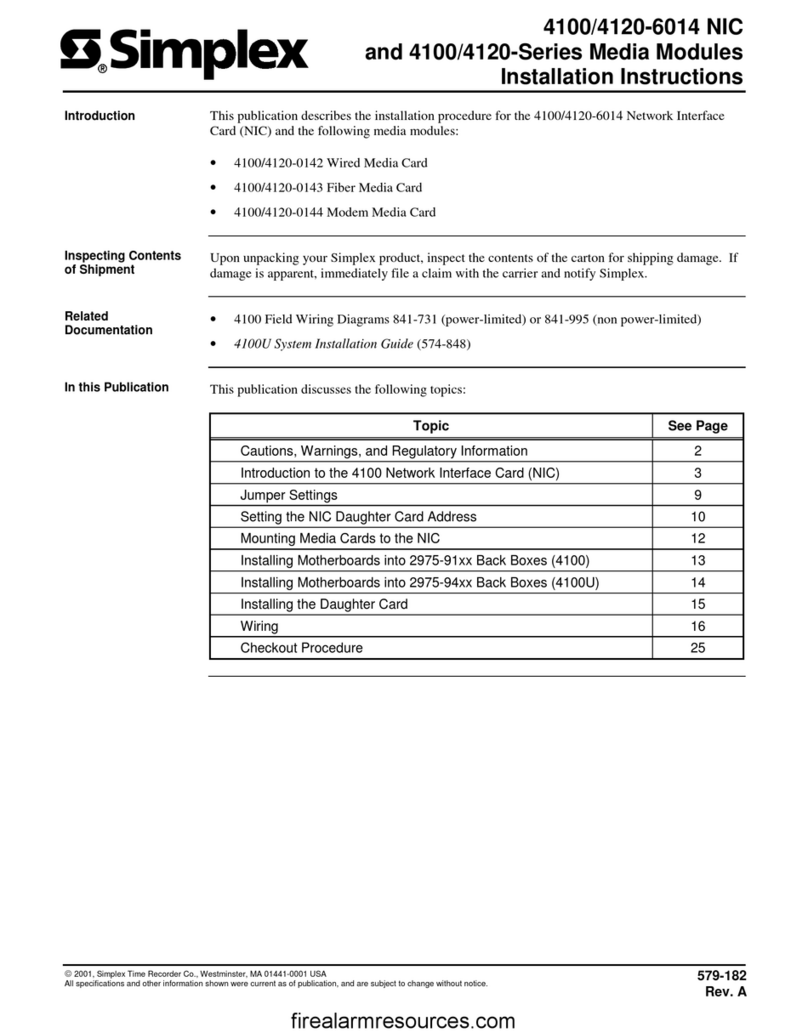
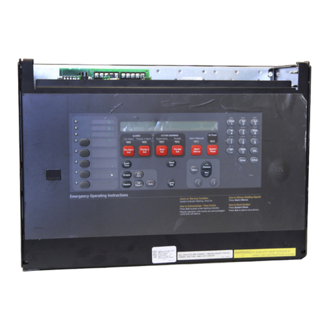
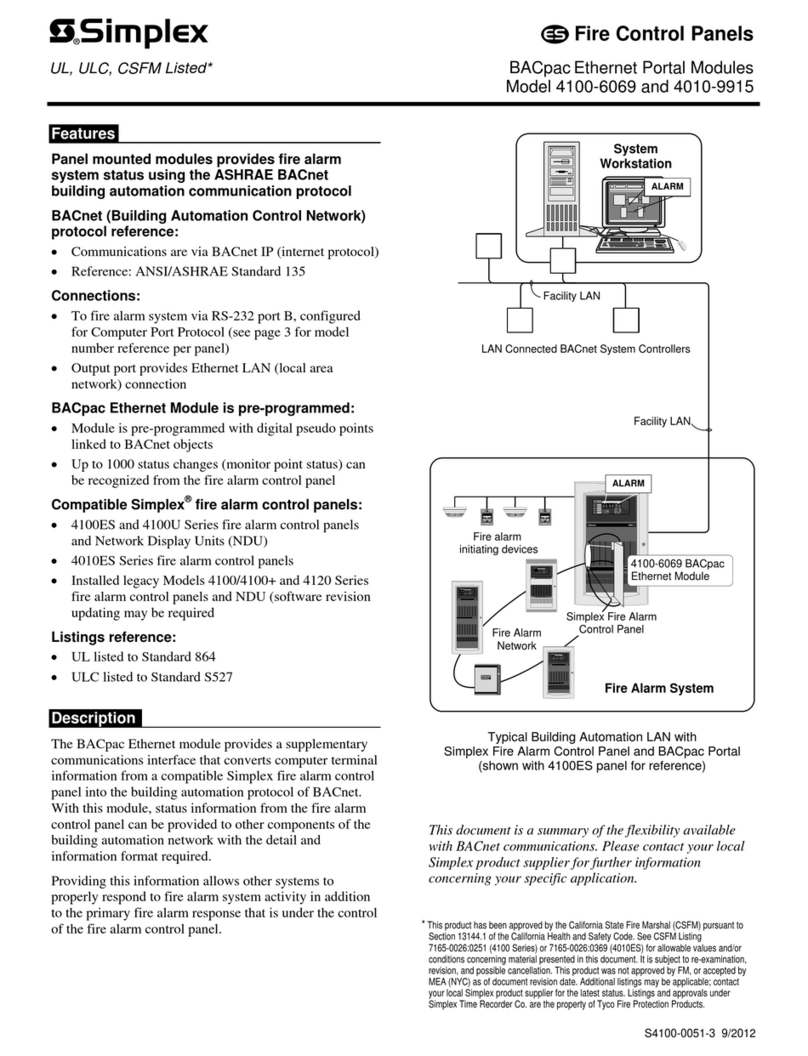
Simplex 2008 Series User manual

2008 Foundation Series Fire Alarm Control
Unit Installation Guide
579-1400 Rev B
*05791400B*

This page is intentionally blank

Contents 1 Cautions, Warnings, and Regulatory Information.....................................................................................3
1.1 FCC Information....................................................................................................................................................................................4
1.2 DACT Wiring overview.......................................................................................................................................................................... 5
2 Overview.........................................................................................................................................................6
2.1 Features.................................................................................................................................................................................................6
2.2 Power supply specifications................................................................................................................................................................7
2.2.1 AC power specification......................................................................................................................................................................................7
2.2.1.1 Replacing the fuse....................................................................................................................................................................................... 8
2.2.2 Battery specification.......................................................................................................................................................................................... 8
2.2.2.1 Replacing the batteries...............................................................................................................................................................................8
3 Installing the FACU........................................................................................................................................ 9
3.1 Unpacking the FACU.............................................................................................................................................................................9
3.2 Determining a suitable location for the FACU.................................................................................................................................. 9
3.3 Mounting the back box........................................................................................................................................................................9
3.4 Connecting conduits.......................................................................................................................................................................... 12
4 Wiring the FACU...........................................................................................................................................14
4.1 Wiring the 2008-9101 FACU.............................................................................................................................................................. 14
4.1.1 Wiring the AC supply and earth ground connection...............................................................................................................................14
4.1.2 Connecting the backup batteries.................................................................................................................................................................15
4.1.3 Connecting the battery harness...................................................................................................................................................................16
4.1.4 Batteries in the external battery cabinet................................................................................................................................................... 16
4.1.5 Enabling the FACU for depleted battery cutout....................................................................................................................................... 17
5 Powering up the system.............................................................................................................................18
6 Product description.................................................................................................................................... 19
6.1 Initiating Device Circuits.................................................................................................................................................................... 19
6.1.1 Wiring IDCs........................................................................................................................................................................................................ 19
6.1.1.1 Wiring Class A IDCs................................................................................................................................................................................... 19
6.1.1.2 Wiring Class B IDCs................................................................................................................................................................................... 20
6.1.1.3 Four-wire base wiring............................................................................................................................................................................... 20
6.1.2 IDC wiring specifications................................................................................................................................................................................ 21
6.2 Notification appliances circuits.........................................................................................................................................................21
6.2.1 Wiring NACs.......................................................................................................................................................................................................21
6.2.1.1 Selecting an end-of-line resistor............................................................................................................................................................22
6.2.1.2 Wiring Class A NACs..................................................................................................................................................................................22
6.2.1.3 Wiring Class B NACs..................................................................................................................................................................................24
6.2.1.4 NAC wiring distance.................................................................................................................................................................................. 24
6.2.1.5 NAC wiring specifications.........................................................................................................................................................................24
6.3 Auxiliary relays....................................................................................................................................................................................25
6.3.1 Wiring an auxiliary relay..................................................................................................................................................................................25
6.4 RS485 Interface...................................................................................................................................................................................26
6.4.1 Wiring an Annunciator....................................................................................................................................................................................26
6.5 Auxiliary power...................................................................................................................................................................................28
6.5.1 Auxiliary power wiring.....................................................................................................................................................................................28
6.6 USB interface...................................................................................................................................................................................... 28
6.7 Digital alarm communicator transmitter.........................................................................................................................................29
6.7.1 Connecting the DACT using telephone lines.............................................................................................................................................29
6.7.2 Connecting the DACT using Ethernet lines and the DSC TL300.......................................................................................................... 30
6.7.3 Connecting the DACT using Ethernet lines and the Bosch C900V2....................................................................................................31
6.8 Optional modules...............................................................................................................................................................................32
6.8.1 City circuit cards............................................................................................................................................................................................... 32
6.8.1.1 Mounting city circuit cards...................................................................................................................................................................... 33
6.8.1.2 Field wiring city circuit cards................................................................................................................................................................... 34
7 Periodic testing and maintenance............................................................................................................ 35
8 Battery calculations.....................................................................................................................................36
8.1 Current draw for system components............................................................................................................................................ 36
9 Annexure A...................................................................................................................................................37
page ii 579-1400 Rev B
2008 Foundation Series Fire Alarm Control Unit Installation Guide

2008 Foundation Series Fire Alarm Control Unit Installation Guide
1 Cautions, Warnings, and Regulatory Information
READ AND SAVE THESE INSTRUCTIONS Follow the instructions in this installation manual. These instructions must be followed to avoid
damage to this product and associated equipment. Product operation and reliability depend upon proper installation.
DO NOT INSTALL ANY SIMPLEX™ PRODUCT THAT APPEARS DAMAGED Upon unpacking your Simplex product, inspect
the contents of the carton for shipping damage. If damage is apparent, immediately file a claim with the carrier and notify an
authorized Simplex product supplier.
ELECTRICAL HAZARD Disconnect electrical field power when making any internal adjustments or repairs. All repairs should
be performed by a representative or an authorized agent of your local Simplex product supplier.
STATIC HAZARD Static electricity can damage components. Handle as follows:
• Ground yourself before opening or installing components.
• Prior to installation, keep components wrapped in anti-static material at all times.
SULFURIC ACID WARNING Battery contains sulfuric acid, which can cause severe burns to the skin and eyes and can
destroy fabric. Replace any leaking or damaged battery while wearing appropriate protective gear. If you come in contact with
sulfuric acid, immediately flush skin or eyes with water for 15 minutes and seek immediate medical attention.
FCC RULES AND REGULATIONS – PART 15
This equipment has been tested and found to comply with the limits for a Class A digital device, pursuant to Part 15 of the FCC Rules.
These limits are designed to provide reasonable protection against harmful interference when the equipment is operated in a commercial
environment. This equipment generates, uses, and can radiate radio frequency energy and, if not installed and used in accordance with the
instruction manual, may cause harmful interference to radio communications.
Operation of this equipment in a residential area is likely to cause harmful interference in which case the user will be required to correct
the interference at his own expense.
SYSTEM REACCEPTANCE TEST AFTER SOFTWARE CHANGES
To ensure proper system operation, this product must be tested in accordance with NFPA-72, after any programming operation or change
in site-specific software. Reacceptance testing is required after any change, addition or deletion of system components, or after any
modification, repair or adjustment to system hardware or wiring. All components, circuits, system operations, or software functions known
to be affected by a change must be 100% tested. In addition, to ensure that other operations are not inadvertently affected, at least 10%
of initiating devices that are not directly affected by the change, up to a maximum of 50 devices, must also be tested and proper system
operation verified.
NFPA 72® is a registered trademark of the National Fire Protection Association.
page 3 579-1400 Rev B

1.1 FCC Information
This equipment complies with Part 68 of the FCC rules and the requirements adopted by the ACTA. On the door of this equipment is a
label that contains, among other information, the following product identifier: US: 5QWAL01A2008. If requested, the number must be
provided to the telephone company.
In the event of equipment malfunction, all repairs should be performed by an authorized agent. It is the responsibility of users requiring
service to report the need for service to our company or to one of our authorized agents. Service can be arranged through our office at:
Simplex Products
6 Technology Park Drive
Westford, MA 01886 USA
+1-978-577-4000
The Ringer Equivalence Number (REN), which is 01 for the DACT installed in this fire alarm control unit, is used to determine the number of
devices that may be connected to a telephone line. Excessive RENs on a telephone line may result in the devices not ringing in response to
an incoming call. In most, but not all areas, the sum of RENs should not exceed five (5.0). To be certain of the number of devices that may
be connected to a line, as determined by the total number of RENs, contact the local telephone company. The REN is part of the product
identifier, which uses the format US:AAAEQ##TXXXX. The digits represented by ## are the REN without a decimal point (for example 01 is a
REN of 0.1).
If the DACT causes harm to the telephone network, the telephone company will notify you in advance that temporary discontinuance of
service may be required. But if advance notice is not practical, the telephone company will notify you as soon as possible. If your service is
discontinued, you will be advised of your right to file a complaint with the FCC.
The telephone company may make changes to its facilities, equipment, operations, or procedures that could affect the operation of the
equipment. If this happens, the telephone company will provide advance notice in order for you to make the necessary modifications to
maintain uninterrupted service.
If trouble is experienced with the DACT, please contact Simplex Products at the location identified above. If the equipment is causing harm
to the telephone network, the telephone company may request that you disconnect the equipment until the problem is resolved.
page 4 579-1400 Rev B
2008 Foundation Series Fire Alarm Control Unit Installation Guide

1.2 DACT Wiring overview
Figure 1: Digital alarm communications transmitter (DACT) wiring overview
Callout Component
1 DACT
2 Unused RJ-11 jack
3 Computer
4 Telephone
5 Fax
6 Unused RJ-11 jack
7 Telephone
8 Answering system
9 Telephone
10 Network demarcation point
11 Telephone line
12 Network service provider's facilities
Alarm Dialing Equipment
In an emergency, this equipment must be able to seize the telephone line and place a call . It must do so even if other equipment
(telephone, answering system, computer modem) already has the telephone line in use. The DACT must be electrically in series with, and
ahead of, all other equipment attached to the same telephone line. Proper installation is depicted in Figure 1. If you have any questions
concerning these instructions, consult your telephone company or a qualified installer about connecting the alarm dialing equipment for
you.
page 5 579-1400 Rev B
2008 Foundation Series Fire Alarm Control Unit Installation Guide

2 Overview
The 2008-9101 is a conventional fire alarm control unit (FACU). The system includes eight Class B or four Class A Initiating Device Circuits
(IDCs) and two Notification Appliance Circuits (NACs). You can wire the NACs using Class A or Class B wiring.
Use the built-in Digital Alarm Communications Transmitter (DACT) for remote station or central station monitoring.
The 2008-9101 control unit uses audible and visible indications during alarm, supervisory, or trouble conditions. If any of these conditions
occur, the system activates the applicable notification appliances, respective LEDs, and the piezo. The indications continue until an
operator acknowledges the condition.
2.1 Features
Features of the Foundation Series Fire Alarm Control Unit.
• 2 x 20 backlit LCD, LEDs, and keypad
• System power supply 3 A, 24 V filtered
• Eight Class B IDCs or four Class A IDCs. A combination of Class A and Class B is not allowed.
• Two Class A or Class B NACs
• Onboard dual DACT
• Four onboard relay circuits:
- One default relay for trouble
- Three programmable relays
• Two auxiliary power outputs:
- Aux 1: Non-resettable power
- Aux 2: Resettable power
• USB service port
• Connection to interface with the optional city card module
• Communication channel for remote annunciators
• Battery-backed, non-volatile memory preserves time and date information, disabled points on AC loss, 100 alarm logs, 100
supervisory logs, 300 trouble logs, and 100 user logs.
page 6 579-1400 Rev B
2008 Foundation Series Fire Alarm Control Unit Installation Guide

Figure 2: 2008-9101 control unit board
Table 1: Description of the main components
Identifier Description Identifier Description Identifier Description
TB1 AC supply P1 Battery terminal P8 Jumper for relay-2 setting
TB2 Dual DACT P2 and J1 User interface connector P13 to P20 Jumpers for Class A wiring
configuration of IDCs
TB3 Annunciator and auxiliary
power
P3 City card connector P21 Jumper for default password
TB4 Relays P5 Jumper for relay-4 setting
TB5 NAC1 and NAC2 P6 Jumper for relay-3 setting
TB6 IDC1 to IDC8 P7 Jumper for relay-1 setting
2.2 Power supply specifications
The AC power and battery specifications for the 2008-9101 FACU.
2.2.1 AC power specification
The 2008-9101 FACU operates either on 120 VAC, 60 Hz, 4 A or 240 VAC, 50 Hz, 3 A.
The FACU automatically detects the voltage. You do not require a jumper or switch to select the configuration.
page 7 579-1400 Rev B
2008 Foundation Series Fire Alarm Control Unit Installation Guide

2.2.1.1 Replacing the fuse
To replace the fuse, complete the following steps:
1. Remove the AC power at the breaker from the control unit.
2. Remove the insulating cover of the FACU. The insulating cover has a high voltage warning on the front.
3. Open the flap cover and remove the AC mains wiring connected to TB1.
4. Remove the fuse F1 from the fuse holder and verify if the fuse is ruptured.
5. If the fuse is faulty, replace it with an intact fuse that has the below ratings:
- Voltage: 350 VAC
- Current: 4 A
- The fuse must be type 209 by Littlefuse.
Note: Only a qualified service technician can replace the fuse with the specified rating 350 VAC and 4 A.
6. Connect to the mains and reattach the safety cover before switching on the mains.
2.2.2 Battery specification
Note: Use sealed lead acid batteries only.
Maximum battery charger capacity: 25 Amps Hours.
The 2008-9101 FACU can hold a maximum of two 12 VDC, 7 Ah batteries.
Ensure that the dimensions for a single battery are within: 151 mm x 65 mm x 94 mm (L x W x H).
Batteries up to 25 Ah require an external battery cabinet: 4009-9801.
2.2.2.1 Replacing the batteries
If the AC power fails, the system will operate from standby batteries only for a specified time and only if the batteries have been properly
maintained and replaced regularly.
This system meets NFPA requirements for operation at 32ºF to 120ºF (0ºC to 49ºC), up to 93% relative humidity at 90ºF (32ºC). However,
the useful life of the system's standby batteries and the electronic components may be adversely affected by extreme temperature ranges
and humidity.
To replace the batteries, complete the following steps:
1. Remove the AC power at the break from the control unit.
2. Remove the insulating cover of the FACU. The insulating cover has a high voltage warning on the front.
3. Remove the red wire from the positive terminal of the battery.
4. Remove the black wire from the negative terminal of the second battery.
5. Replace the batteries with new batteries that have the correct Ah rating.
page 8 579-1400 Rev B
2008 Foundation Series Fire Alarm Control Unit Installation Guide

3 Installing the FACU
Instructions on how to install the 2008-9101 control unit.
The 2008-9101 FACU is surface mount only.
3.1 Unpacking the FACU
Before you begin installation, ensure your shipment includes the following contents:
• A sheet metal cabinet, a metal door, and an assembled motherboard.
• A transparent plastic bag that contains the following contents:
- A door lock key
- Battery harness
- An operating instruction page.
3.2 Determining a suitable location for the FACU
To determine a suitable location for the 2008-9101 back box, ensure you adhere to the following guidelines:
• Choose a space that is well-ventilated, clean, and dust-free.
• Locate the back box near a dedicated AC individual branch circuit with an earth ground to maintain a consistent supply of voltage.
• Keep the back box away from sources of heat, including direct sunlight.
• Keep the back box away from sources of vibration or physical shock.
• Keep the back box away from sources of Radio Frequency Interference (RFI), for example, a radio transceiver base station and
handheld unit.
• Isolate the back box from sources of strong electromagnetic field, for example, air conditioners, large fans, and large electric motors.
• Mount the back box to the wall so that the top of the enclosure is no more than six feet above the floor. For more information, see
Mounting the back box.
3.3 Mounting the back box
To mount the back box, complete the following steps:
1. Unlock the control unit cabinet using the key supplied.
2. Remove the earth cable, then remove the control unit's hinged door and black insulating cover. Keep the control unit's door and
insulating cover in a secure location.
3. Place the control unit against the wall and mark the top two keyholes. Keep the control unit in a secure location.
4. Predrill the marked top two keyholes.
5. Install the two top fasteners in the wall. Ensure that the screw heads are protruding.
6. Place the back box over the top two screws. Ensure that the back box is level and secure.
7. Mark the lower two holes. Remove the back box from the wall and drill the mounting holes.
8. Mount the back box. Install the remaining fasteners and tighten each screw.
9. Complete the entire wiring and terminations as described in Wiring the 2008-9101 FACU.
10. Mount the black insulating cover and the control unit's hinged door back onto the FACU.
page 9 579-1400 Rev B
2008 Foundation Series Fire Alarm Control Unit Installation Guide

Figure 3: Cabinet details, with the dimensions.
Figure 4: Cabinet details, with the dimensions.
page 10 579-1400 Rev B
2008 Foundation Series Fire Alarm Control Unit Installation Guide

Figure 5: Mounting the main system board
page 11 579-1400 Rev B
2008 Foundation Series Fire Alarm Control Unit Installation Guide

3.4 Connecting conduits
Eight knockouts are provided for conduit connections. The location of each knockout is shown in Figure 6. To connect a conduit, complete
the following steps:
1. Select the suitable knockout or knockouts and pull the conductors in the box.
2. Separate the non-power limited (NPL) wiring from the power limited (PL) wiring.
3. Maintain a minimum distance of 0.25 in. or 6.35 mm between NPL and PL wiring.
4. Power all auxiliary relay loads from the AUX power circuit or from a regulated, 24 VDC, power limited power supply that is UL
listed for fire protective signaling service.
Figure 6: Knockout locations
page 12 579-1400 Rev B
2008 Foundation Series Fire Alarm Control Unit Installation Guide

Figure 7: Power limited (shaded) and non-power limited wiring areas
page 13 579-1400 Rev B
2008 Foundation Series Fire Alarm Control Unit Installation Guide

4 Wiring the FACU
Use the following information to wire the 2008-9101 control unit.
4.1 Wiring the 2008-9101 FACU
To connect power-limited (PL) systems, ensure you adhere to the following guidelines:
1. Install and route PL field wiring, for example, IDC, NAC, and Aux, in the shaded areas shown in Figure 7.
2. Separate the PL circuit wiring from the NPL circuit wiring in the cabinet.
3. Maintain a minimum of 0.25 in. or 6.35 mm space between NPL and PL wiring.
4. Conductors test free of all grounds.
5. Provide a system ground for earth detection and lightning protection devices.
Note: Check that this connection complies with approved earth detection for each NFPA780. Earth detection threshold: 10
kohms minimum from either positive or negative terminals.
6. For all wiring, use only copper conductors, unless noted otherwise.
7. Keep excess slack to a minimum inside the back box enclosure.
8. Use wire ties to neatly dress and bundle the circuit wiring together.
9. Use unshielded wire. If you are using shielded wire, leave the shield unterminated or open.
10. Do not run wires through elevator shafts.
4.1.1 Wiring the AC supply and earth ground connection
The primary power required for the 2008-9101 FACU is 120 VAC, 60 Hz, 4 Amp or 240 VAC, 50 Hz, 3 Amp. The FACU automatically detects
the voltage. You do not require a jumper or switch to select the AC power.
To wire the AC power supply, ensure you adhere to the following guidelines:
1. Before handling the AC feed, use a voltmeter to verify that the AC feed is not live.
2. De-energize and tag the circuit to prevent injury.
3. Wire the AC power from a dedicated circuit breaker or fuse that is rated at 20 A maximum in accordance with NFPA 72, NEC, and
local codes.
4. AC supply wiring is between 14 AWG minimum and 12 AWG maximum.
5. AC power wiring is supervised and non-power limited.
6. Remove the insulating cover of the FACU. The cover has a high voltage warning on the front.
7. Remove the nut from the grounding stud in the cabinet.
8. Connect a 12 AWG copper ground wire from a safety ground in the electrical distribution unit to the control unit's safety ground
stud and secure with a nut.
9. Open the flap cover to connect the line and neutral wires from the AC mains to the TB1 terminal of the FACU.
10. Apply the AC power to the FACU after the system is completely installed and visually checked.
Note: The AC power must be applied before connecting the red wire to the positive terminal of battery two.
page 14 579-1400 Rev B
2008 Foundation Series Fire Alarm Control Unit Installation Guide

Figure 8: AC power wiring
4.1.2 Connecting the backup batteries
Ensure that the batteries are the sealed lead acid type. Use the supplied battery harness to connect up to two 12 VDC, 7 Ah batteries
inside the FACU cabinet. For more information, see Connecting the battery harness. The system requires a 24 V battery backup. Use the
battery harness to connect two 12 V batteries in series to the FACU.
page 15 579-1400 Rev B
2008 Foundation Series Fire Alarm Control Unit Installation Guide

4.1.3 Connecting the battery harness
The mating spade lug on the battery needs to be 0.250 in. x 0.032 in. (6.35 mm x 0.81 mm). If another size is required, replace the battery
terminal connectors on the supplied battery harness.
To connect the battery harness, complete the following steps:
1. Place both batteries securely inside the cabinet.
2. Ensure the battery wiring is supervised and non-power limited.
3. Connect the black wire to the negative terminal of battery one.
4. Connect the white wire from the positive battery terminal of battery one to the negative battery terminal of battery two.
5. Apply AC power.
6. Connect the red wire to the positive terminal of battery two.
Figure 9: Connecting the battery harness
4.1.4 Batteries in the external battery cabinet
To minimize power losses due to wiring from the external battery box to the FACU, ensure you adhere to the following guidelines:
1. Cut or remove the lugs from the long harness provided with the external battery enclosure.
2. Remove the Molex connector from the end of the small harness provided with the FACU.
3. Connect the Molex connector end of the small harness to the long harness.
4. Use the modified long harness to connect the battery connector on the panel (P1) to the batteries mounted in the external
cabinet.
5. Mount the battery box less than 20 ft or 609.6 cm from the control unit in accordance with the mounting instructions label in the
box.
6. All interconnecting wiring needs to be enclosed in conduit.
page 16 579-1400 Rev B
2008 Foundation Series Fire Alarm Control Unit Installation Guide

4.1.5 Enabling the FACU for depleted battery cutout
To enable the Depleted Battery Cutout option, complete the following steps:
1. Remove the resistor from the system board as shown in Figure 10.
2. Enable the Depleted Battery Cutout system option.
Removing the resistor as shown in Figure 10 and selecting the Depleted Battery Cutout option configures the system to de-energize
when AC power is lost, and the battery power is depleted.
Note: When you configure the control unit for Depleted Battery Cutout, the system does not power up until you apply AC power.
Figure 10: Depleted battery cutout
Table 2: Depleted battery cutout callout information
Callout Component
A Magnified area of the PCB
B Remove this resistor
page 17 579-1400 Rev B
2008 Foundation Series Fire Alarm Control Unit Installation Guide

5 Powering up the system
To power up the system, complete the following steps:
1. Check that the AC power is wired to the control unit.
2. Check that the breaker controlling the circuit is off.
3. Connect the negative lead, the black wire, of the battery harness to the battery.
CAUTION: Do not connect the positive lead, the red wire, of the battery harness to the battery at this point.
4. Verify the system's wiring with a volt-ohm meter (VOM). For more information, see Wiring the 2008-9101 FACU.
5. Apply AC power.
6. Connect the positive lead, the red wire, of the battery harness to the battery's positive terminal. The piezo sounds and the display
lights unless you have removed the depleted battery resistor.
7. On power up, the control unit performs the following:
- Displays the revision of the boot-loader software.
- Performs the Central Processing Unit (CPU) self-test.
- Performs the Link Scan and checks for a programming unit connection.
- Performs the Memory Test and verifies the system and job-specific software.
If the control unit successfully completes its startup self-test, it indicates a warm or cold start trouble that clears automatically. If there are
no other troubles in the system, the control unit displays the following output:
SYSTEM NORMAL
12:00:00 am 03/09/05
If other troubles exist in the system, the control unit displays the following output:
FIRE|SUPV|TRBL
00 | 00 | 02
Note:
1. Press the ACK key to acknowledge the troubles and silence the control unit sounder. Use the UP and DOWN keys to scroll
through the troubles on the active Trouble List.
2. If the 2008-9101 startup self-test fails, the control unit outputs a crash code and attempts the startup sequence after 45
seconds.
page 18 579-1400 Rev B
2008 Foundation Series Fire Alarm Control Unit Installation Guide
This manual suits for next models
1
Table of contents
Other Simplex Control Unit manuals

Simplex
Simplex 4001-9810 User manual

Simplex
Simplex 4100-6069 User manual

Simplex
Simplex Foundation Series User manual

Simplex
Simplex 2004 Series User manual

Simplex
Simplex 4100 Series User manual

Simplex
Simplex TYCO 4905-9835 User manual

Simplex
Simplex MINIPLEX 4100ES Series User manual

Simplex
Simplex 4100-6065 User manual

Simplex
Simplex 2004 Series User manual

Simplex
Simplex 4100 Series User manual