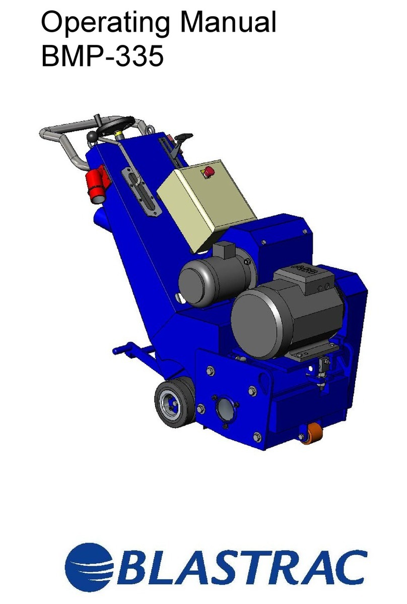
Blastrac BMP-335 EHY User manual

Original Instructions in English
OPERATING INSTRUCTIONS BMP-335 EHY/GHY
VERSION 2.4

2
Inspection comments
Recurring inspections / maintenance log
*Competent person
Date / Hour counter
Findings
Repairs / Cleaning
Test
on
By*
Inspection before initial operation on: __________________________________________
By: __________________________________________
Date of initial operation: __________________________________________
Serial number & Year of manufacture: __________________________ _____________

3
Table of contents
Maintenance log 2
1. Introduction 4
2. Machine description 4
Accessories 5
3. Safety 6
3.1 Work area safety 6
3.2 Personal safety 6
3.3 Machine safety 7
3.4 Electrical safety 7
3.5 Diesel version safety 8
3.6 Hydraulic safety 8
3.7 Dust collector safety 9
3.8 Maintenance safety 9
3.9 Transport safety 10
3.10 Signs on the machine 11
4. Initial operation 12
4.1 Checkpoints of electrical power supply 12
4.2 Checkpoints of the diesel engine 12
4.3 Checkpoints of the machine 12
4.4 Manual moving of the machine 13
4.5 Removing the drum 13
4.6 Mounting the drum 13
4.7 The scarifying drum 14
4.8 The scarifying flails and cutters 14
4.9 Control devices 15
4.10 Control devices GHY-version 17
5. Operating 19
5.1 Before starting up 19
5.2 Procedure to start work (EHY-version) 19
Procedure to start work GHY-version) 20
5.3 Operating during scarifying 21
5.4 Switch off the machine (EHY-version) 22
Switch off the machine (GHY-version) 22
5.5 Refueling the engine 25
5.6 Fuel type 25
5.7 Checking and refilling the engine oil 26
6. Maintenance 29
6.1 Maintenance of the bearings 30
6.2 The scarifying drum 30
6.3 The belt drive 31
6.4 Lubrication 32
6.5 Venting the hydraulic pump 33
6.6 Diesel engine maintenance 34
7. Troubleshooting 36
8. Technical data 38
Contact

4
1. Introduction
Before use, operators must be provided with information, instruction and training for the use of the machine
and the substances for which it is to be used, including the safe method of removal and disposal of the
material collected. All persons who are working with or maintaining this machine must read the manual
carefully and understand it fully. In case you sell the unit, hand it on to the next owner.
Keep this manual always with the machine, to enable it to be referred to at any time.
Any other work not covered by this operating manual must not be carried out. Always use common sense
when working with machines.
This machine is designed for industrial use by professionals. Only authorized and trained personnel may
operate this machine. This machine is not intended for use by persons (including children) with reduced
physical, sensory or mental capabilities, or lack of experience and knowledge. Blastrac BV offers a course on
the use of the machine in order to make the operating and maintenance personnel familiar with all elements of
the machine.
Always read the enclosed OWNER’S MANUAL of the Hatz diesel engine before operating the
machine.
The OWNER’S MANUAL contains important information about getting the best performance and safe operation
/ maintenance of the diesel engine.
The OWNER’S MANUAL should be considered a permanent part of the engine and should remain with the
engine if resold.
2. Machine description
The Blastrac scarifier BMP-335 can be supplied with a 400 volt electric motor (EHY) or with a combustion
engine (GHY). The intended use of this scarifier is to roughen up existing horizontal surfaces and removing
coatings. It can be used on almost any surface (concrete, asphalt, stone and steel). The machine may not be
used for other purposes. The manufacturer will not be liable for damage resulting from incorrect usage, in
these cases the user assumes all risks.
The drum of the scarifier revolves at +/- 1000 revolutions per minute. (RPM)
The depth of scarifying can be adjusted by the fine adjustment control at the front of the machine; by this
means it is possible to treat the surface with light or heavy cuts as is required.
The machine may not be used without an adequate dust extraction system. A specially designed Blastrac dust
collection system ensures dust-free operation of the machine and clean air at the workspace.
Application
The scarifier is a very versatile machine and with the appropriate cutters it may be used for the following
applications.
To roughen concrete
To clean most horizontal surfaces
To remove coatings
To corrugate concrete surfaces
To remove road markings
To make non-slip surfaces
The force of impact of a cutter is controlled by the depth adjustment. With the right depth adjustment, the
best performance is obtained to give a desired result.
With a suitable Blastrac dust collector work can be carried out without causing excessive dust in the work area,
this raises the life span of the machine and protects the health of the personnel.
For the GHY version (Diesel engine)
Please read the enclosed OPERATOR’S MANUAL of the diesel engine before operating the machine.
The OPERATOR’S MANUAL contains important information about getting the best performance and safe
operation of the diesel engine.
The OPERATOR’S MANUAL should be considered a permanent part of the engine and should remain with the
engine if resold.

5
Accessories
The cutters for the BMP-335 are:
MPL24 Cutter 8pt.
MPL29 Milling cutter 6pt.
MPL60-1 Milling cutter 12pt.
MPL120 Cutter 12pt.
MPL24S335-5 Refill set MPL24 cutters.
MPL29S335-5 Refill set MPL29 cutters.
MPL60S335-5 Refill set MPL60-1 cutters.
MPL120S335-5 Refill set MPL120 cutters.
MPD335-5L24S Drum complete with MPL24 cutters.
MPD335-522L29S Drum complete with MPL29 cutters.
MPD335-620L60S Drum complete with MPL60-1 cutters.
MPD335-522L120S Drum complete with MPL120 cutters.
BMP-335 EHY
BMP-335 GHY
1
Treadle of drive system
2
Dust collector connection
3
Quick lift lever
Quick lift lever
4
Handwheel working depth
5
Lifting eye
Lifting eye
6
Dead man switch
Driving lever
7
Driving lever
Air filter
8
Electrical panel
Hydraulic pump housing
9
Hydraulic pump housing
Diesel motor
10
Start cord

6
3. Safety
Warning!
Read all safety warnings and all instructions. Failure to follow the warnings and
instructions may result in electric shock, fire, explosions and / or serious injuries.
Only authorized and trained personnel may operate this machine. This machine is not intended for use by
persons (including children) with reduced physical, sensory or mental capabilities, or lack of experience and
knowledge.
It is the responsibility of the user to analyse the surface to be treated. The surface may not contain any
substances which could pose a fire-, explosion- or health risk when treated. The user should make a risk
assessment on the basis of the information obtained about the surface to be treated and take proper
precautions for the work to be performed.
In case of any inappropriate usage, improper operation or repair, the producer shall be exempt from liability.
3.1 Work area safety
a) Do not use the machine in rain, damp or wet locations.
b) Avoid dangerous environments: do not work in the presence of explosive atmospheres, in the presence of
flammable liquids, gases or dust. Remove materials or debris that may be ignited by sparks.
c) In some cases sparks could be created by scarifying or milling.
d) The surface to be treated must be clean, make sure to remove all stones, screws etc..
e) Do not use on wood.
f) Make sure there is enough ambient light on the work area. Cluttered or dark areas invite accidents.
g) Keep children and bystanders away while operating the machine. They are likely not to foresee the
potential dangers of the machine. Distractions could cause you to lose control of the machine.
h) Persons who are not operating the machine must not be permitted to stay in the surrounding area of at
least 5 meter from the machine.
i) Never use the machine when the surface is not clear and if there is a risk of stumbling or tripping.
j) Remove electrical cables and dust hose(s) from the surface to be treated.
k) Make sure that there are no cables or hoses in the driving direction of the machine.
l) Make sure that there is nothing standing or situated on the surface to be treated.
m) Make sure the machine can travel over all inequalities on the surface, small inequalities like weld seams or
(floor) joints are no barriers for the machine.
n) Never stay in the rain with the machine.
o) Check if there are any obstacles that can snag the cables when the machine is moving.
p) Remove all objects from the surface that can damage the machine. Remove reinforcing steel or other
objects protruding from the surface in order to prevent damage to the machine.
q) Warning! Make sure that the surface to be treated does not contain dangerous materials such
as: - combustible or explosive dusts or substances.
- carcinogenic or pathogenic substances.
In these cases, additional safety measures should be used. Always mind the local safety
requirements. Contact your dealer for additional options.
r) It is necessary to provide for an adequate air change rate L in the room if the exhaust air from the dust
collector is returned to the room. Comply with the National regulations.
s) Secure the work area around the machine in public areas providing an adequate safety distance from the
machine. Use a red and white safety chain and danger sign to enclose the work area.
t) Danger to life from inhaling exhaust gases. Toxic engine exhaust gases can lead to loss of consciousness
and even death in closed-off and poorly ventilated rooms.
▪ Never operate the machine in closed-off or poorly ventilated rooms.
▪ Do not breathe in the exhaust gases.
u) Only work on locations which are adequately ventilated.
3.2 Personal safety
a) Always wear Personal Protective Equipment while working with the machine.
-Dust mask class FFP3 or higher
-Ear protection
-Safety glasses with lateral protection
-Protecting gloves
-Safety shoes

7
b) Dress properly. Do not wear loose clothing or jewellery. Keep your hair, clothing and gloves away from
moving parts.
c) Personnel must tie back long hair and not wear loose clothing or jewellery including rings.
d) Stay alert, watch what you are doing and use common sense when operating the machine.
e) Always seek professional medical attention immediately in case of injury.
f) All persons surrounding the machine should wear Personal Protective Equipment.
3.3 Machine safety general
a) Safety functions and operating functions must work correct.
b) No loose bolts and nuts permitted.
c) Never operate machine without the guards and/or safety devices in place.
d) Never change anything on the safety devices on the machine!
e) Do not use the machine when it is damaged.
f) Do not open or remove protective guards while driving gears are running.
g) The temperature of the machine can be above 37° C.
h) The machine, specially the handle grips and control devices must be dry and free of fats/oils.
i) All repair work has to be done by qualified Blastrac personnel, this guarantees a safe and reliable
machine.
j) Always use original Blastrac spare parts and cutters. This will ensure the best performance.
Only original parts meet the factory specifications and quality. Otherwise Blastrac BV cannot guarantee
the safety of the machine. The part numbers can be found in the Service Manual.
k) Check the rotating direction of the motor before operation. The correct direction is given with an arrow on
the housing of the motor.
l) Make sure the drum with picks/cutters is in good condition and the picks/cutters can turn free in the
drum.
m) In some cases sparks could be created by milling / scarifying.
n) If safety-critical changes occur to the machine or its working method, the machine must be shut down
immediately! The cause of the fault must be established, and rectified.
o) In the event of operational malfunctions the machine must be shut down immediately and secured!
p) Never use the machine without a suitable (Blastrac) dust collector!
3.4 Electrical safety
a) Use only extension cables for extending the main cable that are sized and marked in accordance with the
overall power consumption of the machine. Do not use damaged extension cables.
b) Electrical cables must be rolled entirely off of the reels.
c) Any damage to the electric cables and/or electrical components is not permitted.
d) If the power supply cable or plug is damaged, it must be replaced immediately. Only use original Blastrac
parts.
e) The voltage on the identification plate must comply with the power supply.
f) Use an electrical power supply connection with earth connection and earth leakage circuit breaker.
g) The circuit breaker of the power supply must have a ‘’D’’ characteristic. Circuit breakers with a “C” or “B”
characteristic can give problems when switching the machine on.
h) Keep the machine original; The machine is always equipped with an earthed connection, do not
change this and always use earthed cables with an earthed plug.
i) Inspect and test the electrical components regularly. The electrical components have to satisfy with the
requirements set out in the harmonised norm EN60204-1.
j) Always call a skilled electrician or your distributor when you have questions about the safety of the
electrical components.
k) Work on electrical equipment or operating materials may only be undertaken by a skilled electrician or by
trained persons under the guidance and supervision of a skilled electrician as well as in accordance with
the electrical engineering regulations.
l) Always use tools that are insulated against voltages.
m) Do not abuse the cables. Never use the cables for carrying, pulling or unplugging the machine. Keep
cables away from heat, oil, sharp edges or moving parts. Damaged or entangled cables increase the risk
of electric shock. Do not fold the cable or clamp it.
n) Don’t pull out the power supply cable out by the wire, but by the connector.
o) o) Be careful with water on the treated surface. Electrical cables must not come into contact with water.
p) During a long standstill of the machine, pull out the main plug.
q) If the machine is to be operated using power from a generator, the generator must be operated in
accordance with the current legal regulations and directives in force. (this applies to the protective earth
conductor in particular) in order to ensure that all safety devices are functioning and to eliminate possible
damage to electrical components.

8
3.5 Diesel version safety
a) Read the enclosed Operating Instructions of the diesel engine before using it.
b) Make sure there is no oil or diesel leaking out of the diesel engine.
c) Always make a pre-operation inspection before you start the engine. You may prevent an accident or
equipment damage.
d) Look for signs of damage and remove any excessive dirt or debris.
e) To prevent fire hazards and to provide adequate ventilation, keep the engine at least 1 meter
(3 feet) away from buildings and other equipment during operation.
Do not place flammable objects close to the engine.
f) Anyone who is not operating this machine must be kept away from the area of operation due to a
possibility of burns from hot engine components. Parts will remain hot for a while after stopping the
engine. Let the engine cool before transporting it or storing it indoors.
g) When transporting or storing the engine, turn the fuel valve OFF and keep the engine horizontal.
h) Know how to stop the engine quickly, and understand the operation of all controls. Never permit anyone
to operate the engine without proper instructions.
i) Do not place flammable objects such as gasoline, matches, etc., close to the engine while it is running. Do
not place anything on the engine.
j) Refuel in a well-ventilated area with the engine turned OFF. Gasoline / diesel is highly flammable and
explosive under certain conditions. Let the engine cool before refueling.
k) Do not overfill the fuel tank. There should be no fuel in the filler neck.
l) Do not smoke or allow flames or sparks where the engine is refueled or where gasoline / diesel is stored.
m) ! Exhaust gas contains poisonous carbon monoxide ! Avoid inhalation of exhaust gases. Never run
the engine in a closed garage or confined area! Always wear a dust mask.
Breathing carbon monoxide can cause unconsciousness or death.
n) If any fuel is spilled, clean it up completely and allow petroleum vapours to dissipate before starting the
engine.
o) Make sure the fuel and oil level are correct and that the filler cap is closed securely.
p) Don’t leave the machine laying backwards for a long time, because this may result in fuel spillage.
q) Comply with all notices and warning labels on the engine and keep them in a legible condition. If a label
should become detached or difficult to read, it must be replaced promptly. For this purpose, contact your
nearest HATZ service station.
r) Any improper modification of the engine will result in a loss of liability coverage for resulting damage.
s) Only regular maintenance, as specified in the Hatz manual, will maintain the operating readiness of the
engine.
t) Disconnect the negative battery terminal before carrying out maintenance work.
3.6 Hydraulic safety
a) Make sure all hydraulic hose connections are tightened and there is no leakage of oil.
b) Over tightening could damage O-rings. If a leak still persists, remove fitting and replace O-ring.
c) Make sure the hydraulic hoses have no damages, signs of wear or other defects.
d) Hydraulic fluid under pressure is dangerous and can cause serious injury.
e) Never look for a leak when the unit is under pressure.
f) Avoid leaks by keeping fittings and hoses tight, only check and service when not under pressure.
g) Leaking hydraulic fluid is not only unsightly, it’s dangerous. It could make workplace floors slippery,
contaminate the environment and could create a possible fire/explosion hazard.
h) Never change the oil pressure of the machine! Changing the oil pressure could cause serious damage to
the machine and could result in very dangerous situations!
i) Only work with the hydraulic oil in an area that is well-ventilated, otherwise you must wear suitable
respiratory protection. Always wear Personal Protective Equipment when handling the oil:
-Protecting gloves (preferably made of nitrile or neoprene.)
-Safety goggles.
-Hydrocarbon-proof clothing and safety shoes.
j) Avoid long and repeated contact with the skin, after contact wash thoroughly with water and soap.
Contact with eyes: Immediately flush eyes with cold, fresh water for a minimum of 15 minutes. Seek
professional medical attention.
k) Do not eat, drink or smoke near the hydraulic oil.
l) HV46 hydraulic oil holds no danger of intoxication.
m) The hydraulic oil is stable at normal temperatures for storage, handling and use. However, the hydraulic
oil is flammable when exposed to certain conditions. Empty containers may contain flammable or
explosive vapors. Rags that are soaked with the product and paper or materials which have been used for
absorbing the spilled product are inflammable. Make sure that no accumulation occurs. Remove safely
after use.
n) Avoid sparks, open flames, extremely high temperatures and other sources of ignition.
o) Please read the Safety Data Sheets for additional information regarding the hydraulic oil.

9
p) Only use HV46 hydraulic oil (E00481), non-compatible fluids could cause damage to the unit or serious
injury.
q) At least one time during year oil from system and the filter should be replaced.
r) Work on hydraulic equipment or operating materials may only be undertaken by a skilled hydraulic
engineer or by trained persons under the guidance and supervision of a skilled hydraulic engineer as well
as in accordance with the hydraulic engineering regulations.
s) Hoses and pipe work can be under high (hydraulic) pressure. The temperature can be above 37° C. Use
only hoses and pipe work that are sized and marked in accordance with the overall power consumption of
the machine.
t) A second person must be deployed who can disengage the hydraulics in an emergency if work on live
parts is necessary. The work area must sealed off using a red and white safety chain and a danger sign.
For the electrical parts, use a tool that is insulated against voltages.
3.7 Dust collector safety by a machine
a) Always use a Blastrac dust collector to ensure a dust-free operation of the machine and clean air at the
workspace. Also the airflow helps to cool the machine and prevents overheating.
b) Read the operating instructions of the dust collector before using it.
c) The dust container/bag of the dust collector must be emptied regularly. Comply with the local waste
treatment regulations considering the removed material.
d) The dust hose must be connected properly with a hose clamp and industrial tape.
e) The dust hose must be undamaged and free of obstructions.
f) Always switch on the dust collector first!
3.8 Maintenance safety
a) Pull out the main plug and place it in sight, before changing the drum or starting inspections and repairing
on the machine. Pull out the key of the dead man’s switch and keep it in your pocket.
b) Wait for a standstill of all drives before any inspections, adjustments and/or maintenance work is started.
c) Block the machine in a stable position before doing any maintenance work.
d) Failures due to inadequate or incorrect maintenance may generate very high repair costs and long
standstill periods of the machine. Regular maintenance therefore is imperative.
e) Operational safety and service life of the machine depends, among other things, on proper maintenance.
f) Prevent premature wear by keeping the machine as dust free as possible. Clean the machine for this
reason regularly with a dust collector and non-aggressive materials. Never use a high pressure water
cleaner to clean the machine.
g) Do not use any aggressive cleaning materials!
h) Use lint-free cleaning cloths!
i) Please advise the OWNER’S MANUAL of the diesel engine for additional information.
j) It is advisable to stock all spare parts or wear parts that cannot be supplied quickly. As a rule, production
standstill periods are more expensive than the cost for the corresponding spare part.
k) The suitable precautions include decontamination before disassembling the machine, adequate filtered
ventilation of the exhaust air from the room in which it is disassembled, cleaning of the maintenance area
and suitable personal protection equipment.
l) Always read the enclosed OWNER’S MANUAL of the Hatz diesel engine before operating the machine.
m) The OWNER’S MANUAL contains important information about getting the best performance and safe
operation / maintenance of the diesel engine.
n) The OWNER’S MANUAL should be considered a permanent part of the engine and should remain with the
engine if resold.

10
3.9 Transport safety
a) Be aware of your surroundings and machine operating level. Do not side hill, do not run on steep incline,
this could cause machine to tip over.
b) The weight of the BMP-335 EHY is 405 kg, the BMP-335 GHY is 370 kg. Use a crane or lift when
transporting the machine, use the lifting eyes on the machine.
c) Before every use check the lifting eyes and welds for: deformation, damages, cracks, corrosion and wear.
d) When lifting the machine from the ground, always use the lowest lifting speed. The cables must first be
tensioned at this speed; they must not be slack when the machine is lifted from the ground.
e) During hoisting make sure to be at a safe distance from the machine with the most optimal view on the
machine and working environment.
f) Never stand directly below the machine.
g) When transporting the machine do so in such a manner that damage due to the effects of the use of force
or incorrect loading and unloading is avoided.
h) The lifting eyes can also be used to fasten the machine on a pallet or during transport.
i) Always drive backwards when driving up to a ramp or grade, and forwards when driving of the ramp.
j) Chock wheels for transport and keep the treadle in engaged position, this will function as a brake on the
wheels.
k) Don’t leave the machine unsecured on jobsites.
l) Park the machine always on a flat horizontal and levelled surface.
m) Remove the dirt, dust and debris from the machine before transport.
n) Make sure the electrical cable and dust hose are disconnected before transport.
o) Store the cleaned and dry machine in a humid free room. Protect the motor from moisture, heat dust and
shocks.
p) Never use the machine for lifting persons or items.
q) It is possible to transport the machine without the use of the motor by pushing up the treadle (pos. 1,
page 5). The drive wheels are declutched of the drive motors now. Make sure that the floor is flat,
because the machine is uncontrolled now! It is very dangerous to drive the machine on a grade or
ramp when the treadle is in upwards position! Never load or unload the machine on a ramp or
incline when the wheels are in the disengage mode. Failure to do so could cause machine to runaway,
damage to the machine, damage to property or cause serious injury.
r) Only lift the machine as shown in the picture below. Use the existing lifting points to lift the machine.

11
3.10 Signs on the machine
The following stickers are placed on the machine. Meanings of these symbols are:
Type plate:
EU Declaration of Conformity:
! Danger Hazardous voltage in motor
even when solid state controller is OFF.
Disconnect main power before servicing
motor, controller or associated wiring.
Warning! Hot surface.
DANGER Rotating parts inside.
Keep hands clear.
Lock-out / shut down before servicing.
Wear a dust mask class FFP3
or higher.
Hearing protection is obliged.
Safety glasses with lateral
protection are obliged.
CE-mark on this machine.
Wear protecting gloves.
Safety shoes obliged.
Consult the manual before
operating the machine.
Name, address and CE mark.
The machine type.
The net weight of the machine in kilogram.
The year of manufacture.
The serial number of the machine.
Email address, Website, Telephone & fax number.

12
4. Initial operation
Before using the machine it is of great importance to inspect the machine.
It is not permitted to use the machine if the machine safety is not according the checkpoints below.
4.1 Checkpoints electrical power supply (EHY-version)
Use only extension cables for extending the main cable that are sized and marked in accordance with
the overall power consumption of the machine.
Electrical cables must be fully unwind of their reels.
No damage is permitted for electrical cables.
Use an electrical power supply connection with earth connecting.
Make sure the power supply is in accordance with the machine specifications.
The circuit breaker of the power supply must have a ‘’D’’ characteristic. Circuit breakers with a “C” or
“B” characteristic can give problems when switching the machine on.
If the machine is to be operated using power from a generator, the generator must be operated in
accordance with the current legal regulations and directives in force. (this applies to the protective
earth conductor in particular) in order to ensure that all safety devices are functioning and to eliminate
possible damage to electrical components.
4.2 Checkpoints of the diesel engine (GHY-version)
Make sure the location is adequately ventilated.
Make sure there is a sufficient amount of fuel in the fuel tank.
Make sure there is a sufficient amount of engine oil in the engine.
Make sure no persons are located in the danger zone of the engine or machine.
All safety equipment is in place.
4.3 Checkpoints of machine
Safety functions and operating functions must work correct.
Check all screws and other fasteners for tightness. No loose bolts and/or nuts are permitted.
Check the electrical components, cables and connections for wear and/or damages.
Check the hydraulic components on the machine for damages and wear.
Dust hose connections must be reliable: use hose clamps and industrial tape.
Dust hose must be undamaged and free of obstructions.
Check the tension of the belt after a drum is placed in the machine.
Make sure the drum is in good condition.
Make sure the drum is assembled as shown in the service manual.
Check, when using non symmetric cutters, if the direction of turning is like the figure below.
The tools must hit the floor by centripetal force and not because the axle pushes the tool
(see drawing below).

13
4.4 Manual moving of the machine
To move the machine manually push the treadle up with your foot. The wheels are now disengaged from the
drive motors. The machine can now be pushed around on its wheels.
Make sure that the floor is flat, because the machine is uncontrolled now! It is very dangerous to drive the
machine on a grade or ramp when the treadle is in upwards position! Never load or unload the
machine on a ramp or incline when the wheels are in the disengage mode. Failure to do so could cause
machine to runaway, damage to the machine, damage to property or cause serious injury.
Push the treadle down when parking the machine, engaging the wheels to the drive system will act like a
parking brake when the machine is turned off.
The machine should only be moved around when the dust hose, and power supply cable are disconnected.
WARNING! Always make sure all rotating parts have come to a complete standstill before moving around the
machine.
Be careful! Make sure nobodies feet get under the wheels. Wear appropriate safety shoes when you drive the
machine to or from the work area.
Make sure that no vehicles, such as forklift trucks and other equipment run over the electric cable and the dust
hose.
4.5 Removing the drum
Make sure all moving parts of the machine have come to a
complete standstill before changing the drum. Pull out the key
of the deadman’s switch and put it in your pocket.
Warning!
Always wear Personal Protective Equipment!
The dust can be hazardous to the health!
Wear a dust mask! Wear protective gloves!
1. Loosen the 4 bolts of the side plate
2. Remove the side plate (2)
3. Pull the drum from the axle, and support the drum.
4.6 Mounting the drum
Clean the hexagon axle inside the machine and lubricate it over the whole length.
Slide the drum over the axle until it will not go any further.
Mount the side plate. A side plate which is incorrectly mounted or mounted with force, will shorten the
lifetime of the drum bearings.
Always check the belt tension after mounting a drum (see chapter 6.2).
Never use the machine without a side plate or with an incorrect mounted side plate!

14
4.7 The scarifying drum
The heart of the scarifier is the scarifying drum. The assembly of the scarifying drum is very easy. Each tool
will be pushed on the axle together with spacers according to the enclosed assembly plans (Service manual).
The spacers ensure the necessary distance between the flails or cutters. The enclosed assembly plans take into
account the required lateral clearance of the flails or cutters, approximately 3 - 5 mm.
4.8 The scarifying flails and cutters
Through the use of different flails or cutters, and with a few alterations, it
is possible to adjust the Blastrac scarifier for the applications or rather for
the requirements of the specific surfaces. All the machines work according
to the principle of a loose tool seated on an axle. The rotation of the
scarifying drum generates a centrifugal force on the flails or cutters which
are kept by the lateral axles. The flails will be thrown outwards as far as
the clearance between flail and axle allow it. When striking the surface,
particles will be taken off of the surface and the flail will rebound in the
maximum inner position. So to avoid significant wear on the axles as well
as on the drum, it is required that the flails still have enough clearance on
the axle when striking the surface.
1
Safety screw
2
Spring lock washer
3
Lock plate
4
Pin
5
Scarifying drum
6
Axle
7
Distance ring
8
Scarifying flail or cutter
The tools must hit the floor by
centripetal force and not because
the axle pushes the tool
(see drawing below).
MPD335-522L24S
DRUM COMPLETE
WITH MPL24 CUTTERS
MPD335-522L29S
DRUM COMPLETE
WITH MPL29 CUTTERS
MPD335-620L60S
DRUM COMPLETE
WITH MPL60-1
CUTTERS
MPD335-522L120S
DRUM COMPLETE
WITH MPL120 CUTTERS

15
4.9 Control devices
1. Treadle of drive system
It is possible to transport the machine without the use of the motor by pushing up the treadle (1). The
drive wheels are declutched of the drive motors now. In the downward position the wheels are
engaged to the drive motors. Make sure that the floor is flat, because the machine is uncontrolled now!
It is very dangerous to drive the machine on a grade or ramp when the treadle is in upwards
position!
2. Dust hose connection
The dust hose to the dust collector must be connected here. Use hose clamps and industrial tape for a
reliable connection.
3. Quick lift lever
In the upright position the drum is lifted off of the ground, in the downwards position, the drum is put
on the ground. The quick lift lever enables the operator to lift the complete drum without changing the
fine adjustment of the working depth. The lever must be in the upright position before start-up, in
order to prevent a run out of the motor under full load.
4. Fine adjustment
The working depth can be adjusted by turning the fine adjustment wheel. The scarifying depth must be
adjusted considering the surface to be treated. The progressively depth adjustment enables the flails
or cutters to impact on the surface being treated only at the required and necessary depth. The flails or
cutters must be unhindered thrown up through the centrifugal force and they must turn free over the
BMP-335 EHY
1
Treadle of drive system
2
Dust collector connection
3
Quick lift lever
4
Handwheel working depth
5
Lifting eye
6
Dead man switch
7
Driving lever
8
Electrical panel
9
Hydraulic pump housing
10
11
Emergency shutdown button
12
“Hydraulic motor” ON/OFF buttons
13
Control light “Phase incorrect”
14
“Scarify motor” ON/OFF buttons
16
Plug for power supply
16

16
lateral axle. When the depth adjustment is correctly selected, the scarifier will run quiet and constant.
Oval worn flails or cutters as well as broken drum axles indicate a too "high" scarifying depth
adjustment.
6. Dead man’s switch
The key of the dead man’s switch is attached to a cord. The cord should be fastened on the arm of the
operator. When the key is pulled out, the machine will stop immediately.
7. Driving lever
The drive unit control lever is used to control the machine’s drive unit. The function of the drive unit
control lever begins after adjusting the working depth of the machine with the quick lift. You should
pay attention that the drive unit control lever is locked in the neutral position before manipulating the
quick lift.
11. Emergency shutdown button
Red mushroom-shaped shutdown push button, this button cuts off the power to the motors.
Turn to unlock the emergency stop button.
12. Hydraulic motor ON/OFF buttons
Pressing the green start button will start the driving motor, use the driving lever to start driving. The
hydraulic motor hast to be switched on before switching on the scarify motor. The red button will stop
the hydraulic motor.
13. Control light “Phase incorrect”
This lamp shines when the phases of the power supply are incorrect. The power plug has a built in
phase inverter for easy and quick changing of the phases if the control light “Phase incorrect” lights up.
14. “Scarify motor” ON/OFF buttons
Pressing the green start button will start the scarify motor. Before starting the scarify motor, the
treadle of the drive system must be in de downwards position and the quick lift lever must be in the
upwards position.
16. Plug for power supply
The plug for the power supply has a built in phase inverter.
If the motor turns the wrong way, just unplug the machine and change the phase inside the plug.

17
4.10 Control device BMP-335 GHY
Photo 1.
BMC-335 GHY
1
Treadle of drive system
2
Dust collector connection
3
Quick lift lever
4
Handwheel working depth
5
Lifting eye
6
Driving lever
7
Air filter
8
Hydraulic pump housing
9
Diesel motor
10
Ignition lock
11
Speed control lever
O
Position 0
I
Position I
II
Position II
A
Engine temperature display
B
Oil pressure display
C
Charge control
D
Operating display
E
Earth switch

18
1Treadle of drive system
It is possible to transport the machine without the use of the motor by pushing up the treadle (1). The
drive wheels are declutched of the drive motors now. In the downward position the wheels are
engaged to the drive motors. Make sure that the floor is flat, because the machine is uncontrolled now!
It is very dangerous to drive the machine on a grade or ramp when the treadle is in upwards
position!
2Dust hose connection
The dust hose to the dust collector must be connected here. Use hose clamps and industrial tape for a
reliable connection.
3Quick lift lever
In the upright position the drum is lifted off of the ground, in the downwards position, the drum is put
on the ground. The quick lift lever enables the operator to lift the complete drum without changing the
fine adjustment of the working depth. The lever must be in the upright position before start-up, in
order to prevent a run out of the motor under full load.
4Fine adjustment
The working depth can be adjusted by turning the fine adjustment wheel. The sawing depth must be
adjusted considering the surface to be treated. The progressively depth adjustment enables the sawing
blades to saw into the surface being treated only at the required and necessary depth. When the depth
adjustment is correctly selected, the machine will run quiet and constant.
6Driving lever
The drive unit control lever is used to control the machine’s drive unit. The function of the drive unit
control lever begins after adjusting the working depth of the machine with the quick lift. You should
pay attention that the drive unit control lever is locked in the neutral position before manipulating the
quick lift.
10 Ignition lock
The ignition lock is used to start the BMC 335 GHY electrical.
11 Speed control lever
With the speed control lever you can change the speed of the diesel engine. The speed control lever is
also used to shut down the engine.
A Engine temperature display
If the engine temperature display lights up, the cylinder head temperature is too high. Do not start the
engine. If the engine is running, switch off the engine immediately! Danger of engine damage.
B Oil pressure display
If the oil pressure display lights up, switch off the engine immediately! Danger of engine damage.
C Charge control
If the charge control lights up during operation, there is a fault in the alternator. In position (I) the
display lights up, but after starting the engine it will go out.
D Operating display
Lights up during operation when there is no engine fault.
E Earth switch
Disconnects the batteries from the system.

19
5. Operating
During operating the BMP-335, the following additional safety instructions must be followed closely.
Before switching on the machine make sure that no-one can be endangered when the machine starts up.
5.1 Before starting up
Make sure that the drum doesn’t hit the ground. The quick lift lever must be in upper position and the
fine adjustment must be turned up.
Connect the scarifier and the dust collector with the dust hose. Make sure there is a good and airtight
connection, use hose clamps and industrial tape.
Connect the scarifier and the dust collector with the power supply. Make sure the right connection is
available for the machines. (only BMP-335EHY)
5.2 Procedure to start work (EHY version)
Turn the dust collector on.
Put the cord of the dead man switch around the left wrist.
Start the machine by pushing the buttons ‘hydraulic motor ON’ and ‘scarify motor ON’ (BMP-335EHY)
or by pulling the start cord of the diesel motor. (BMP-335GHY)
Check if the drum turns the right direction. (Only BMP-335EHY)
Slowly let down the quick lift lever.
Turn the fine adjustment clockwise until the desired scarifying depth is reached.
Push the driving lever a little bit forward to make the machine go forward.
All persons in the proximity of the machine must wear safety glasses with lateral
protection as well as safety shoes and ear protection. The operator is obliged to wear
close-fitting protective clothing and a dust mask.

20
Procedure to start work (GHY version)
Turn on the dust collector
Check if the treadle of the drive system is down, and the driving lever is in the neutral position.
Turn the earth switch into a vertical position. See photos 2.1.
Turn the starting key to position "0", every time you want to start the engine. (See photo 2.2).
Check the throttle lever, first move the throttle lever to the stop position. (see photo 2.3)
Depending on the situation, place the throttle lever in either the "½" or "start" position.( see photo 3
and 4).
Photo 3. "½" position Photo 4. "start" position.
Insert the starting key all the way and turn to position (I). (see photo2.2)
Turn the key to position (II). (see photo 2.2). As soon as the engine is running, release the starting
key. The starting key springs back into position "I" and remains in this position during operation.
Slowly let down the quick lift lever.
Turn the fine adjustment clockwise until the desired depth is reached.
Push the driving lever forward to drive the machine forwards. This must be done once the machine is
on the floor.
Photo 2.1
Photo 2.2
Photo 2.3
This manual suits for next models
1
Table of contents
Other Blastrac Lawn And Garden Equipment manuals
Popular Lawn And Garden Equipment manuals by other brands

Stratco
Stratco Handi-Mate HMGSHM3AZ installation guide

Meec tools
Meec tools 001-445 operating instructions

DynaTrap
DynaTrap DT1050-TUN owner's manual

Echo
Echo HC-185 Operator's manual

PICOTE
PICOTE MINI MILLER 8/16 Operation & safety manual

The ORGANIC GARDEN Co
The ORGANIC GARDEN Co OGC200100RX quick start guide