BLAUBERG VENTO Solar V60 Pro User manual

VENTO Solar V60 Pro
HEAT RECOVERY SINGLE-ROOM
VENTILATION UNIT
OPERATION MANUAL
EN
VENTO_Solar_V60_Pro_v.1(2)_EN.indd 1 07.08.2015 12:06:35

2
www.blaubergventilatoren.de
VENTO Solar V60 Pro
CONTENTS
Introduction 3
General 3
Safety rules 3
Transportation and storage rules 3
Manufacturer's warranty 3
Design and operating logic 4
Modications and options 5
Delivery set 5
Technical data 6
Mounting 7
Connection to power mains and control 10
Maintenance 15
Troubleshooting and fault handling 16
Acceptance certicate 17
Connection certicate 17
Warranty card 17
VENTO_Solar_V60_Pro_v.1(2)_EN.indd 2 07.08.2015 12:06:36

www.blaubergventilatoren.de
3
VENTO Solar V60 Pro
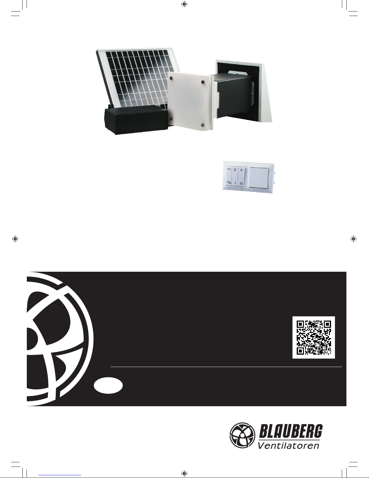
BLAUBERG Company is happy to oer your attention a new heat recovery
single-room unit VENTO Solar V60 Pro / VENTO Solar V60 Pro2.
INTRODUCTION
The present operation manual contains a technical description, technical
data sheets, operation and mounting guidelines, safety precautions and
warnings for safe and correct operation of the unit.
GENERAL
The single-room unit is designed for ecient energy saving supply and
exhaust ventilation of ats, houses, cottages and other small premises.
The heat recovery technology is used to minimize ventilation heat losses.
The unit is powered by the solar energy generated by a solar panel. In
case of a long-continued the unit changes into electric power supply mode.
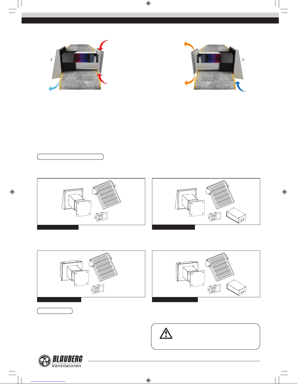
The unit is equipped with a high-tech ceramic energy regenerator that
provides extract air heat recovery for warming up of ltered supply air. The
heat recovery eciency of the energy regenerator is up to 88%.
The unit is designed for indoor application with the ambient temperature
ranging from -20 °C up to +50 °C and relative humidity up to 80%.
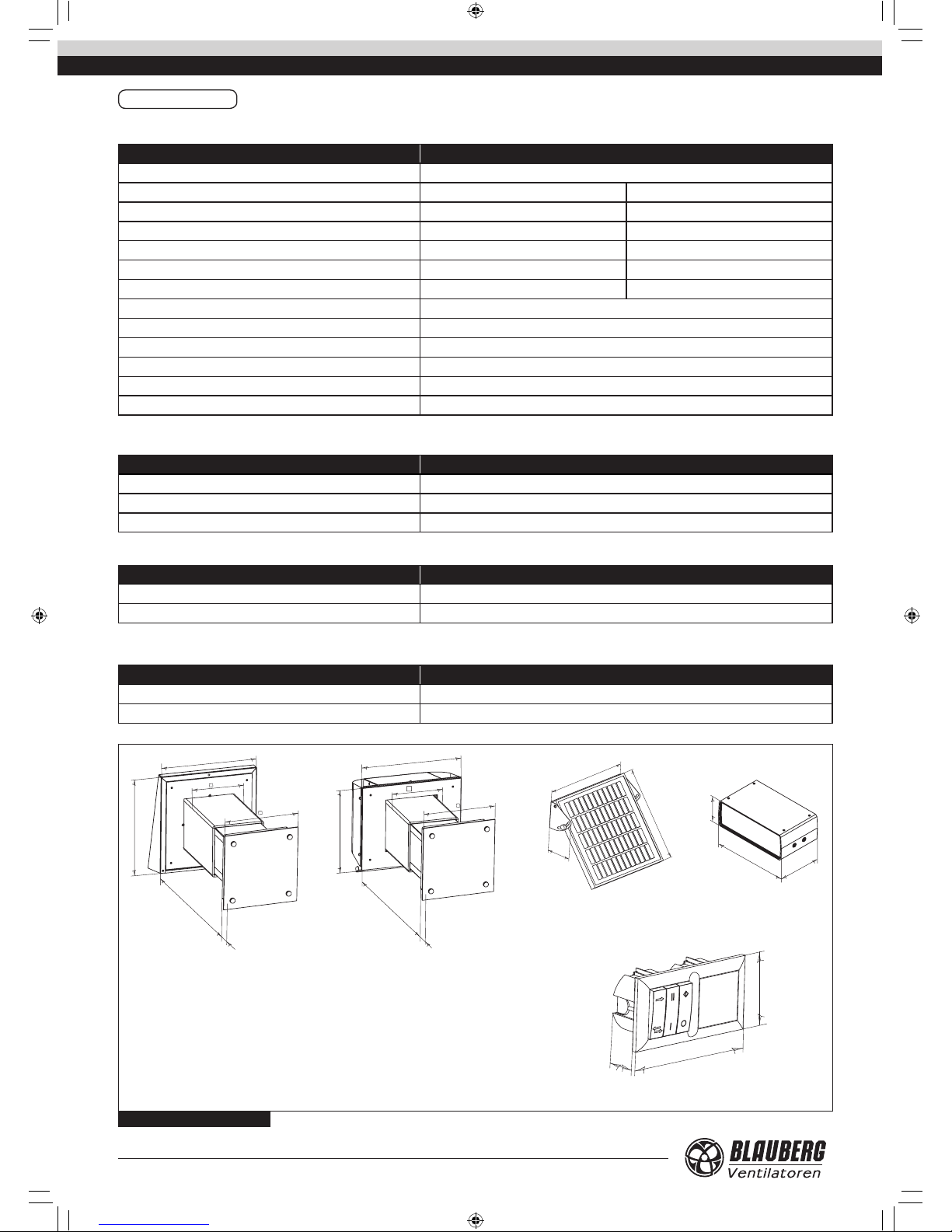
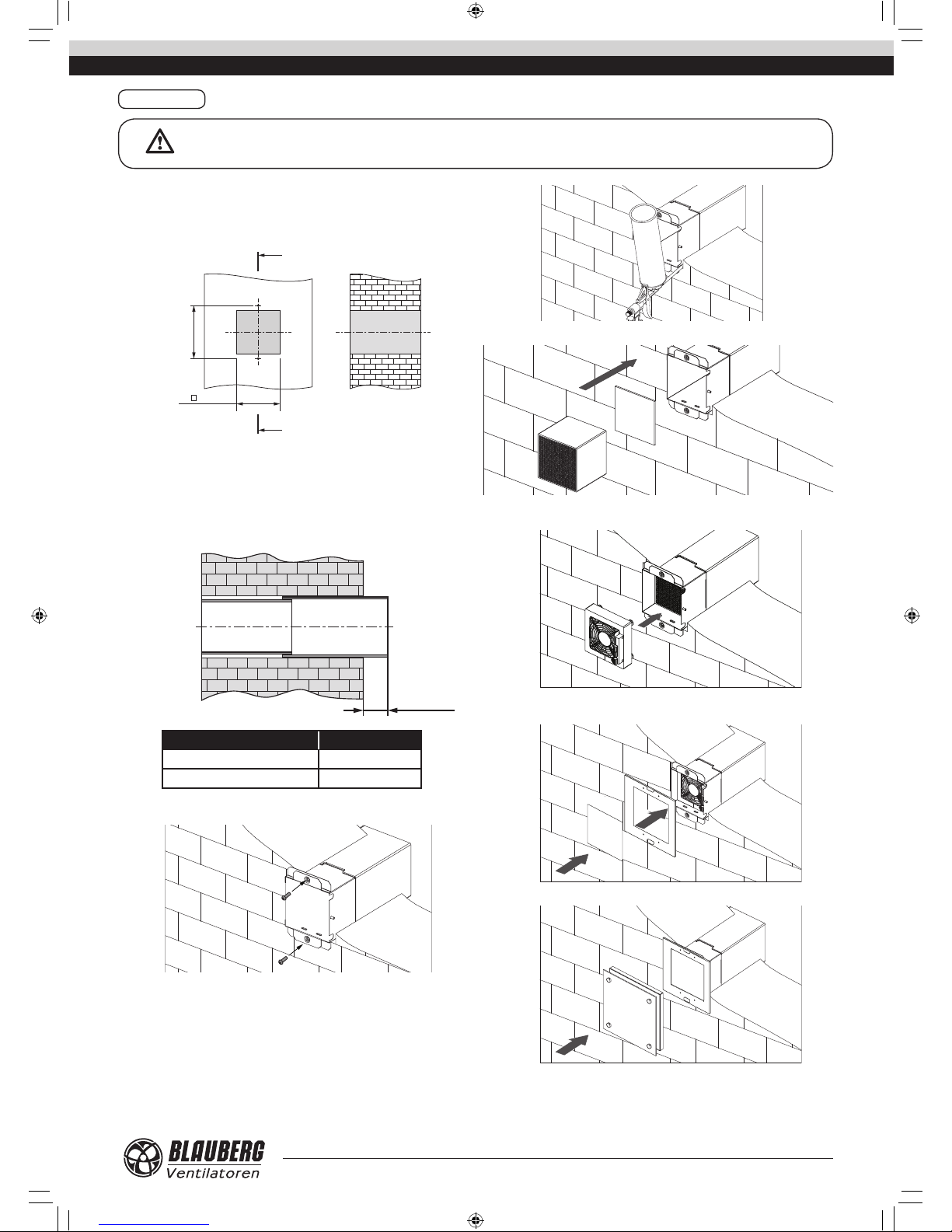
The unit is designed for external through-the-wall installation. The unit is
designed for continuous operation always connected to power mains.
The unit is allowed for operation only after nal mounting that includes
installation of protecting devices in compliance with DIN EN ISO 13875 (DIN
EN ISO 12100) as well as other construction safety equipment.
The unit design is regularly improved, so some models may slightly dier
from those ones described in this operation manual.
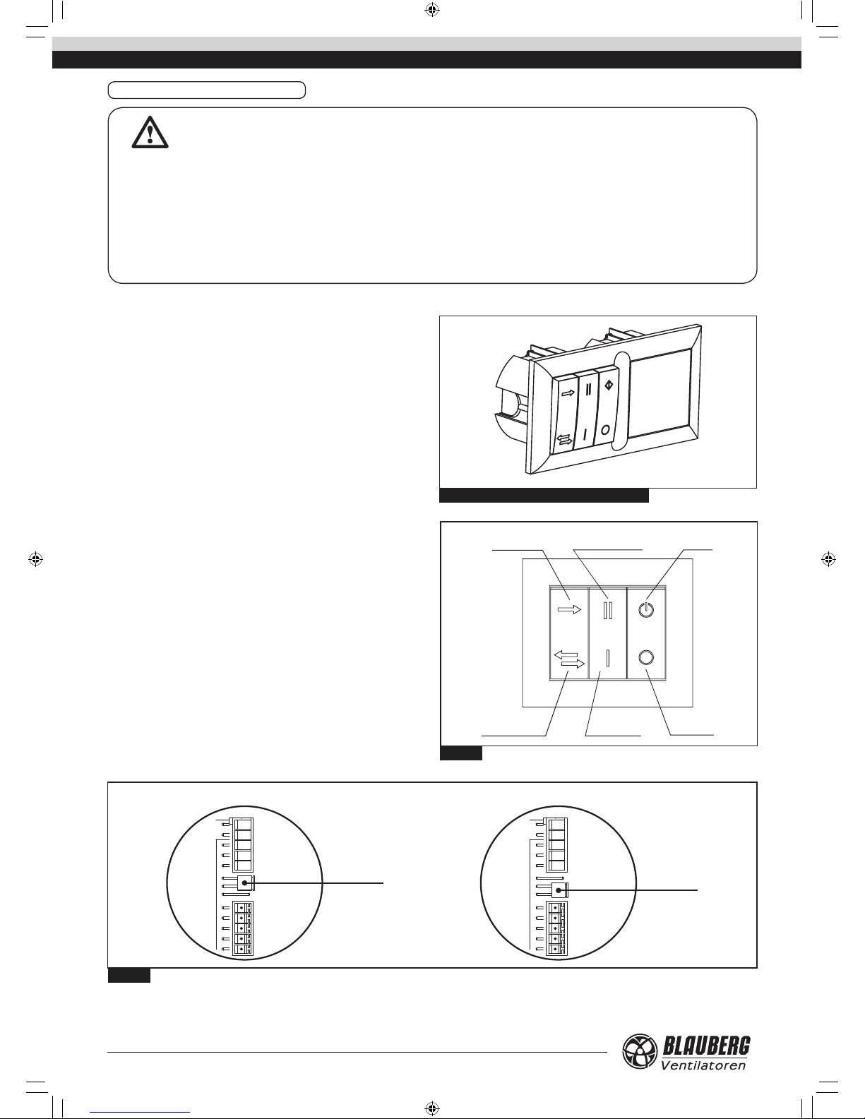
SAFETY RULES
All operations related to the unit electrical connections, servicing and
repair works are allowed only after the unit disconnection from power mains.
All mounting and servicing operations are allowed for duly qualied
electricians with valid electrical work permit for electric operations at the
units up to 1000 V after careful study of the present operation manual.
The unit is rated as a Class I electrical appliance.
Please follow the safety regulations and working instructions (DIN EN 50
110, IEC 364).
Make sure the impeller and the casing are not damaged before
connecting the unit to power mains. The casing internals must be free of any
foreign objects which can damage the impeller blades.
Disconnect the unit from power mains prior to any operations related to
the unit servicing and repair works. Make sure the rotating parts have come
to a full stop.
Misuse of the product or any unauthorized modication are not allowed.
The unit is designed for connection to AC single-phase power mains, see
«Technical Data». The unit is rated for permanent operation during non-stop
power supply.
Take steps to prevent ingress of smoke, carbon monoxide and other
combustion products into the room through open chimney ues or other
re-protection devices. Sucient air supply must be provided for proper
combustion and exhaust of gases through the chimney of fuel burning
equipment to prevent back drafting. The maximum permitted pressure
dierence per living units is 4 Pa.
The transported air must not contain any dust or other solid impurities,
sticky substances or brous materials.
The unit is not designed for use in an inammable and explosive medium.
Do not close or block the unit intake or exhaust vent not to disturb the
normal air passage.
Do not sit on the unit and do not put objects on the unit.
In case of unusual sounds, smoke disconnect the unit from power supply
and contact the service centre.
Follow the operation manual guidelines to ensure trouble-free operation
and long service life of the unit.
Hazardous parts access and water ingress protection standard IP24.
TRANSPORTATION AND STORAGE RULES
Transportation of the unit is allowed by any vehicle provided the unit is
transported in the original package and is protected against weather and
mechanical damages.
Use hoist machinery for handling and transportation to prevent possible
mechanical damages of the unit. Full the requirements for transportation of
the specied cargo type during cargo-handling operations.
Store the unit in a dry and cool place in the original packing.
The storage environment must not be subjected to any aggressive and/
or chemical evaporations, admixtures, foreign objects that may provoke
corrosion and damage connection tightness.
Store the unit in an environment with minimized risk of mechanical
damages, temperature and humidity uctuations.
Do not expose the unit to the temperatures below +10 °C and above +40
°C .
Connection of the unit to power mains is allowed after the unit has been
kept indoor for minimum two hours.
MANUFACTURER’S WARRANTY
The product complies with the requirements according to the EU norms
and directives, to the relevant EU-Low Voltage Equipment Directives, EU-
Directives on Electromagnetic Compatibility.
We hereby declare that the following product complies with the essential
protection requirements of Electromagnetic Council Directive 2004/108/
EC, 89/336/EEC and Low Voltage Directive 2006/95/EC, 73/23/EEC and
CE-marking Directive 93/68/EEC on the approximation of the laws of the
Member States relating to electromagnetic compatibility.
The manufacturer hereby warrants normal operation of the product over
the period of 2 years from the retail sale date provided observance of the
installation and operation regulations.
In case of failure due to manufacturing fault during the warranty period
the consumer has the right for a replacement unit.
If case of no conrmation of the sale date, the warranty period shall be
calculated from the manufacturing date.
The replacement is oered by the Seller.
The manufacturer shall not be liable for any damage resulting from any
misuse of or gross mechanical interference with the unit.
Full the operation manual requirements to ensure a trouble-free and
long service life of the unit.
WARNING
Do not dispose in domestic waste.
The unit contains in part material that can be
recycled and in part substances that should not end up
as domestic waste.
Dispose of the unit once it has reached the end of
its working life according to the regulations valid where
you are.
ATTENTION
The product is not allowed for use by children and persons
with reduced physical, mental or sensory capacities, without proper practi-
cal experience or expertise, unless they are controlled or instructed on the
product operation by the person(s) responsible for their safety. Supervise
the children and do not let them play with the product.
VENTO_Solar_V60_Pro_v.1(2)_EN.indd 3 07.08.2015 12:06:36

4
www.blaubergventilatoren.de
VENTO Solar V60 Pro
DESIGN AND OPERATING LOGIC
The unit consists of a decorative front panel, a telescopic air duct with
adjustable length, a ventilation unit, an energy regenerator, an outer
ventilation hood, a solar panel and a control panel with a power unit.
The inner part of the telescopic air duct encloses a ventilation unit, a
ceramic energy regenerator and a lter. The square telescopic air duct is
made of polymer coated metal and is lined with insulation material. The duct
length is adjustable and depends on the model:
– 255 up to 475 for VENTO Solar V60 Pro / V60 Pro2;
– 120 up to 430 mm for VENTO Solar V60 S Pro / V60 S Pro2.
The unit is equipped with a high-tech ceramic energy regenerator with
heat recovery eciency up to 88%. Due to its cellular structure the energy
regenerator has a large heat exchange surface and a high eciency. The
energy regenerator is featured with high heat insulating and accumulating
properties. The regenerator recovers extract air heat energy for warming up
of supply air ow. A pull cord inside of the energy regenerator facilitates its
withdrawal. The energy regenerator rests on an insulating material used as
sealer as well.
A decorative front panel with a lter is to be installed on inner wall.
Air is supplied and extracted with an axial reversible EC-fan with low
energy demand. The motor has overheating protection and ball bearings for
a longer service life.
Two built-in lters with total lter class G3 are used for supply and extract
air ltration and prevent contamination of the energy regenerator.
The outer ventilation hood must be installed on outer side of the building
to prevent ingress of large objects and water into the unit.
The integrated control system enables two-speed operation o at
minimum or maximum speed:
operation in ventilation mode (air supply or air extract);
operation in reversible mode with heat regeneration.
The unit is operated with the external power and control unit SEV-T12
(included in the delivery set).
The VENTO Solar V60 Pro2 delivery set includes a storage battery with a
charger that accumulates solar energy to enable standby operation of the
unit in the night time.
8
9
10
11
1
2
3
4
5
6
7
12
2
Fig. 1. Unit design
1. Decorative front panel.
2. Filters.
3. Front panel clamping frame.
4. Ventilation unit.
5. Energy regenerator.
6. Inner air duct.
7. Outer air duct.
8. Outer hood for standard wall thickness (included in the VENTO Solar V60 Pro / V60 Pro2 delivery set).
9. Outer hood for thin walls (included in the VENTO Solar V60 S Pro / Solar V60 S Pro2 delivery set).
10. Storage battery with a charger (included in the VENTO Solar V60 Pro2 / V60 S Pro2 delivery set).
11. SEV-T external power and control unit.
12. Solar panel.
VENTO_Solar_V60_Pro_v.1(2)_EN.indd 4 07.08.2015 12:06:36

www.blaubergventilatoren.de
5
VENTO Solar V60 Pro
MODIFICATIONS AND OPTIONS
VENTO Solar V60 Pro
The air handling unit for the wall thickness from 255 up to 475 mm. Supplied
with SEV-T12 power and control unit.
VENTO Solar V60 S Pro
The air handling unit for the wall thickness from 120 up to 430 mm.
Supplied with SEV-T12 power and control unit.
VENTO Solar V60 Pro2
The air handling unit for the wall thickness from 255 up to 475 mm.
Supplied with SEV-T12 power and control unit and a storage battery.
VENTO Solar V60 S Pro2
The air handling unit for the wall thickness from 120 up to 420 mm.
Supplied with SEV-T12 power and control unit and a storage battery.
DELIVERY SET
Ventilation unit - 1 item;
Solar panel - 1 item;
SEV-T12 - power and control unit - 1 item;
Storage battery for Pro2 models - 1 item;
Cable (5x0.25), 3 m long - 1 item;
Silicon plug - 1 item;
Operation manual - 1 item;
Packing box - 1 item.
WARNING
Make sure the unit has no visible transport damages
while accepting the goods. Check the ordered and the
delivered goods for compliance.
Fig. 2. VENTO Solar V60 Pro
Fig. 4. VENTO Solar V60 S Pro
Fig. 3. VENTO Solar V60 Pro2
Fig. 5. VENTO Solar V60 S Pro2
The unit has four ventilation modes:
• 1. Ventilation mode (air supply or air extract) at rst speed.
• 2. Ventilation mode (air supply or air extract) at second speed.
• 3. Reversible mode (regeneration) at rst speed.
• 4. Reversible mode (regeneration) at second speed.
• Warm polluted air is extracted from the room and ows outside
through the energy regenerator. The extract air heat energy and
partially moisture are accumulated by the energy regenerator.
• As the ceramic energy regenerator gets warm, the unit changes into
air supply mode.
• Fresh cold air from outside ows through the energy regenerator
and absorbs accumulated heat and humidity.
• When the energy regenerator cools down, the unit changes into the
air extraction mode.
Unit operation logic in winter
Cycle 2 (70 seconds)
Supply air to the room
Cycle 1 (70 seconds)
Indoor air extraction
OUTSIDE OUTSIDEROOM +17 °C+20 °C
-7 °C -10 °C
VENTO_Solar_V60_Pro_v.1(2)_EN.indd 5 07.08.2015 12:06:41

6
www.blaubergventilatoren.de
VENTO Solar V60 Pro
TECHNICAL DATA
Table 1. Technical data of the unit
Table 2. Solar panel technical data
Table 3. Storage battery technical data
Table 4. Charger technical data
Parameters VENTO Solar V60 Pro \ Solar V60 Pro2 \ Solar V60 S Pro \ Solar V60 S Pro2
Supply voltage [V] 12
Speed 1 2
Total unit power [W] 2,8 4,8
Total unit current [A] 0.018 0.028
Max. air ow [m3/h] 35 58
Sound pressure level at 1 m distance [dB(A)] 34 41
Sound pressure level at 3 m distance [dB(A)] 24 29
Transported air temperature [°C] -20 up to +50
Total lter class, 2 lters G3
Replacement lter set FP VENTO Solar V60 G3 (separate order)
Heat recovery eciency [%] up to 88
Heat exchanger type Ceramic energy regenerator
Ingress protection rating IP24
Parameters Solar panel
Voltage [V] 18
Current [A] 1,12
Power [W] 20
Parameters Storage battery
Voltage [V] 12
Charge storage capacity [Ah] 3,5
Parameters Charger
Voltage [V] 12
Current [A] 3
Fig. 6. Overall dimensions
VENTO Solar V60 Pro / Pro2 VENTO Solar V60 S Pro / Pro2
Solar panel Charger
Control and power unit
280
300
170
255-475
47
242
310
170
120-430
260
47
242
453
405
120
257
89
148
453
405
120
257
89
148
153
58
82
VENTO_Solar_V60_Pro_v.1(2)_EN.indd 6 07.08.2015 12:06:42

www.blaubergventilatoren.de
7
VENTO Solar V60 Pro
MOUNTING
ATTENTION
Read the operation manual prior to any electric installations. Connection of the unit to power mains is allowed by qualified professionals.
The unit is designed for external through-the-wall installation.
The unit mounting is as follows:
1. Prepare a square core hole through the outer wall.
180 mm
192 mm
A
A-A
A
Prepare two holes for the dowels 5x25 and insert those in the wall.
While mounting several connected in series units provide a recess for the cable
layout during the hole preparation to enable connection of several units in
series.
2. Install the telescopic air duct in the wall. The protruding telescopic air duct
section on outer wall side must be equal to the distance A.
max A
Inside Outside
Model A, mm
VENTO Solar V60 Pro / Pro2 10
VENTO Solar V60 S Pro / S Pro2 10 -110
3. Fix the inner part of the telescope on inner wall using the screws 3x25 from
the delivery set.
4. Fill the gaps between the wall and the telescopic air duct with a mounting
foam.
5. Install the lter and the energy regenerator in the telescopic air duct.
6. Install the fan, perform electrical connections and install the cables in the
wall.
7. Attach the clamping frame for the front panel to the telescopic air ducts
using the four screws M4. Install the lter in the frame.
8. Press the front panel against the magnets to x it.
VENTO_Solar_V60_Pro_v.1(2)_EN.indd 7 07.08.2015 12:06:43

8
www.blaubergventilatoren.de
VENTO Solar V60 Pro
9. Mark the xing holes for the outer ventilation hood.
• Fig. 7a for VENTO Solar V60 Pro / Pro2;
• Fig. 7b - for the VENTO Solar V60 S Pro / S Pro2 models.
Drill the holes, 40 mm deep, for the dowels 6x40.
Fig. 7a. Fig. 7b.
200 mm
260 mm
Ø6 mm
4 holes
200 mm
220 mm
Ø6 mm
4 holes
10. Insert the dowels 6x40 from the delivery set into the holes.
11. Disassemble the outer ventilation hood to enable access to the xing
holes:
• Fig. 8a - for the VENTO Solar V60 Pro / Pro2 models. Disassemble the front
part of the outer ventilation hood.
• Abb. 8b - for the VENTO Solar V60 S Pro / S Pro2 models. Remove the 5
screws and take o the front part of the outer ventilation hood.
12. Attach the back part of the ventilation hood to the wall:
• Fig. 9a - for the VENTO Solar V60 Pro / Pro2 models. Attach the back part of
the ventilation hood to the wall using the screws 4x40 from the delivery set.
• Fig. 9b - for VENTO Solar V60 S Pro / S Pro2. Attach the back part of the
ventilation hood to the wall using the screws 4x40 from the delivery set.
Fig. 8a.
Fig. 9a.
Fig. 8b.
Fig. 9b.
13. Assemble the outer ventilation hood in the reverse order.
VENTO_Solar_V60_Pro_v.1(2)_EN.indd 8 07.08.2015 12:06:45

www.blaubergventilatoren.de
9
VENTO Solar V60 Pro
14. Mark the holes for the solar panel and drill 40 mm deep holes for the dowels
6x40.
378 mm
72 mm
15. Attach the solar panel to the wall. Prepare an opening or a cable duct for
laying of the powr cable from the solar panel.
16. The correct functioning of the solar panel depends on its positioning on the
wall or any other surface, in particular, depending on the solar cell tilt angle. The
solar panel must be positioned at the straight angle to the sun rays to attain the
maximum solar energy absorption. In moderate latitudes the recommended
tilt angle of the solar panel with respect to the horizontal line is about 30-45°.
After positioning of a solar cell x it by means of plastic screws on both sides. Do
not place the solar panel in shadows!
~30-45 °
Horizon line
~60-45 °
17. Install SEV-T12 power and control unit in a prepared hole in the wall as
shown below. The installation place must be selected with respect to the
supplied cable length. A longer cable may be used on a customer request. The
cable type is LIYY UL CSA 5xAWG/7 (5x0.25).
А
А
70 mm
48 mm
70 mm
R35
SEA-Т12
А-А
18. Uplift gently the buttons and the plug from the power and control unit and
remove those.
19. Unlatch the frame of the power and control unit.
20. Install the power and control unit in the wall.
21. Install the frame, the buttons and the plugs in the reverse order.
22. Install the storage battery for the models Pro2 in the wall or in any other
place with the dowels and screws. A service access must be provided. The
installation place of the storage battery must not be subjected to high
humidity, direct sun rays and temperature uctuations.
VENTO_Solar_V60_Pro_v.1(2)_EN.indd 9 07.08.2015 12:06:47

10
www.blaubergventilatoren.de
VENTO Solar V60 Pro
SEV-T12 power and control unit is used to set one of four operation mode
of the unit, Fig. 11:
1. Ventilation mode (air extract / air supply)* at the rst speed.
2. Ventilation mode (air extract / air supply)* at the second speed.
3. Reversible (regeneration) operation at the rst speed. The ventilation
unit changes air ow direction (air extract / air supply) every 70 seconds.
4. Reversible (regeneration) operation at the second speed with air ow
50 m3/h. The ventilation unit changes air ow direction every 70 seconds.
* - air ow direction depends on position of the jumper JMP1 on the
circuit board. The jumper is set to supply mode by default, Fig. 12.
Unit on
Unit o
First speed
mode
Reversible operation
mode
Second speed mode
Extract / supply
mode*
Fig. 11.
Fig. 12.
CONNECTION TO POWER MAINS
WARNING
Read the operation manual prior to any electric installations. Connection of the unit to power mains is allowed by a
qualified electrician only.
The rated electrical parameter are stated on the rating plate. No modifications of internal connections are allowed and will
result in void warranty.
Connect the unit only to power mains with valid electric norms and standards. The unit must be connected to a correct
mounted socket with a grounded terminal or connected to a fixed installed cable.
Follow the respective electric standards, safety rules (DIN VDE 0100), TAB der EVUs. The house cabling system must be
equipped with an automatic switch at the external input. Connect the unit to power mains through the automatic switch. The
contact gap on all poles at least 3 mm (VDE 0700 T1 7.12.2 / EN 60335-1).
Install the automatic switch to ensure prompt access.
The unit is operated with the SEV-T12 external power and control unit.
The SEV-T12 power and control unit consisits of a three-key control panel
and a 12 W power transformer, Fig. 10.
The unit is rated for connection to single-phase alternating current power
mains 230 V / 50 Hz or 120 V / 60 Hz, depending on the used transformer type.
All electric connection to the power and control unit and the ventilation
unit are performed with the socket connectors (detachable terminal blocks)
for mounting and servicing facilitation. Each mating part of the socket
connector has colour marking in compliance with marking on the circuit
board to ensure correct and quick electric installation.
Fig. 10. SEV-T12 Power amd control unit
AIR SUPPLY AIR EXTRACT
39
38
37
36
35
15
11
12
13
14
XT5
XT2
JMP1
39
38
37
36
35
15
11
12
13
14
XT5
XT2
JMP1
VENTO_Solar_V60_Pro_v.1(2)_EN.indd 10 07.08.2015 12:06:47

www.blaubergventilatoren.de
11
VENTO Solar V60 Pro
VENTO SOLAR V60 PRO /VENTO SOLAR V60 S PRO operation modes:
• In the day time the unit is powered by the solar panel.
~230 V
SEV-T12
Solar panel
Switching module
Control signal Power supply to
the ventilation
unit (12 V)
• In the night time or in low light conditions the unit is powered by power mains.
~230 V
SEV-T
Solar panel
Switching unit
Control signal Power supply to
the ventilation
unit (12 V)
VENTO SOLAR V60 PRO2 /VENTO SOLAR V60 S PRO2 operation modes:
• In the day time or when the storage battery is charged the unit is powered by the accumulated in the storage battery solar energy.
~230 V
SEV-T12
Solar panel
Switching unit
Control signal Power supply to
the ventilation
unit (12 V)
• In the night time, in low light conditions or when the storage battery is discharged the unit is powered by power mains.
~230 V
SEV-T12
Solar panel
Switching unit
Control signal Power supply to
the ventilation
unit (12 V)
VENTO_Solar_V60_Pro_v.1(2)_EN.indd 11 07.08.2015 12:06:48

12
www.blaubergventilatoren.de
VENTO Solar V60 Pro
to the solar
panel
brown
blue
Ventilation unit
Ventilation unit
Solar panel
XT1
XT2
XT3
XT4
XT5
JMP1
SEV-T12 power and
control unit
1 2 3 4 5
31 32 33 34 35 36
XT1 XT2
XT4
L3 L2 L1
3 2 1
P1 P2 P3
XT3 P4
11 12 13 14 15 11 12 13 14 15
1 2 3 4 5
SEV-T12 power and control unit
Power input
230 V / 50 Hz
(120 V / 60 Hz)
~120 V
or
~230 V
red
red
white
white
~12 V
Fig. 13. External wiring diagram for VENTO Solar V60 Pro / VENTO Solar V60 S Pro
VENTO_Solar_V60_Pro_v.1(2)_EN.indd 12 07.08.2015 12:06:48

www.blaubergventilatoren.de
13
VENTO Solar V60 Pro
to the solar
panel
brown
blue
Ventilation unit
Ventilation unit
Solar panel
Storage battery
XT1
XT2
XT3
XT4
XT5
JMP1
SEV-T12 power and control
unit
2 1
Storage battery
1 2 3 4 5
31 32 33 34 35 36
XT1 XT2
XT4
L3 L2 L1
3 2 1
P1 P2 P3
XT3 P4
11 12 13 14 15 11 12 13 14 15
1 2 3 4 5
SEV-T12 power and control unit
Power input
230 V / 50 Hz
(120 V / 60 Hz)
~120 V
or
~230 V
red
red
white
white
~12 V
Fig. 14. External wiring diagram for VENTO Solar V60 Pro2 / VENTO Solar V60 S Pro2
VENTO_Solar_V60_Pro_v.1(2)_EN.indd 13 07.08.2015 12:06:49

14
www.blaubergventilatoren.de
VENTO Solar V60 Pro
Ventilation unit 1
Storage battery Solar panel Storage battery Solar panel
Ventilation unit 2
Ventilation unit 3 Ventilation unit 4
XT1
XT2
XT3
XT4
XT5
XT1
XT2
XT3
XT4
XT5
XT1
XT2
XT3
XT4
XT5
XT1
XT2
XT3
XT4
XT5
K1
Kn
K2
31 32 33 34 35 36
XT1 XT2
XT4
L3 L2 L1
3 2 1
P1 P2 P3
XT3 P4
11 12 13 14 15 11 12 13 14 15
1 2 3 4 5
SEV-T12 power and control unit
Power input
230 V / 50 Hz
(120 V / 60 Hz)
~120 V
or
~230 V
red
red
white
white
~12 V
Connection of several units.
A single power and control unit SEV-T12 is able to operate unlimited
number of VENTO Solar V60 units under condition that each ventilation unit
is connected to an individual solar panel or to an individual storage battery.
The connecting cables K1, K2, Kn (3x0,25/3xAWG 24) are not included in the
delivey set.
To provide balanced ventilation set one half of the ventilators to the air
supply mode (In) and the other half of the ventilators to the air extract mode
(Out) by means of the JMP1 jumper.
Connect the ventilation units in compliance with the terminal numbers as
stated in Fig. 15.
Fig. 15. Wiring diagram for connection of several VENTO Solar V60 Pro2 units
VENTO_Solar_V60_Pro_v.1(2)_EN.indd 14 07.08.2015 12:06:50

www.blaubergventilatoren.de
15
VENTO Solar V60 Pro
The unit technical maintenance consists in the periodic cleaning of the
unit surfaces and cleaning or replacement of the lters. Remove dust with a
soft brush, cloth or a vacuum cleaner. Do not use water, abrasive detergents,
solvents, sharp objects.
1. Fan maintenance (once a year).
• Pull out the decorative fan grille and clean it.
• Disconnect the wires from the fan.
• Clean the impeller blades, Fig. 16. Remove dust with a soft brush, cloth
or a vacuum cleaner. Cleaning with water, abrasive detergents, solvents,
sharp objects is not allowed. Clean the impeller blades at least once a
year.
2. Heat regenerator and lter maintenance (4 times a year).
• Take o the decorative panel and clean it. Remove the lter.
• Pull the cord to remove the regenerator and the lters from the air duct.
Do not let the regenerator fall down, Fig. 17.
• Clean the lters as often as required, but at least once in three months.
To clean the lters ush those under running water or use a vacuum
cleaner, Fig. 18. Let the lters dry and install the dry lters inside the air
duct. Contact a local distributor for the lters stated above in the section
“Technical data”.
• Even regular lter maintenance may not completely prevent dust in-
gress into the heat regenerator. Clean the heat regenerator with a vacu-
um cleaner at least once a year to keep ist high heat recovery properties.
WARNING!
Disconnect the unit from power mains prior to maintenance operations!
Fig. 17. Heat regenerator removal
Fig. 16. Impeller blade cleaning
Fig. 18. Regenerator and filter cleaning
MAINTENANCE
3. Outer ventilation hood maintenance (once a year).
The outer ventilation hood may get clogged with leaves and other objects
that reduce the ventilation unit capacity.
Check the outer ventilation hood twice a year and clean it as often as
required.
Ventilation hood cleaning procedure is as follows:
• remove the upper part of the outer ventilation hood:
Fig. 19 − for VENTO Solar V60 Pro / Pro2;
Fig. 20 − for VENTO Solar V60 S Pro / S Pro2.
• clean the outer ventilation hood and the air duct.
Fig. 19. Fig. 20
VENTO_Solar_V60_Pro_v.1(2)_EN.indd 15 07.08.2015 12:06:51

16
www.blaubergventilatoren.de
VENTO Solar V60 Pro
Fault Possible reasons Fault handling
The fan does not start
when the ventilation unit
is on.
No power supply. • Make sure of correct power supply, otherwise troubleshoot
the connection error.
Jammed motor, soiled impeller blades.
• Turn the unit o.
• Troubleshoot the motor jam and the impeller clogging.
Clean the blades.
• Restart the unit.
Automatic switch tripping
during the ventilation
unit start.
High current consumption in power mains as a result of a
short circuit.
• Turn the unit o.
• Contact the product seller.
Low air ow.
Low set fan speed. • Set higher speed.
The lters, the fan or the energy regenerator are soiled.
• Clean or replace the lter.
• Clean the fan and the energy regenerator.
• Refer to the maintenance procedure of the energy
regenerator and the lters.
Noise, vibration.
The impeller is soiled. • Clean the impeller.
Loose screw connection of the unit casing or the outer
ventilation hood.
• Tighten the screws of the unit or the outer ventilation
hood.
TROUBLESHOOTING
4. Solar panel maintenance (4 times a year).
Keep the solar panel clean and remove regularly any contaminations to
ensure its high performance, Fig. 21. Do not scratch and do not damage the
solar cells.
Perform preventive maintenance operations 4 times per year or more
often, depending on the environmental conditions. The solar modules must
not be shadowed by the plants.
Fig. 21.
VENTO_Solar_V60_Pro_v.1(2)_EN.indd 16 07.08.2015 12:06:52

www.blaubergventilatoren.de
17
VENTO Solar V60 Pro
The single-room reversible heat recovery ventilation unit
is recognizes as serviceable.
The unit complies with the requirements according to the EU norms and directives, to the relevant EU-Low Voltage Equipment Directives, EU-Directives
on Electromagnetic Compatibility. We hereby declare that the following product complies with the essential protection requirements of Electromagnetic
Council Directive 2004/108/EC, 89/336/EEC and Low Voltage Directive 2006/95/EC, 73/23/EEC and CE-marking Directive 93/68/EEC on the approximation of
the laws of the Member States relating to electromagnetic compatibility.
This certicate is issued following test carried out on samples of the product referred to above.
Approval mark Manufacturing date ____________________
Company:
Name:
Date Signature
The single-room reversible heat recovery ventilation unit
VENTO Solar V60 Pro VENTO Solar V60 Pro2
VENTO Solar V60 S Pro VENTO Solar V60 S Pro2
is connected to power mains in compliance with the operation manual requirements by the professional:
SELLER
SALES DATE
REPRESENTATIVE IN EU
Blauberg Ventilatoren GmbH
Aidenbachstr. 52a,
D-81379 München,
Deutschland
ACCEPTANCE CERTIFICATE
CONNECTION CERTIFICATE
WARANTY CARD
VENTO Solar V60 Pro VENTO Solar V60 Pro2
VENTO Solar V60 S Pro VENTO Solar V60 S Pro2
VENTO Solar V60 Pro VENTO Solar V60 Pro2
VENTO Solar V60 S Pro VENTO Solar V60 S Pro2
VENTO_Solar_V60_Pro_v.1(2)_EN.indd 17 07.08.2015 12:06:52

18
www.blaubergventilatoren.de
VENTO Solar V60 Pro
_______________________________________________________________________________________
_______________________________________________________________________________________
_______________________________________________________________________________________
_______________________________________________________________________________________
_______________________________________________________________________________________
_______________________________________________________________________________________
_______________________________________________________________________________________
_______________________________________________________________________________________
_______________________________________________________________________________________
_______________________________________________________________________________________
_______________________________________________________________________________________
_______________________________________________________________________________________
_______________________________________________________________________________________
_______________________________________________________________________________________
_______________________________________________________________________________________
_______________________________________________________________________________________
_______________________________________________________________________________________
_______________________________________________________________________________________
_______________________________________________________________________________________
_______________________________________________________________________________________
_______________________________________________________________________________________
_______________________________________________________________________________________
_______________________________________________________________________________________
_______________________________________________________________________________________
_______________________________________________________________________________________
_______________________________________________________________________________________
_______________________________________________________________________________________
_______________________________________________________________________________________
_______________________________________________________________________________________
_______________________________________________________________________________________
_______________________________________________________________________________________
_______________________________________________________________________________________
_______________________________________________________________________________________
_______________________________________________________________________________________
_______________________________________________________________________________________
_______________________________________________________________________________________
_______________________________________________________________________________________
_______________________________________________________________________________________
_______________________________________________________________________________________
_______________________________________________________________________________________
_______________________________________________________________________________________
_______________________________________________________________________________________
_______________________________________________________________________________________
_______________________________________________________________________________________
_______________________________________________________________________________________
_______________________________________________________________________________________
_______________________________________________________________________________________
_______________________________________________________________________________________
_______________________________________________________________________________________
_______________________________________________________________________________________
NOTES
VENTO_Solar_V60_Pro_v.1(2)_EN.indd 18 07.08.2015 12:06:52

www.blaubergventilatoren.de
19
VENTO Solar V60 Pro
_______________________________________________________________________________________
_______________________________________________________________________________________
_______________________________________________________________________________________
_______________________________________________________________________________________
_______________________________________________________________________________________
_______________________________________________________________________________________
_______________________________________________________________________________________
_______________________________________________________________________________________
_______________________________________________________________________________________
_______________________________________________________________________________________
_______________________________________________________________________________________
_______________________________________________________________________________________
_______________________________________________________________________________________
_______________________________________________________________________________________
_______________________________________________________________________________________
_______________________________________________________________________________________
_______________________________________________________________________________________
_______________________________________________________________________________________
_______________________________________________________________________________________
_______________________________________________________________________________________
_______________________________________________________________________________________
_______________________________________________________________________________________
_______________________________________________________________________________________
_______________________________________________________________________________________
_______________________________________________________________________________________
_______________________________________________________________________________________
_______________________________________________________________________________________
_______________________________________________________________________________________
_______________________________________________________________________________________
_______________________________________________________________________________________
_______________________________________________________________________________________
_______________________________________________________________________________________
_______________________________________________________________________________________
_______________________________________________________________________________________
_______________________________________________________________________________________
_______________________________________________________________________________________
_______________________________________________________________________________________
_______________________________________________________________________________________
_______________________________________________________________________________________
_______________________________________________________________________________________
_______________________________________________________________________________________
_______________________________________________________________________________________
_______________________________________________________________________________________
_______________________________________________________________________________________
_______________________________________________________________________________________
_______________________________________________________________________________________
_______________________________________________________________________________________
_______________________________________________________________________________________
_______________________________________________________________________________________
_______________________________________________________________________________________
NOTES
VENTO_Solar_V60_Pro_v.1(2)_EN.indd 19 07.08.2015 12:06:52

www.blaubergventilatoren.de
VENTO Solar V60 Pro / v.1(2) / EN
VENTO_Solar_V60_Pro_v.1(2)_EN.indd 20 07.08.2015 12:06:52
Table of contents
Other BLAUBERG Test Equipment manuals
Popular Test Equipment manuals by other brands

EXFO
EXFO FTB-85100G Quick reference guide

DH Instruments
DH Instruments E-DWT-10000-AF Operation and maintenance manual

Amprobe
Amprobe PRM-2 user manual

ATD Tools
ATD Tools ATD-5614 owner's manual

Hisense
Hisense HKF-D1EC Instructions for installation, use and maintenance manual

Gossen MetraWatt
Gossen MetraWatt SECULIFE ST operating instructions