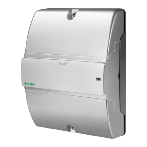
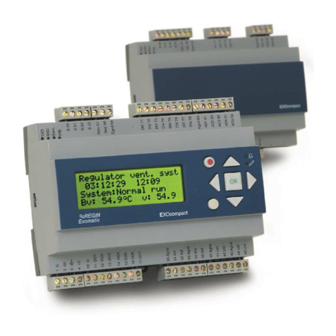
Regin Corrigo U10 Series User manual

U10...20
User manual

2ManualCORRIGO U-SERIE 2002-09
Contents
Modeloverview U10- U20 ............................................................................. 3
Technicaldata ............................................................................................... 3
OverviewU10................................................................................................. 4
OverviewU20................................................................................................. 5
Installation..................................................................................................... 6
Wiringdiagrams ............................................................................................ 7
DescriptionInputs ......................................................................................... 9
DescriptionOutputs ...................................................................................... 10
Using the CORRIGO - Menu system ................................................................ 12
Alarmhandling- alarm queue........................................................................ 14
Login ............................................................................................................. 14
Configuration ................................................................................................. 16
ControlHS1 .................................................................................................. 20
ControlHS2 .................................................................................................. 21
ControlTHW ................................................................................................. 21
Inputs............................................................................................................ 21
Outputs......................................................................................................... 21
Scheduler...................................................................................................... 23
Alarmsettingsandalarmqueue.................................................................... 24
Settings(other) ............................................................................................. 25
ConfigurationtableU10 ................................................................................. 27
ConfigurationtableU20 ................................................................................. 29
Index ............................................................................................................. 31
Introduction
CORRIGO U-seriesisacompletelynew range of digital controllersdesignedfor
controllingofdistrictheatingsub-stations and boiler stations.Thecontrollershavea
displayandbuiltinpanels for operation andalarmonthefront and are operated by
meansofclearlydefined buttons.
Thecontrollershavebeen designed formountingona DIN rail,innormhousing or on
the front of a cabinet.
The required functions are selected with the help of questions in normal script or by
meansofacode under the configurationmenudependingon the type ofapplication.
CORRIGO U-serieshas temperature sensorinputsfor outgoing radiator-watertempera-
ture,returnwater,room,hot tap-waterand outdoortemperature.
It can control actuators with 0...10 V DC control signal or 3-point floating control
actuators.
Theunitalsohasoutputsforcontrollingcirculationpumpsandinputs for pump
monitoringandsystem-pressurealarmaswellas an external alarm.
CorrigoU20hasayear-base real-time clock, night-setback scheduler,holiday
calendar, holidayperiodsandautomatic normal time/daylightsavingtimechange-
over.
During normal operation, without pressing any buttons, the display also shows the
mostimportantoperatingstatuses such as setpoint/currentvalue,sequence-output
controland time/date/versionetc.
We hope you will be satisfied with your CORRIGO and that it will provide you with
simpler and more economic running of your control systems.
3
Manual CORRIGO U-SERIE 2002-09
Technical data
Supplyvoltage 24VAC +/- 15%
Powerconsumption 3VA
Ambienttemperature 0...50deg.C.
Storagetemperature -40...+50deg.C.
Ambienthumidity Maximum90%RH
Dimensions (w x h x d) 105 x 112 (incl.terminals) x 58 mm.
Protection class IP20.Frontmounting IP40
Mounting On DIN-rail in acabinetorstandard housing.
On cabinet front using mounting kit FMC
Connections Disconnectableterminalstrips
Temp.sensor inputs PT1000
Analogueinputs 0....10VDC
Digitalinputs Potentialfreeclosure.
Digitaloutputs 0.5 A, 24 VAC triac outputs
Analogueoutputs 0...10 V DC, 5 mA. Short-circuit protected
Memory Flash.All settings are stored in the event of power failure.
Real-timeclockwith48 hour reserverunningtime.
Display Backgroundillumination.LCD,2 rows of 16characters
Runningindication 7 in number steady shining yellow LEDs
Alarmindication 7innumber steady shining/flashing redLEDs
Alarms Steadyshining/flashingLEDand relay output,
1A24VDC/AC.
Thealarmoutputcan beblockedtoprevent unprioritised
alarmsactivatingthealarm relay during thenightorduring
holidays.
Thisproductconformswith therequirementsof
EuropeanEMCstandards CENELECEN50081-1and
EN50082-1andcarriesthe CE mark.
Overview - models for heating control
CORRIGO for heating control is available in two models which differ slightly in their
controlfunctionandinthe number of inputsandoutputs.Bothmodels are available
without,U10and U20orwith,U10-LON andU20-LONcommunicationvia LON
Works.
Control radiator group
Control tap hot-water
Control tap hot-water primary circuit
Temperature logging of min/max values
Analogue inputs (PT1000)
Digital inputs
Analogue outputs (0...10 V)
Digital outputs
Output indication with yellow LEDs
Alarm indication in script and red LEDs
Night set-back, two levels
Automatic pump stop with daily exercising
Flash memory (all settings are saved in the event of power failiure)
Realtime clock (48 hours running reserve)
Year base clock
Communicaton (Lon-versions)
Clock controlled outputs
12
11
11
••
68
45
36
47
••
••
••
••
••
••
••
••
02
U10 U20

4ManualCORRIGO U-SERIE 2002-09
Analogue outputs - output signal 0...10 V
AO1 ControlvalveHS1-CV1
AO2 ControlvalveHW-CV1 or
ControlvalveTHW-CV1
AO3 ControlvalveTHW-CV1or
ControlvalveTHW-CV2
AO4 Not used
AO5 Not used
AO6 Not used
Digital outputs
DO1 Controloutput,pumpHS1
DO2 Three-positionoutput VS1increase
DO3 Three-positionoutput VS1decrease
DO4 Notused
DO5 Notused
DO6 Notused
DO7Alarmoutput
Overview
6analoguesensorinputs Pt1000
4 digital inputs
3 analogue outputs 0...10 V
4 digital outputs
Thecontrollerhasoutdoor temperature dependantheatingcontrolof one radiatorsystemHS1using one control
valve(HS1-CV1).Also control of taphot-waterusingeither one or twoseparatecontrol circuts HWandTHW or
asinglecontrolcircuitwith two sequences THW-CV1andTHW-CV2.
CORRIGO - U10
Analogue inputs - Temperature sensors
AI1 Outdoortemperature
AI2 HS1Supply temperature
AI3 HS1 Roomtemperatureor
HWCReturntemperatur taphot-water
AI4 HS1 Returntemperatureradiatorsystem or
HP1Supplyor
HWCReturntemperature taphot-water
AI5 HW Supply or
HP1Return
AI6 THWSupply
AI7 Notused
AI8 Notused
Digital inputs - runtime and alarm indication
DI1 Indication circulation pumpHS1
DI2 Indication circulation pumpHWC
DI3 Alarm from expansionvessel
DI4 External alarm
DI5 Not used
DI6 Not used
DI7 Not used
DI8 Not used

5
Manual CORRIGO U-SERIE 2002-09
CORRIGO - U20
Analogue inputs - Temperature sensors
AI1 Outdoortemperature
AI2 HS1Supply temperature
AI3 HS1 Roomtemperatureor
HWCReturntemperatur taphot-water
AI4 HS1 Returntemperatureradiatorsystem or
HP1Supplyor
HWCReturntemperature taphot-water
AI5 HW Supply or
HP1Return
AI6 THWSupply
AI7 HS2Supply temperature
AI8 HS2 Roomtemperatureor
HS2Returntemperatureradiator system
Digital inputs - runtime and alarm indication
DI1 Indication circulation pumpHS1
DI2 Indication circulation pumpHWC
DI3 Alarm from expansionvessel
DI4 External alarm
DI5 Not used
DI6 Indication cirkulation pumpHS2
DI7 Not used
DI8 Not used
Analogue outputs - output signal 0...10 V
AO1 ControlvalveHS1-CV1
AO2 ControlvalveHW-CV1 or
ControlvalveTHW-CV1
AO3 ControlvalveTHW-CV1or
ControlvalveTHW-CV2
AO4 ControlvalveHS2-CV1
AO5 ControlvalveHS1-CV2
AO6 ControlvalveHS2-CV2
Digital outputs
DO1 Controloutput,pumpHS1
DO2 Three-positionoutput VS1increase
DO3 Three-positionoutput VS1decrease
DO4 Controloutput,pumpHS2
DO5 Three-positionoutput VS2increaseor
TimeroutputTO1
DO6 Three-positionoutput VS2decreaseor
TimeroutputTO2
DO7Alarmoutput
8analoguesensorinputs Pt1000
5 digital inputs
6 analogue outputs 0...10 V
7 digital outputs
Thecontrollerhasoutdoor temperature dependantheatingcontrolof two radiatorsystemsHS1andHS2 using
foreachoneor twocontrolvalves(HS1-CV1, HS1-CV2 andHS2-CV1,HS2-CV2).Alsocontroloftap hot-water
using either one or two separate control circuts HW and THW or a single control circuit with two sequences
THW-CV1andTHW-CV2.Alsotwo independent timer outputsTO1andTO2forcontrollingexternal functions
such as door locks, lighting etc.

6ManualCORRIGO U-SERIE 2002-09
Installation
CORRIGO can be mounted in standard casing, on a DIN rail in a cabinet or in the front
of a cabinet.
Front mounting kit
When CORRIGO is to be placed in a cabinet front mounting will be facilitated using the
front mounting kit FMK1. The kit contains a front frame with see-through lid and an
integratedmounting-rail.
When placing two CORRIGOs or one CORRIGO and one relay unit RM6..-24/D next to
each other in the front of the cabinet use the FMCR mounting kit. It contains the
samepartsasFMCabove but they areofdifferentdimensions.
Supply voltage
The controller is to be supplied with 24VAC. Terminal 43, system neutral, is
internallyconnectedtoterminal41, signal neutral fortheanalogueoutputs,and
terminals 24, 27, 30 och 33, signal neutral for the analogue inputs.
Inputs
Thecontrollerhascommonpolesfor signal neutral to transmitters (AI1-8)anda
common pole for digital input signals.
Terminal 22 (common for digital input signals) is not the same as signal neutral for
transmitters ( terminals 24,27,30 and 33) and they must not be interconnected.
Signalneutralterminalsfor transmitters(24,27,30and33) are, however,internally
connected and connected to system neutral on terminal 43.
Outputs
Theanalogueoutputsgive0...10 V DC. Signal neutralonterminal41isinternally
connected to system neutral on terminal 43.
Digital outputs are supplied in pairs with 24VAC on the terminals which are marked
with 24VAC in (terminals 6,9 and 12). Each output has an internal triac which gives
24VAC.
Service pin
OntheLON-modelsthecomissioning service pin islocatedbehindamarked opening
on the upper side of the CORRIGO.
Important!
AI1...AI8analoguein
AO1...AO6analogueout
Supplyvoltage24 VAC
DO1...DO7digitaloutputs
DI1...DI8digitalinputs
Servicepin(LON models)
Display contrast setting

7
Manual CORRIGO U-SERIE 2002-09
Wiring diagram U10
1
2
3
4
5
6
7
8
9
10
11
12
13
14
15
16
17
18
19
20
21
22
23
24
25
26
27
28
29
30
31
32
33
34
35
36
37
38
39
40
41
42
43
44
24 V AC
1A
24 V AC/DC
Net A LON-connection U10-LON only
Net B LON-connection U10-LON only
DO7 Alarm output
DO7 Alarm output
DO6 Not connected
Not connected
DO5 Not connected
DO4 Not connected
24 V AC in DO3/DO4
DO3 3p. outp. HS1-CV1 - decrease
DO2 3p. outp. HS1-CV1 - increase
24 V AC in DO1/DO2
DO1 Control Pump HS1-P
DI8 Not connected
DI7
Not connected
DI6 Not connected
DI5
Not connected
DI4 External alarm
DI3 Alarm expansion vessel
DI2 Monitor pump HWC-P
DI1 Monitor pump HS1-P
Common DI1-DI8
AI1 Temperature outdoor
Signal neutral
AI2 Temperature HS1 Outgoing
AI3 Temperature HS1 Room / HWC
Signal neutral
AI4 Temperature HS1 Return / HP1 Outgoing
AI5 Temperature HW Outgoing / HP1 Return
Signal neutral
AI6 Temperature THW Outgoing
AI7 Not connected
Signal neutral
AI8 Not connected
AO1 HS1-CV1 0...10 V DC
AO2 HW-CV1 / THW-CV1 0..10 V DC
AO3 THW-CV1 / THW-CV2 0..10 V DC
AO4 Not connected
AO5 Not connected
AO6 Not connected
Signal neutral for AO1-AO3
G Supply voltage 24 V AC
G0 System neutral
Earth

8ManualCORRIGO U-SERIE 2002-09
Wiring diagram U20
1
2
3
4
5
6
7
8
9
10
11
12
13
14
15
16
17
18
19
20
21
22
23
24
25
26
27
28
29
30
31
32
33
34
35
36
37
38
39
40
41
42
43
44
Net A LON-connection U20-LON only
Net B LON-connection U20-LON only
DO7 Alarm output
DO7 Alarm output
DO6 3p. outp. HS2-CV1 - decrease / TO1
24 V AC in DO5/DO6
DO5 3p. outp. HS2-CV1 - increase / TU2
DO4 Control Pump HS2-P
24 V AC in DO3/DO4
DO3 3p. outp. HS1-CV1 - decrease
DO2 3p. outp. HS1-CV1 - increase
24 V AC in DO1/DO2
DO1 Control Pump HS1-P
DI8 Not connected
DI7
Not connected
DI6 Monitor pump HS2-P
DI5
Not connected
DI4 External alarm
DI3 Alarm expansion vessel
DI2 Monitor pump HWC-P
DI1 Monitor pump HS1-P
Common DI1-DI8
AI1 Temperature outdoor
Signal neutral
AI2 Temperature HS1 Outgoing
AI3 Temperature HS1 Room / HWC
Signal neutral
AI4 Temperature HS1 Return / HP1 Tillopp
AI5 Temperature HW Outgoing / HP1 Return
Signal neutral
AI6 Temperature THW Outgoing
AI7 Temperature HS2 Outgoing
Signal neutral
AI8 Temperature HS2 Room / HS2 Return
AO1 HS1-CV1 0...10 V DC
AO2 HW-CV1 / THW-CV1 0..10 V DC
AO3 THW-CV1 / THW-CV2 0..10 V DC
AO4 HS2-CV1 0...10 V DC
AO5 HS1-CV2 0...10 V DC
AO6 HS2-CV2 0...10 V DC
Signal neutral for AO1-AO6
G Supply voltage 24 V AC
G0 System neutral
Earth
1A
24 V AC/DC
24 V AC

9
Manual CORRIGO U-SERIE 2002-09
AIAnalogue inputs
CORRIGO hasanalogueinputsAIforconnecting temperature sensors. PT1000type
temperaturesensorsmustbeused. The function ofsomeoftheinputs varies
dependingonthechoice ofmodelandconfiguration.
AI-inputs must always use the signal neutral of theAI terminal block as reference.
(terminals 24, 27, 30 or 33).
AI1 Outdoortemperaturesensor.Mustalwaysbeinstalled.
AI2 HS1Outgoingwatertemperature. The temperatureatthesensor is controlled
by the controlvalve HS1-CV1 so that the calculated setpoint is held. The set-
pointdependsonthe set controlcurveandtheoutdoor temperature. Thesensor
should be placed so that it senses the outgoing-water temperature in the
radiatorcircuitafter thecontrolvalve.
AI3 HS1Roomtemperature or HWC
Aroomtemperaturesensor should be placedatalocation with a representative
temperature.Thetemperaturesignal isusedtogive a roomtemperature
dependantdisplacementof theradiator-watersetpoint.
TheK-factorgoverning theratiobetween roomtemperatureoffset andwater
temperature displacement is set in the menu ”Settings”.
A HWC (Hot water circulation) sensor is not used in any control-function but
onlyfordataacquisition.
AI4 HS1returntemperature or HP1(Heating,primary)
The sensor reading is not used in any control-function but only for data
acquisition.
AI5 HWOutgoingtemperature orHP1return
Thetemperatureatthesensor is controlled bythecontrolvalveHW-CV1so that
the setpoint is held.
A HP1 return sensor is not used in any control-function but only for data
acquisition.
AI6 THWoutgoingtemperature
Thetemperatureatthe sensor iscontrolledbythe controlvalve THW-CV1so
that the setpoint is held.
AI7 HS2Outgoingtemperature.Thetemperature at the sensoriscontrolledby the
controlvalveHS1-CV1sothatthe calculated setpoint isheld.Thesetpoint
dependsontheset control curveandtheoutdoor temperature. Thesensor
should be placed so that it senses the outgoing-water temperature in the
radiatorcircuitafter thecontrolvalve.
AI8 HS2roomtemperatureor VS2return
Aroomtemperaturesensor should be placedatalocation with a representative
temperature.Thetemperaturesignal isusedtogive a roomtemperature
dependantdisplacementof theradiator-watersetpoint.
TheK-factorgoverning theratiobetween roomtemperatureoffset andwater
temperature displacement is set in the menu ”Settings”.
A HS2 return sensor is not used in any control-function but only for data
acquisition.
Wiring
(CORRIGO U20only)
(CORRIGO U20only)

10 ManualCORRIGO U-SERIE 2002-09
Analogue outputsAO
CORRIGO hasanalogueoutputsAO forcontrollingactuators
Output signal 0...10 V DC, 5 mA. Short-circuit protected.
Theseoutputsshouldrefer to terminal 41,signalneutral.
Signal neutral, terminal 41, in the CORRIGO is internally connected to sytem neutral
G0onterminal43.
Itisthereforeimportantthatanyactuators sharing the CORRIGO supplytransformer
are wired with their supply neutral connected to the same transformer pole as the
CORRIGO terminal43.
AO1 ControlvalveHS1-CV1
AO1 is only active if HS1-CV1 has been configured as a 0...10 V actuator. See
underConfiguration.
AO2 Controlvalve HW-CV1orTHW-CV1
AO3 Controlvalve THW-CV1orTHW-CV2
AO4 ControlvalveHS2-CV1 (C20only)
AO4 is only active if HS2-CV1 has been configured as a 0...10 V actuator. See
underConfiguration.
AO5 ControlvalveHS1-CV2 (C20only)
AO5 is only active if HS1 has been configured for two actuators in sequence.
SeeConfiguration.
AO6 ControlvalveHS2-CV2 (C20only)
AO5 is only active if HS2 has been configured for two actuators in sequence.
SeeConfiguration.
Digital inputs DI
CORRIGO hasdigitalinputsDIforactivation of certain functions andinputofexternal
alarmsignals.
Theseinputsmayonly be wiredtovoltage-freecontacts.
These inputs may only refer to the common DI pole on terminal 22.
Terminal 22 does not have the same potential as other signal neutrals in the CORRIGO
and may not be connected to any other terminals except the DI inputs.
Theinputsareconfiguredsuchthataclosedcontactwillactivatethe function/alarm
DI1 IndicationcirculationpumpHS1
DI2 IndicationcirculationpumpHWC
DI3 Expansionvesselpressure alarm
DI4 Externalalarm
DI5 Notused
DI6 IndicationcirculationpumpHS2 (C20 only)
DI7 Notused
DI8 Notused
N.B.
Important
Wiring

11
Manual CORRIGO U-SERIE 2002-09
Wiring
Digitala utgångar DO
CORRIGO has 7 digital outputs DO1...DO7.
DO7, alarm output is a voltage free closing relay contact. 1A, 24 VAC/DC.
The outputs DO1...DO6 are triac controlled, 0.5A, 24 VAC. Short term 1A.
The triac outputs are paired to common supply terminals for 24 VAC.
Seefigureinthe margin.
DO1 Controlofcirculationpump HS1
DO2 3-pointoutputHS1-CV1 increase
DO3 3-pointoutputHS1-CV1 decrease
DO2andDO3 are onlyactiveifHS1-CV1 hasbeenconfiguredfor 3-point
floatingcontrol.
SeeunderConfiguration.
DO4 Controlofcirculationpump HS2
DO5 3-pointoutputHS2-CV1 increase or
TO1timeroutput
DO6 3-pointoutputHS2-CV1 decreaseor
TO2timeroutput.
DO7 Alarmoutput.Potentialfreerelay, normally open.
1A, 24 VAC/DC.
5
6
7
24 V AC in
DO5 ut
DO6 ut

12 ManualCORRIGO U-SERIE 2002-09
Buttons on the front
Arrowup–moveupwards in the menu.Inthe”Change”position the
button is used to INCREASE the value indicated. When the button is held
in a depressed position the function is repeated.
Arrowdown–move downwards inthemenu.In the”Change”modethe
button is used to DECREASE the value indicated. When the button is
held in a depressed position the function is repeated.
Thisisusedtostop an ongoing operationortomoveone level upwards in
the menu. The Esc button is also used to move backwards in the menus
whichcontainanumberofvalues,thusit is possible to move forwards
withOKand backwards withEsc.
(enter). Is used to confirm an item in the menu. In the ”Change”mode the
button is used to confirm a set value and/or to continue to the next set-
ting. Help menus: Press OK and the controller will show an explanatory
text for the menu in question, provided that the menu is not in the
”Change”position.
Alarm –opens the alarm queue. Press this button and active and non-
acknowledgedalarmswillbe displayed inthemenuwindow.The LEDfor
alarms placed above the alarm button is lit when there are alarms in the
queue. If there are multiple alarms use andto move between them.
An alarm can be acknowledged by using OK. To abort, press Esc.
Change–Goesoverto ”Change”mode. Usethisbuttontochange
something in a menu, for example, a setpoint. You remain in the ”Change”
modeuntilyouhaveconfirmed the changebymeansofOK
orabortedtheoperation by means ofEsc.Ifthebuttonsare not activated
thecontrollerwillstopthe operation automatically after
a minute or so.
Changing language
CORRIGO is supplied with the script in English.Apart from English, CORRIGO can also
be set to use any of a number of other languages.
Thelanguageselectionfunction is activated byholdingthebutton depressed
duringpowerup.The languagemenuisthen shown:
Tochangelanguagepress! again andthemarkerwillshow the currentlanguage.
Select the desired language by using the arrow buttons. Press OK to acknowlege.
When the language has been changed or if no change is to be made, press OK and
the controller’s normal menu system will start up.
Esc
OK
Language/Språk
English

13
Manual CORRIGO U-SERIE 2002-09
Information series - rolling display
During normal running when the buttons are not in use a series of menu pages is
shown.
Thedisplayalternatesbetweena general display withproductdescriptionandclock,
setpoint/actual temperature, output status for the control outputs Y1,Y2 and Y3 and
setpoint, actual value and output status for supply air fan and exhaust air fan and
sepointandactualvaluefor the humidity control.
The initial display shows the product name, date and time.
Program version number By pressing Esc when the gerneral display is active the
productversionnumberis displayed. ForLON-modelsthe12 digit neuron
ID-numberisalsodisplayed
Theinformationmenuisstarted by leaving the mainmenubymeansof Esc or by
leavingthekeyboardunusedfor a ten-minute period.First,thestartwindow will be
shownfor10secondsand then the three displaysshownabovewillalternate at
three-secondintervals.
Main menu
Press the OK button.Theinformationmenuwillstopandthemain menu will open
immediately.
The main menu consists of a number of menu headings and what can be seen and
doneisgovernedby the log-in leveloftheuser,as describedbelow.
When the main menu is opened CONTROL HS1 is always displayed at the top of the
display.
Thearrowmarkertothe left of CONTROLHS1meansthatthis heading is marked
and pressing the OK button opens this menu and shows its submenus.
Arrowsattherightof the display indicatethatthereareheadingsabove and below
the text that is currently being displayed. Move by using the arrow buttons.
Themainmenuhas thefollowingheadings:
Login
Configuration Only shown at user level 3
Control HS1
Control HS2 (CORRIGO U20only)
Control HW/THW
AIAnalogue in
DI Digital in
AOAnalogue out
DO Digital out
Scheduler
Alarm settings Notshowninlevel 0
Settings Only shown in level 2 and 3
>Control HS1
Control HS2
*CORRIGOU20* VS1Börv/Ärvärde VVBörv/Ärv/Utst
Må98090710:10 25.0ºC / 25.0ºC 60°C/60°C/45%

14 ManualCORRIGO U-SERIE 2002-09
Alarms
When alarms are activated they are displayed in the alarm queue and also as a
blinking red light on the display panel on the front of the controller. Certain alarms
cannotbetracedtoone of the 7LEDsonthepanel and therefore have noseparate
alarmonthefront.The alarm lamp abovethealarmbuttonalways blinks red,
however, intheevent ofanalarm.
Alarm queue
To check the alarm queue press the alarm button . The display will then show
active alarms, the date and time when the alarm became active and the alarm status.
Alarmstatus
Blinking ”AL”indicates that the alarm is active and has not been acknowledged.
Steady ”AL”indicates that the alarm is active but has been acknowledged.
Blinking ”OK”indicates that the alarm has aborted but has not been acknowledged.
Acknowledging an alarm
Alarmsareacknowledgedbymeans of the OKbuttonwhich will remove thealarm
from the alarm list. If the alarms are still active they will remain in the alarm list but
the blinking will be replaced by a steady ”AL”and a steady red light on the alarm
signals.
Arrowsontheright-handside show when therearemorealarmsin the queue.
Login
CORRIGOhasfour differentloginlevels topreventthe userfrominadvertently
changing any settings.
0 Without logging in all of the most important parameters can be viewed such as
input and output status, alarms in the alarm queue, setpoints etc.Alarms can
alsobeacknowledged.
1 Main setpoint, time and date can be set. Outputs can be manually set and the
runningmodecanbesettomanuallyonoroff. Other parameters can be read
off butnotchanged.
2 Gives access to most setpoints and running parameters such as outdoor
compensation, control alarm deviations, time delays etc.
3 The highest user level giving total access. Used by the commissioning
engineerforsystem configuration.
Menu information
If the user attempts to make changes that cannot be made or which lie outside his
userlevelthecontroller will displaythefollowinginformation:
Unauthorised
Make new logon
No changes in
this menu
Control HS1-P
AL 80 25 14:20
Menu help text
There are extra help-text to most of the menu pages. By pressing the OK button
(except when in ”Change mode”) the extra text will be displayed.

15
Manual CORRIGO U-SERIE 2002-09
Important!
To log in to another user level.
Press or until the cursor arrow points at Login. Press OK.
Theloginmenuwill be displayed.
To log in press and a marker will be shown on the first digit. Press to change
thevalue.
Press OK to move to the next digit. To return to the previous digit press Esc.After
the last digit the code is evaluated.
Theoperationcan be abortedbymeansof Esc.
If an incorrect code is given an error message is displayed:
Thecorrectcodewillresult in anacknowledgingmessageshowingthe login level.
After 2 seconds the system automatically returns to the main menu.
Factory set codes
Thecodesforthethreeuserlevelsarefactory set as follows
Userlevel1 1111
Userlevel2 2222
Userlevel3 3333
Changing codes
The codes for the three user levels can easily be changed in user level 3.
Entertheloginmenu:
Thearrowmeansthat there are menusbelow, press thearrowuntilthecode for level
1, 2 or 3 is displayed.
Change the code using .The cursor will start on the first digit. Change using the
arrow buttons. To move to the next digit press OK. To return to the previous digit
pressEsc.
By pressing OK after the last digit the code will be registered. To abort use Esc.
DONOTFORGETTOMEMORIZE THE NEWCODESortowrite them down. Thisis
especially important for user level 3. Should the code for level three be lost the sys-
tem can be opened by means of a code number which can be obtained from
REGIN.Thiscodenumber is timedependent.
Set your code
0000 Level:0
Incorrect code
try again
Login ok
Code:0
Set your code
0000 Level:3
Code for level1
1111
Code for level2
2222
Code for level3
3333

16 ManualCORRIGO U-SERIE 2002-09
Exampleofconfiguration
table
KONFIG. KOD 1
0011.1110.0000
KONFIG. KOD 2
0100.0100.11
KONFIGURERING-CORRIGO U20 A B C D . E F G H . I J K L
Konfigureringskod 1 1 . .
AFunctionsensor AI1
1.Outdoor sensor (Can notbechanged) 1
BFunctionsensorAI2
0.---Input not active 0
1.HS1Supply 1
CFunctionsensorAI3
0.---Input not active 0
1.HS1 Room sensor 1
2.HWC Return 2
DFunctionsensorAI4
0.---Input not active 0
1.HS1Return 1
2.HPSupply 2
EFunctionsensorAI5
0.---Input not active 0
1.HWSupply 1
2.HPReturn 2
FFunctionsensorAI6
0.---Input not active 0
1.THWSupply 1
G Function sensor AI7 (C20only)
0.--- Ingången ej aktiv 0
1.HS2Supply 1
H Function sensor AI8 (C20only)
0.---Input not active 0
1.HS2 Room sensor 1
2.HS2Return 2
INightsetbackVS1
0.No 0
1.Yes 1
JRoomcompensationVS1
0.No 0
1.Yes 1
KVS1-SV1type
0.0...10VDC 0
1.3-point 1
LVS1-SV2 (C20only)
0.No 0
1.Yes 1
Configuration
Configuration implies the commissioning setting of all the parameters in the CORRIGO.
Parameters are set using script.
Configuration codes
There is also the option of setting parameters by means of two configuration codes.
Thisfunctionisparticularly useful andtime-savingwhena number ofcontrollersare
to be configured in the same way.
The first thing to be shown when the configuration menu is opened is the setting of
thecontrolfunction.
Usingthearrowupbutton the two configurationcodeswillbedisplayed and the arrow
downbuttonwillgivethe parameters oftheotherconfigurationsin script.
Thecodedigitsinthe configuration code correspondtothescriptparameters below
innumericalsequence.This meansthatthefirstdigit in CONFIG.CODE1 determines
which control function the controller is to work with. The second digit refers to heater
type etc.
Before the corresponding selection in the script parameters there is a digit which
corresponds to the code number in the configuration code. See the details below.
Tables for configuration code
There is also a special table to facilitate the choice of configuration code. This is
always supplied together with the CORRIGO instruction sheet.
In the table all the configuration parameters are shown as well as the selections that
can be made. Basic selections are marked in bold type.
Bygoingthroughthe parameters and fillinginthefiguresbeside the respective
selections the configuration code can be obtained without difficulty. This can also act
as a protocol of settings for CORRIGO.
Automatic restart after changing
Whenoneormore parameters havebeenchangedthe controller willrestartwhenthe
userleavesthe configurationmenu.

17
Manual CORRIGO U-SERIE 2002-09
Configuration
Some of the functions are not available on all models. This due to that some of the
inputsoroutputs have alternativefunctions.
A. Function sensor AI1
1. Outdoor sensor. Fixed setting. Do not change
Sincetheheatingcontrolisoutdoortemperature dependant this sensor must
beinstalledandconfigured forcorrectfunction.
B. Function sensor AI2
0. --- Input not active
1. HS1Supply.
AI2 must be configured as HS1 Supply if the sequence HS1is to be used for
heatingcontrol.
Thetemperatureatthe sensor is controlledbythecontrolvalve HS1-CV1 so
that the calculated setpoint is obtained. The setpoint depends on the control
curve which is set in the menu ”Control HS1”.
C. Function sensor AI3
0. --- Input not active
1. HS1Roomsensor.
AI3 must be configured as HS1 Room sensor if the sequence HS1is to have
roomtemperaturecompensation.
The sensor signal will displace the control curve to compensate the supply
watertemperaturefor any offsetinroom temperature.
theK-factordeterminingthe room temperature influenceonthesetpointmust
be set in the menu ”Settings”.
2. HWCReturntemperaturein the tap hot watercirculation.
A HWC (Hot water circulation) sensor is not used in any control-function but
onlyfordataacquisition.
D. Function sensor AI4
0. --- Input not active
1. HS1Return
2. HPSupply
The sensor reading is not used in any control-function but only for data
acquisition.
E. Function sensor AI5
0. --- Input not active
1. HW Supply
Must be configured to obtain the HW circuit.
Thetemperatureatthesensor is controlled bythecontrolvalveHW-CV1 so
that the setpoint temperature is held.
The setpoint is set in the menu ”Control HW/THW.
2. HPReturn
The sensor reading is not used in any control-function but only for data
acquisition.
F. Function sensor AI6
0. --- Input not active
1. THWSupply
Must be configured to obtain the THW circuit.
Thetemperatureatthe sensor is controlledbythecontrol valve THW-CV1 so
that the setpoint temperature is held.
The setpoint is set in the menu ”Control HW/THW.

18 ManualCORRIGO U-SERIE 2002-09
G. Function sensorAI7 (CORRIGO U20 only)
0. --- Input not active
1. HS2Supply.
Must be configured as HS2 Supply if the sequence HS2is to be used for
heatingcontrol.
Function as forAI2, see point B.
H. Function sensor AI8 (CORRIGO U20 only)
0. --- Input not active
1. HS2Roomsensor.
AI8 must be configured as room sensor if HS2 is to have room compensation.
Function as forAI3, see point C.
2. HS2Return
The sensor reading is not used in any control-function but only for data
acquisition.
I. Night set-back HS1
0. No
1. Yes
CORRIGO hasthepossibilityofsheduler controlled room temperature set-back
to two different levels, night set-back and stand-by set-back, the latter
normallyusedforshuttingthe system down for longerperiods.Alarger
temperatureloweringis normallyprogrammed.
The size of the set-back is set in the menu ”Control HS1”.
Setting of time and date is in the menu ”Scheduler”.
Ifnoroomsensorisconfigured the controller will calculatetheloweringofthe
watertemperatureusingthe current outdoortemperatureandthe set K-factor
fortheroom.
J. Room compensation HS1
0. No
1. Yes
IsonlyshownifAI3 has been configured asroomsensor.Anyroom tempera-
turedeviationwilldisplacethe setpoint for thewatertemperaturesothatthe
deviationiseliminated.
K. HS1-CV1 type
0. 0...10VDC
Controls the actuator using an analogue 0...10 V DC signal on outputAO1.
Controlparametersareset in the menu”ControlHS1”.
1. 3-point
Controlstheactuatorusingincrease/decrease signals on the outputsDO2and
DO3.Controlparametersare set in themenu”ControlHS1”.
L. HS1-CV2 (CORRIGO U20only)
0. No
1. Yes
DeterminswhetherHS1should have oneortwosequences.Is automatically
set to No if CV1 has been set to 3-point since CORRIGO U only can sequence
0...10V outputs.
M. Night set-back HS2 (CORRIGO U20only)
Seecorrespondingfunction for HS1underpointI.
0. No
1. Yes
N. Room compensation HS2 (CORRIGO U20 only)
Seecorrespondingfunction for HS1underpointJ.
0. No
1. Yes
Is only shown ifAI8 is configured as room sensor.

19
Manual CORRIGO U-SERIE 2002-09
O. HS2-CV1 typ (CORRIGO U20 only)
0. 0...10VDC
Controls the actuator using an analogue 0...10 V DC signal on outputAO1.
Controlparametersareset in the menu”ControlHS2”.
1. 3-point
Controlstheactuatorusingincrease/decrease signals on the outputsDO5and
DO6.Controlparametersare set in themenu”ControlHS2”.
N.B. 3-point control of HS2-CV1 can not be combined with the use of the timer
outputsTO1and TO2.
P. HS2-CV2 (CORRIGO U20only)
Seecorrespondingfunctionfor HS1underpointL.
0. No
1. Yes
Q. Control THW
0. 1sequence
1. 2sequences
R. Control HW
0. No
1. Yes
Not shown if THW is set to 2 sequences
S. Pump control HS1
0. No
1. Yes
Parameters for the pump control are set in the menu ”Settings”.
Stopped pump is exercised daily.
T. Pump control HS2 (CORRIGO U20 only)
0. No
1. Yes
U. Pump indication HWC
0. No
1. Yes
AbsenceofsignalfromHWC-P on DI2 will triggeranalarm.
V. Daylight saving time
0. No
1. Yes
Yes means automatic setting to summertime at 02:00 the last Sunday in
March. Reverts to normal time at 03:00 the last Sunday in October.
X. Basic settings
Use this function to reset to factory settings. Press the ”change”button,
choose”Yes”and confirm with OK.
To abort atthe”change”stage,press Esc.
All parameters and settings revert to the original factory settings if the
command ”Basic Settings”is used.
This command should only be used by the commissioning engineer.
Whentheconfigurationisdone and the configurationmenuisexitedusing Esc an
automaticrestartwiththenewparameters will occur.
The login level is reset to 0.

20 ManualCORRIGO U-SERIE 2002-09
Konfigurering, snabbmetod
Atthetopof the configuration branchtherearetwomenues, Configuration code 1
andConfigurationcode 2.
Each position in the code corresponds, in order, to hte menuesAto V described on
thepreviouspages.
The codes may be set directly in these two menues.
Tables for configuration code
There is also a special table to facilitate the choice of configuration code. This is
always supplied together with the CORRIGO instruction sheet.
Control HS1
In this menu branch you can look at and set most control values for the temperature
controlofHS1.
See also the menu branch ”Settings”.
Which of the menues below that will be shown and which will be settable depends on
theconfigurationandthepresent login level.Thetableshowsall the menues.
1 Setpoint /Actual temp/Output.
Output is only shown if HS1 is configured with 1 sequence. When HS1 is
configured as 3-point , output is shown as + or -.
2 HS1 Y1 / Y2 Output %. Only shown if HS1 is configured with 2 sequences.
3 Manual offset /Actual setpoint.
Thecontrolcurvecan be offset ±30K/Setpointincludingoffset.
4 Setpoint Room /Actual Room / Room compensation.
Display only. Change of room temp in next menu
5 SetpointRoom.
6 Runningmode/Actual night reduction
7 Nightreduction/Standby reduction
Settingofreductionof room temperatureindegrees.
If no room sensor is installed the lowering in water temperature is calculated
usingthegivenK-factor.SeeunderSettings.
8 Controlcurve.Breakpoint 1.
9 Controlcurve.Breakpoint 2.
10 Controlcurve.Breakpoint3.
11 Control curve.Breakpoint4.
12 Controlcurve.Breakpoint5.
13 Controlcurve.Breakpoint6.
14 Controlcurve.Breakpoint7.
The breakpoints must be placed with 1 at the
lowestand7atthe highest outdoor tempera-
ture.
Statetheoutdoor temperatureandoutgoing
watertemperaturefor eachpoint.
Outdoortemperatureslower thanthatgiven for
point1willgive a water temperatureequalto
that at point 1.
Outdoortemperatureshigher thanthatgiven for
point7willgive a water temperatureequalto
that at point 7.
4567
Watertemperature
Outdoortemperature
3
2
1
This manual suits for next models
1
Table of contents
Other Regin Controllers manuals

Regin
Regin ALD24A1 User manual

Regin
Regin REGIO RC-DTO User manual

Regin
Regin AQM2000A-1R User manual

Regin
Regin TTC80F User manual

Regin
Regin RVAN10-230 User manual

Regin
Regin RDAS18S Series User manual

Regin
Regin AQUA230T User manual

Regin
Regin RCF Series User manual

Regin
Regin RVAPC-24A User manual

Regin
Regin RVAZ4L1-24 User manual

Regin
Regin SPINN/D User manual

Regin
Regin REGIO RC-T User manual

Regin
Regin RVAN25-24 User manual

Regin
Regin RVAZ4-230 User manual

Regin
Regin Exigo User manual

Regin
Regin TTC25X User manual

Regin
Regin RVAN5-24A User manual

Regin
Regin REGIO EEDO User manual

Regin
Regin RVAR5-24A User manual

Regin
Regin RVAZ4-24 User manual