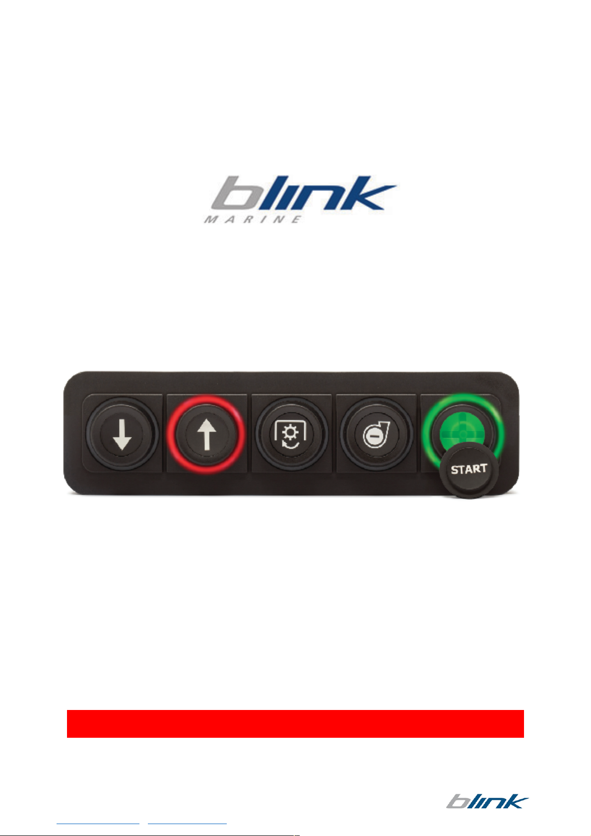
Blink Marine PKP-1500-LI User manual
Via$Montefeltro,$6$–$20156$Milano$(MI)$–$Italy$ $ $
Tel.$+39$(02)$3088583$–$Fax$+39$(02)$33406697$ $ $ $
www.blinkmarine.com$–$info@blinkgroup.com$ $ $ FOR REFERENCE ONLY!
PKP-1500-LI
CANOPEN USER MANUAL
$
$
THE PRESENT MANUAL IS FOR REFERENCE ONLY AND MIGHT BE NOT UP TO DATE TO THE LATEST
VERSION.PLEASE CONTACT US FOR GETTING THE MOST UPDATED FILE
$

$
Via Montefeltro, 6 – 20156 Milano (MI) – Italy - 2 -
Tel. +39 (02) 3088583 – Fax +39 (02) 33406697
www.blinkmarine.com – info@blinkgroup.com FOR REFERENCE ONLY
!!
Table of contents
1.$How$to$connect$the$wires:$..........................................................................................$3$
2.$Reference$....................................................................................................................$4$
3.$Default$settings$...........................................................................................................$5$
NMT$MESSAGES$..................................................................................................................$5$
4.$Start$CANopen$node$(keypad$activation$message)$.....................................................$5$
5.$Enter$pre-operational$..................................................................................................$5$
6.$Reset$CANopen$node$...................................................................................................$6$
7.$Stop$CANopen$node$....................................................................................................$6$
8.$Boot-up$service$............................................................................................................$6$
9.$Heartbeat$message$......................................................................................................$6$
10.$Sync$message$..............................................................................................................$7$
PDO$messages$.....................................................................................................................$7$
11.$Keys$state$message$.....................................................................................................$7$
$ -PKP$1500LI$................................................................................................................$7$
12.$Set$LED$ON$message$....................................................................................................$8$
$ -PKP$1500LI$................................................................................................................$8$
13.$Set$LED$Blink$message$.................................................................................................$8$
$ -PKP$1500LI$................................................................................................................$8$
14.$LED$indicators$brightness$level$....................................................................................$9$
15.$Backlight$brightness$level$............................................................................................$9$
SDO$Messages:$....................................................................................................................$9$
16.$Object$2000h:$Digital$input$module,$keys$states$.........................................................$9$
$ -PKP$1500LI$................................................................................................................$9$
17.$Object$2001h:$Digital$output$module.$.......................................................................$10$
a)$Set$LED$ON$.................................................................................................................$10$
$ -PKP$1500LI$..............................................................................................................$10$
b)$Read$LED$ON$..............................................................................................................$11$
$ -PKP$1500LI$..............................................................................................................$11$
18.$Object$2002h:$Digital$output$module.$.......................................................................$11$
a)$Set$LED$blink$..............................................................................................................$11$
$ -PKP$1500LI$..............................................................................................................$11$
b)$Read$LED$blink$...........................................................................................................$12$
$ -PKP$1500LI$..............................................................................................................$12$
19.$Object$2003h:$Brightness$Level$.................................................................................$12$
a)$LED$indicators$brightness$level:$...............................................................................$12$
b)$Backlight$brightness$level$........................................................................................$13$
$

$
Via Montefeltro, 6 – 20156 Milano (MI) – Italy - 3 -
Tel. +39 (02) 3088583 – Fax +39 (02) 33406697
www.blinkmarine.com – info@blinkgroup.com FOR REFERENCE ONLY
c)$Backlight$color$.........................................................................................................$14$
d)$Default$backlight$color$............................................................................................$14$
e)$Default$LED$indicators$brightness$level$...................................................................$15$
f)$Default$backlight$brightness$level$...........................................................................$16$
20.$Object$2010h:$Baud$rate$setting$...............................................................................$16$
21.$Object$2011h:$Set$Boot-up$service$............................................................................$17$
22.$Object$2012h:$Set$device$active$on$startup$...............................................................$18$
23.$Object$2013h:$Set$CANopen$node$ID$........................................................................$18$
24.$Object$2014h:$Set$startup$LED$show$.........................................................................$19$
25.$Object$2100h:$Set$DEMO$mode$.................................................................................$20$
26.$Object$1016h:$Consumer$heartbeat$time$..................................................................$20$
27.$Object$1017h:$Producer$heartbeat$time$...................................................................$21$
Heartbeat$message$...........................................................................................................$21$
28.$Object$1000h:$Device$Type$........................................................................................$22$
29.$Object$1001h:$Error$Register$.....................................................................................$22$
30.$Object$1008h:$Manufacturer$Device$Name$...............................................................$23$
31.$Object$1009h:$Manufacturer$Hardware$Revision$......................................................$23$
32.$Object$100Ah:$Manufacturer$Firmware$Revision$......................................................$24$
33.$Object$100Bh:$Model$ID$............................................................................................$24$
34.$Object$1011h:$Restore$default$parameters$...............................................................$25$
35.$Object$1018h:$Identity$Data$......................................................................................$25$
36.$Object$1400h:$Receive$PDO$Communication$Parm$0$................................................$26$
37.$Object$1401h:$Receive$PDO$communication$Parm$1$................................................$27$
38.$Object$1402h:$Receive$PDO$communication$Parm$2$................................................$28$
39.$Object$1403h:$Receive$PDO$communication$Parm$3$................................................$28$
40.$Object$1600h:$Receive$PDO$mapping$Parameter$0$...................................................$29$
41.$Object$1601h:$Receive$PDO$mapping$Parameter$1$...................................................$29$
42.$Object$1602h:$Receive$PDO$mapping$Parameter$2$...................................................$30$
43.$Object$1603h:$Receive$PDO$mapping$Parameter$3$...................................................$31$
44.$Object$1800h:$............................................................................................................$31$
a)$Transmit$PDO$Communication$Parm$0$....................................................................$31$
b)$Set$periodic$state$transmission$...............................................................................$32$
45.$Object$1A00h$Transmit$PDO$Mapping$Parameter$.....................................................$33$
46.$Object$2200h:$$Serial$number$string$..........................................................................$34$
47.$Set$CAN$protocol$.......................................................................................................$34$
APPENDIX:$DEMO$Mode$instructions$35$
$
$
$
$
$

$
Via Montefeltro, 6 – 20156 Milano (MI) – Italy - 4 -
Tel. +39 (02) 3088583 – Fax +39 (02) 33406697
www.blinkmarine.com – info@blinkgroup.com FOR REFERENCE ONLY
1. How to connect Deutsch 4 pin:
$
$
$
$
$
$
$
$
$
$
$
$
Each end of the CAN bus is terminated with 120Ωresistors in compliance with the standard to
minimize signal reflections on the bus. You may need to place a 120Ωresistor between CAN-L
and CAN-H.
Warning: to avoid breakage do not tighten the backshell nuts with a torque exceeding 0.8 Nm!
2. Reference
Front view.
PKP1500LI
PIN!
COLOUR$
FUNCTION$
1!
Blue$
CAN$L$
2!
White$
CAN$H$
3!
Black$
Negative$battery$
4!
Red$
Vbatt.$(12-24V)$

$
Via Montefeltro, 6 – 20156 Milano (MI) – Italy - 5 -
Tel. +39 (02) 3088583 – Fax +39 (02) 33406697
www.blinkmarine.com – info@blinkgroup.com FOR REFERENCE ONLY
3. Default settings
Setting
Default state or level
How to change
Baud Rate
125 kbit/s
Object 2010h
CANopen Node ID
15h
Object 2013h
Device active on startup
Not active
Object 2012h
Default LED indicators
brightness
3Fh (Maximum Brightness)
Object 2003h
Default backlight brightness
00h (OFF)
Object 2003h
Default backlight color
Amber
Object 2003h
Startup LED Light Show
Complete LED Sequence
Object 2014h
Periodic key-state transmission
Disabled
Object 1800h
DEMO mode
Disabled
Object 2100h
Heartbeat producer
Disabled
Object 1017h
Heartbeat consumer
Disabled
Object 1016h
Boot-up service
Active
Object 2011h
RPDO 200h transmission type
Event-driven
Object 1400h
RPDO 300h transmission type
Event-driven
Object 1401h
TPDO 180h transmission type
Event-driven
Object 1800h
NMT MESSAGES
The Network Management messages follow a master-slave structure. Through NMT
services, CANopen devices are initialized, started, reset or stopped.
NMT messages have CAN-ID always equal to 00h.
4. Start CANopen node (keypad activation message)
Identifier
00h
Byte 0
01h
Start CANopen node
Byte 1
XXh
Keypad CAN ID
00h: start all the keypads
15h: start the keypad with CAN ID =
15h.
Byte 2, 7
00h
Not used
Example:
Direction
Identifier
Format
Message
To Keypad
0
Std
01 15
5. Enter pre-operational
Identifier
00h
Byte 0
80h
Enter pre-operational
Byte 1
XXh
Keypad CAN ID
00h: enter all the keypads
15h: enter the keypad with CAN ID =
15h.
Byte 2, 7
00h
Not used
Example:
Direction
Identifier
Format
Message
To Keypad
0
Std
80 15

$
Via Montefeltro, 6 – 20156 Milano (MI) – Italy - 6 -
Tel. +39 (02) 3088583 – Fax +39 (02) 33406697
www.blinkmarine.com – info@blinkgroup.com FOR REFERENCE ONLY
6. Reset CANopen node
Identifier
00h
Byte 0
81h
Reset CANopen node
Byte 1
XXh
Keypad CAN ID
00h: reset all the keypads
15h: reset the keypad with CAN ID =
15h.
Byte 2, 7
00h
Not used
Example:
Direction
Identifier
Format
Message
To Keypad
0
Std
81 15
7. Stop CANopen node
Identifier
00h
Byte 0
XXh
02h: Stop CANopen node
00h: Stop CANopen node
(old PKP sw compatibility)
Byte 1
YYh
Keypad CAN ID
00h: stop all the keypads
15h: stop the keypad with CAN ID = 15h.
Byte 2, 7
00h
Not used
Example:
Direction
Identifier
Format
Message
To Keypad
0
Std
02 15
8. Boot-up service
This service is used to signal that a NMT slave has entered the NMT state Pre-operational.
Identifier
700h + current CAN ID
Default 715h
Byte 0
00h
One data byte is transmitted with value 0.
Example:
Direction
Identifier
Format
Message
From Keypad
715h
Std
00h
The keypad with CAN ID 15h has entered the NMT state Pre-operational.
9. Heartbeat message
The heartbeat mechanism for a CANopen device is established by cyclically transmitting the
heartbeat message by the heartbeat producer.
Refer to Object 1017h for more details.

$
Via Montefeltro, 6 – 20156 Milano (MI) – Italy - 7 -
Tel. +39 (02) 3088583 – Fax +39 (02) 33406697
www.blinkmarine.com – info@blinkgroup.com FOR REFERENCE ONLY
10. Sync message
This mechanism modifies the PDO operation in the following way: both the RPDOs and
TPDOs are stored at the receiving of the 1st SYNC message but, while the RPDOs are
always processed with the arrival of next one, the TPDOs are transmitted each n-th
time the SYNC message is received depending on the value chosen for transmission
type. The structure of the SYNC message is:
Refer to Objects 1400-1401-1800h for more details.
PDO messages
PDO (Process Data Object) are fast telegram messages that can simply manage most
important functions. There are no answers for this kind of messages. Each PDO
message has an equivalent Service Data Object message.
11. Keys state message
The keypad must be activated, see NMT Start CANopen Node message.
• PKP 1500LI
Identifier
180h + current CAN ID
Default 195h
Byte 0
Keys from #1 to #8
0 0 0 K5 – K4 K3 K2 K1
Key state: 1=pressed;
0=released
Byte 1, 3
00h
Not used
Byte 4
XXh
Tick Timer*
Examples:
Direction
Identifier
Format
Message
Key state
From Keypad
195
Std
00 00 00 00 XX
No Key pressed
From Keypad
195
Std
01 00 00 00 XX
Only Key #1 pressed
From Keypad
195
Std
10 00 00 00 XX
Only Key #5 pressed
From Keypad
195
Std
11 00 00 00 XX
Keys #1 and #5
pressed
*= this hexadecimal value increases each 100ms regardless a key state variation has
occurred or not. This parameter can be used to evaluate the time interval elapsed
between two consecutive key states through the difference of the related two tick timer
values. Since this counter is coded on 1-byte length, the maximum time interval which can
be monitored is about 25 seconds.
Identifier
80h
-
-
No data byte is transmitted

$
Via Montefeltro, 6 – 20156 Milano (MI) – Italy - 8 -
Tel. +39 (02) 3088583 – Fax +39 (02) 33406697
www.blinkmarine.com – info@blinkgroup.com FOR REFERENCE ONLY
12. Set LED ON message
The keypad must be activated, see NMT Start CANopen Node message.
• PKP 1500LI
Identifier
200h + current CAN ID
Default 215h
Byte 0
0 0 0 R5 – R4 R3 R2 R1
Red LED
Byte 1
0 0 0 G5 – G4 G3 G2 G1
Green LED
Byte 2
0 0 0 B5 – B4 B3 B2 B1
Blue LED
Byte 3,7
00h
Not used
Examples:
Direction
Identifier
Format
Message
LED
To Keypad
215
Std
00 00 00 00 00 00 00 00
Turn OFF all the LED
To Keypad
215
Std
01 00 00 00 00 00 00 00
Only red LED #1 ON
To Keypad
215
Std
05 00 00 00 00 00 00 00
Red LED #1 and #3
ON, other LED OFF
To Keypad
215
Std
00 10 00 00 00 00 00 00
Only green LED #5
ON
To Keypad
215
Std
00 00 01 00 00 00 00 00
Only blue LED #1 ON
To Keypad
215
Std
00 11 00 00 00 00 00 00
Green LED #1 and
#5 ON, other LEDs
OFF
To Keypad
215
Std
1F 1F 1F 00 00 00 00 00
All LED white ON
13. Set LED Blink message
The keypad must be activated, see NMT Start CANopen Node message.
Note: if the blink message is sent when the LED is already ON, the LED blinks in alternate mode.
• PKP 1500LI
Identifier
300h + current CAN ID
Default 315h
Byte 0
0 0 0 R5 – R4 R3 R2 R1
Red LED
Byte 1
0 0 0 G5 – G4 G3 G2 G1
Green LED
Byte 2
0 0 0 B5 – B4 B3 B2 B1
Blue LED
Byte 3,7
00h
Not used
Examples:
Direction
Identifier
Format
Message
LED
To Keypad
315
Std
00 00 00 00 00 00 00 00
Turn OFF all the LED
To Keypad
315
Std
01 00 00 00 00 00 00 00
Only red LED #1
blinks
To Keypad
315
Std
05 00 00 00 00 00 00 00
Red LED #1 and #3
blink
To Keypad
315
Std
00 02 00 00 00 00 00 00
Only green LED #2
blinks
To Keypad
315
Std
00 00 10 00 00 00 00 00
Only blue LED #5
blinks
To Keypad
315
Std
1F 00 1F 00 00 00 00 00
All LED blink with
magenta color
To Keypad
215
315
Std
Std
1F 00 00 00 00 00 00 00
1F 1F 00 00 00 00 00 00
All LED blink red and
green in alternate
mode

$
Via Montefeltro, 6 – 20156 Milano (MI) – Italy - 9 -
Tel. +39 (02) 3088583 – Fax +39 (02) 33406697
www.blinkmarine.com – info@blinkgroup.com FOR REFERENCE ONLY
14. LED indicators brightness level
The keypad must be activated, see NMT Start CANopen Node message.
Identifier
400h + current CAN ID
Default 415h
Byte 0
XXh
Intensity 00h-3Fhàmin-100%
Byte 1, 7
00h
Not used
Examples:
Direction
Identifier
Format
Message
LED
To Keypad
415
Std
1F 00 00 00 00 00 00 00
Brightness = 50%
To Keypad
415
Std
3F 00 00 00 00 00 00 00
Brightness = 100%
15. Backlight brightness level
The keypad must be activated, see NMT Start CANopen Node message.
Identifier
500h + current CAN ID
Default 515h
Byte 0
XXh
Intensity 00h-3Fhà0-100%
Byte 1, 7
00h
Not used
Examples:
Direction
Identifier
Format
Message
LED
To Keypad
515
Std
00 00 00 00 00 00
00 00
Turn off the backlight
To Keypad
515
Std
10 00 00 00 00 00
00 00
Backlight brightness =
25%
SDO Messages:
A SDO (Service Data Object) is providing direct access to object entries of a CANopen
device's object dictionary.
16. Object 2000h: Digital input module, keys states
This module contains all the Switch State information.
A one indicates the switch is pressed, a zero indicates the switch is released.
• PKP 1500LI
Identifier
600h + current CAN ID
Default 615h
Byte 0
40h
Read Device Register
Byte 1
00h
CAN Object 2000h
Byte 2
20h
Byte 3
01h
Sub index
Byte 4,7
00h
Not used

$
Via Montefeltro, 6 – 20156 Milano (MI) – Italy - 10 -
Tel. +39 (02) 3088583 – Fax +39 (02) 33406697
www.blinkmarine.com – info@blinkgroup.com FOR REFERENCE ONLY
Examples:
Direction
Identifier
Format
Message
Data
To
Keypad
615
Std
40 00 20 01 00 00 00 00
Read keys state
Keypad
reply
595
Std
4F 00 20 01 00 00 00 00
No Key pressed
4F 00 20 01 01 00 00 00
Key 1 pressed
4F 00 20 01 02 00 00 00
Key 2 pressed
4F 00 20 01 04 00 00 00
Key 3 pressed
4F 00 20 01 08 00 00 00
Key 4 pressed
4F 00 20 01 10 00 00 00
Key 5 pressed
4F 00 20 01 03 00 00 00
Key 1 and 2 pressed
4F 00 20 01 11 00 00 00
Key 1 and 5 pressed
4F 00 20 01 1F 00 00 00
All Keys pressed
17. Object 2001h: Digital output module.
This module sets and reads the LED Outputs States. Each bit position represents the
corresponding LED. A one indicates the LED is ON a zero indicates the LED is OFF.
a) Set LED ON
• PKP 1500LI
Examples:
Direction
Identifier
Format
Message
Data
To Keypad
615
Std
2F 01 20 01 04 00
00 00
Set red LED #3 ON
Keypad reply
595
Std
60 01 20 01 00 00
00 00
Command accepted
To Keypad
615
Std
2F 01 20 03 10 00
00 00
Set blue LED #5 ON
Keypad reply
595
Std
60 01 20 03 00 00
00 00
Command accepted
Identifier
600h + current CAN ID
Default 615h
Byte 0
2Fh
Set Device Register
Byte 1
01h
CAN Object 2001h
Byte 2
20h
Byte 3
XXh
XX: Sub index
01h: Red LED
02h: Green LED
03h: Blue LED
Byte 4
YYh
0 0 0 L5 L4 L3 L2 L1 LED position
Byte 5,7
00h
Not used

$
Via Montefeltro, 6 – 20156 Milano (MI) – Italy - 11 -
Tel. +39 (02) 3088583 – Fax +39 (02) 33406697
www.blinkmarine.com – info@blinkgroup.com FOR REFERENCE ONLY
b) Read LED ON
The LED have the same mapping of Set LED ON message
• PKP 1500LI
$
Identifier
600h + current CAN ID
Default 615h
Byte 0
40h
Read Device Register
Byte 1
01h
CAN Object 2001h
Byte 2
20h
Byte 3
XXh
XX: Sub index
01h: Red LED
02h: Green LED
03h: Blue LED
Byte 4,7
00h
Not used
Examples:
Direction
Identifier
Format
Message
Data
To Keypad
615
Std
40 01 20 01 00 00
00 00
Read red LED
Keypad reply
595
Std
4F 01 20 01 08 00
00 00
Only red LED #4 ON
To Keypad
615
Std
40 01 20 02 00 00
00 00
Read green LED
Keypad reply
595
Std
4F 01 20 02 01 00
00 00
Only green LED #1 ON
To Keypad
615
Std
40 01 20 03 00 00
00 00
Read blue LED
Keypad reply
595
Std
4F 01 20 03 04 00
00 00
Only blue LED #3 ON
18. Object 2002h: Digital output module.
This module sets and reads the LED Blink States.
Each bit position represents the corresponding LED. A one indicates the LED is blinking a
zero indicates the LED is not blinking. If the blink message is sent when the LED is
already ON, the LED blinks in alternate mode.
a) Set LED blink
• PKP 1500LI
Identifier
600h + current CAN ID
Default 615h
Byte 0
2Fh
Set Device Register
Byte 1
02h
CAN Object 2002h
Byte 2
20h
Byte 3
XXh
XX: Sub index
01h: Red LED
02h: Green LED
03h: Blue LED
Byte 4
YYh
0 0 0 L5 L4 L3 L2 L1 LED position
Byte 5,7
00h
Not used

$
Via Montefeltro, 6 – 20156 Milano (MI) – Italy - 12 -
Tel. +39 (02) 3088583 – Fax +39 (02) 33406697
www.blinkmarine.com – info@blinkgroup.com FOR REFERENCE ONLY
Examples:
Direction
Identifier
Format
Message
Data
To Keypad
615
Std
2F 02 20 01 01 00
00 00
Set red LED #1
blink
Keypad reply
595
Std
60 02 20 01 00 00
00 00
Command
accepted
To Keypad
615
Std
2F 02 20 03 10 00
00 00
Set blue LED #5
blink
Keypad reply
595
Std
60 02 20 03 00 00
00 00
Command
accepted
b) Read LED blink
• PKP 1500LI
Identifier
600h + current CAN ID
Default 615h
Byte 0
40h
Read Device Register
Byte 1
02h
CAN Object 2002h
Byte 2
20h
Byte 3
XXh
XX: Sub index
01h: Red LED
02h: Green LED
03h: Blue LED
Byte 4,7
00h
Not used
Examples:
Direction
Identifier
Format
Message
Data
To Keypad
615
Std
40 02 20 01 00 00
00 00
Read red LED blink
Keypad reply
595
Std
4F 02 20 01 1F 00
00 00
All red LED blink
To Keypad
615
Std
40 02 20 02 00 00
00 00
Read green LED blink
Keypad reply
595
Std
4F 02 20 02 02 00
00 00
Only green LED #2
blinks
To Keypad
615
Std
40 02 20 03 00 00
00 00
Read blue LED blink
Keypad reply
595
Std
4F 02 20 03 00 00
00 00
No blue LED blinks
19. Object 2003h: Brightness Level
a) LED indicators brightness level:
Set message:
Identifier
615h (600h + current CAN ID)
Byte 0
2Fh
Set Device Register
Byte 1
03h
CAN Object 2003h
Byte 2
20h
Byte 3
01h
Sub index
Byte 4
YYh
Intensity 00h-3Fhàmin-100%
Byte 5,7
00h
Not used
Read message:

$
Via Montefeltro, 6 – 20156 Milano (MI) – Italy - 13 -
Tel. +39 (02) 3088583 – Fax +39 (02) 33406697
www.blinkmarine.com – info@blinkgroup.com FOR REFERENCE ONLY
Identifier
615h (600h + current CAN ID)
Byte 0
40h
Read Device Register
Byte 1
03h
CAN Object 2003h
Byte 2
20h
Byte 3
01h
Sub index
Byte 4,7
00h
Not used
Example:
Direction
Identifier
Format
Message
Data
To Keypad
615
Std
2F 03 20 01 0D 00
00 00
Brightness = 25%
Keypad
reply
595
Std
60 03 20 01 00 00
00 00
Command accepted
To Keypad
615
Std
40 03 20 01 00 00
00 00
Read brightness level set
Keypad
reply
595
Std
4F 03 20 01 0D 00
00 00
Brightness =25%
b) Backlight brightness level
Set message:
Identifier
615h (600h + current CAN ID)
Byte 0
2Fh
Set Device Register
Byte 1
03h
CAN Object 2003h
Byte 2
20h
Byte 3
02h
Sub index
Byte 4
XXh
Intensity 00h-3Fhà0-100%
Byte 5,7
00h
Not used
Read message:
Identifier
615h (600h + current CAN ID)
Byte 0
40h
Read Device Register
Byte 1
03h
CAN Object 2003h
Byte 2
20h
Byte 3
02h
Sub index
Byte 4,7
00h
Not used
Example:
Direction
Identifier
Format
Message
Data
To Keypad
615
Std
2F 03 20 02 20 00
00 00
Brightness = 50%
Keypad reply
595
Std
60 03 20 02 00 00
00 00
Command accepted
To Keypad
615
Std
40 03 20 02 00 00
00 00
Read brightness level set
Keypad reply
595
Std
4F 03 20 02 20 00
00 00
Brightness = 50%

$
Via Montefeltro, 6 – 20156 Milano (MI) – Italy - 14 -
Tel. +39 (02) 3088583 – Fax +39 (02) 33406697
www.blinkmarine.com – info@blinkgroup.com FOR REFERENCE ONLY
c) Backlight color
Set message:
Identifier
615h (600h + current CAN ID)
Byte 0
2Fh
Set Device Register
Byte 1
03h
CAN Object 2003h
Byte 2
20h
Byte 3
03h
Sub index
Byte 4
XXh
Color
01h: red
02h: green
03h: blue
04h: yellow
05h: cyan
06h: violet
07h: white/light
blue
08: amber/orange
09: yellow/green
Byte 5,7
00h
Not used
Read message:
Identifier
615h (600h + current CAN ID)
Byte 0
40h
Read Device Register
Byte 1
03h
CAN Object 2003h
Byte 2
20h
Byte 3
03h
Sub index
Byte 4,7
00h
Not used
Example:
Direction
Identifier
Format
Message
Data
To Keypad
615
Std
2F 03 20 03 06 00
00 00
Violet backlight color
Keypad reply
595
Std
60 03 20 03 00 00
00 00
Command accepted
To Keypad
615
Std
40 03 20 03 00 00
00 00
Read backlight color
set
Keypad reply
595
Std
4F 03 20 03 06 00
00 00
Violet backlight color
$
$
d) Default backlight color
Set message:
Identifier
615h (600h + current CAN ID)
Byte 0
2Fh
Set Device Register
Byte 1
03h
CAN Object 2003h
Byte 2
20h
Byte 3
04h
Sub index
Byte 4
XXh
Color
01h: red
02h: green
03h: blue
04h: yellow
05h: cyan
06h: violet
07h: white/light
blue
08: amber/orange
09: yellow/green
Byte 5,7
00h
Not used

$
Via Montefeltro, 6 – 20156 Milano (MI) – Italy - 15 -
Tel. +39 (02) 3088583 – Fax +39 (02) 33406697
www.blinkmarine.com – info@blinkgroup.com FOR REFERENCE ONLY
Read message:
Identifier
615h (600h + current CAN ID)
Byte 0
40h
Read Device Register
Byte 1
03h
CAN Object 2003h
Byte 2
20h
Byte 3
04h
Sub index
Byte 4,7
00h
Not used
Example:
Direction
Identifier
Format
Message
Data
To Keypad
615
Std
2F 03 20 04 04 00 00
00
Yellow backlight color
Keypad
reply
595
Std
60 03 20 04 00 00
00 00
Command accepted
To Keypad
615
Std
40 03 20 04 00 00
00 00
Read default color set
Keypad
reply
595
Std
4F 03 20 04 04 00 00
00
Yellow backlight color
e) Default LED indicators brightness level
Set message:
Identifier
615h (600h + current CAN ID)
Byte 0
2Fh
Set Device Register
Byte 1
03h
CAN Object 2003h
Byte 2
20h
Byte 3
05h
Sub index
Byte 4
XXh
Intensity 00h-3Fhàmin-100%
Byte 5,7
00h
Not used
Read message:
Identifier
615h (600h + current CAN ID)
Byte 0
40h
Read Device Register
Byte 1
03h
CAN Object 2003h
Byte 2
20h
Byte 3
05h
Sub index
Byte 4,7
00h
Not used
Example:
Direction
Identifier
Format
Message
Data
To Keypad
615
Std
2F 03 20 05 2D 00
00 00
Brightness = 75%
Keypad
reply
595
Std
60 03 20 05 00 00
00 00
Command accepted
To Keypad
615
Std
40 03 20 05 00 00
00 00
Read brightness level set
Keypad
reply
595
Std
4F 03 20 05 2D 00
00 00
Brightness = 75%

$
Via Montefeltro, 6 – 20156 Milano (MI) – Italy - 16 -
Tel. +39 (02) 3088583 – Fax +39 (02) 33406697
www.blinkmarine.com – info@blinkgroup.com FOR REFERENCE ONLY
f) Default backlight brightness level
Set message:
Identifier
615h (600h + current CAN ID)
Byte 0
2Fh
Set Device Register
Byte 1
03h
CAN Object 2003h
Byte 2
20h
Byte 3
06h
Sub index
Byte 4
XXh
Intensity 00h-3Fhà0-100%
Byte 5,7
00h
Not used
Read message:
Identifier
615h (600h + current CAN ID)
Byte 0
40h
Read Device Register
Byte 1
03h
CAN Object 2003h
Byte 2
20h
Byte 3
06h
Sub index
Byte 5,7
00h
Not used
Example:
Direction
Identifier
Format
Message
Data
To Keypad
615
Std
2F 03 20 06 00 00
00 00
Backlight level = 0%
Keypad
reply
595
Std
60 03 20 06 00 00
00 00
Command accepted
To Keypad
615
Std
40 03 20 06 00 00
00 00
Read backlight level set
Keypad
reply
595
Std
4F 03 20 06 00 00
00 00
Backlight level = 0%
$
20. Object 2010h: Baud rate setting
Set message:
Identifier
615h (600h + current CAN ID)
Byte 0
2Fh
Set Device Register
Byte 1
10h
CAN Object 2010h
Byte 2
20h
Byte 3
00h
Sub index
Byte 4
00h
1000k
01h
Reserved (force to 125k)
02h
500k
03h
250k
04h
125k (Default)
05h
Reserved (force to 125k)
06h
50k
07h
20k
Byte 5,7
00h
Not used

$
Via Montefeltro, 6 – 20156 Milano (MI) – Italy - 17 -
Tel. +39 (02) 3088583 – Fax +39 (02) 33406697
www.blinkmarine.com – info@blinkgroup.com FOR REFERENCE ONLY
Read message:
Identifier
615h (600h + current CAN ID)
Byte 0
40h
Read Device Register
Byte 1
10h
CAN Object 2010h
Byte 2
20h
Byte 3
00h
Sub index
Byte 4,7
00h
Not used
Example:
Direction
Identifier
Format
Message
Data
To Keypad
615
Std
2F 10 20 00 02 00
00 00
Baud rate = 500k
Keypad
reply
595
Std
60 10 20 00 00 00
00 00
Command accepted
To Keypad
615
Std
40 10 20 00 00 00
00 00
Read command set
Keypad
reply
595
Std
4F 10 20 00 02 00
00 00
Baud rate = 500k
21. Object 2011h: Set Boot-up service
Object 2011h message enables or disables the boot up message sent by the keypad at
power up to the CAN network.
Set message:
Identifier
600h + current CAN ID
Default 615h
Byte 0
2Fh
Set Device Register
Byte 1
11h
CAN Object 2011h
Byte 2
20h
Byte 3
00h
Sub index
Byte 4
XXh
00h: Not active
01h: Active
Byte 5,7
00h
Not used
Read message:
Identifier
600h + current CAN ID
Default 615h
Byte 0
40h
Read Device Register
Byte 1
11h
CAN Object 2011h
Byte 2
20h
Byte 3
00h
Sub index
Byte 4,7
00h
Not used
Example:
Direction
Identifier
Format
Message
Data
To Keypad
615
Std
2F 11 20 00 00 00
00 00
Boot-up service not
active
Keypad
reply
595
Std
60 11 20 00 00 00
00 00
Command accepted
To Keypad
615
Std
40 11 20 00 00 00
00 00
Read command set
Keypad
reply
595
Std
4F 11 20 00 00 00
00 00
Boot-up service not
active

$
Via Montefeltro, 6 – 20156 Milano (MI) – Italy - 18 -
Tel. +39 (02) 3088583 – Fax +39 (02) 33406697
www.blinkmarine.com – info@blinkgroup.com FOR REFERENCE ONLY
22. Object 2012h: Set device active on startup
If keypad is active on startup don’t need the Start CANopen command from host.
Set message:
Identifier
600h + current CAN ID
Default 615h
Byte 0
2Fh
Set Device Register
Byte 1
12h
CAN Object 2012h
Byte 2
20h
Byte 3
00h
Sub index
Byte 4
XXh
00h: Not active
01h: Active
Byte 5,7
00h
Not used
Read message:
Identifier
600h + current CAN ID
Default 615h
Byte 0
40h
Read Device Register
Byte 1
12h
CAN Object 2012h
Byte 2
20h
Byte 3
00h
Sub index
Byte 4,7
00h
Not used
Example:
Direction
Identifier
Format
Message
Data
To Keypad
615
Std
2F 12 20 00 01 00
00 00
Device active on
startup
Keypad
reply
595
Std
60 12 20 00 00 00
00 00
Command accepted
To Keypad
615
Std
40 12 20 00 00 00
00 00
Read command set
Keypad
reply
595
Std
4F 12 20 00 01 00
00 00
Device active on
startup
23. Object 2013h: Set CANopen node ID
Set message:
Identifier
600h + current CAN ID
Default 615h
Byte 0
2Fh
Set Device Register
Byte 1
13h
CAN Object 2013h
Byte 2
20h
Byte 3
00h
Sub index
Byte 4
XXh
XX: New node id (01h-7Fh),
default 15h
Byte 5,7
00h
Not used
Read message:
Identifier
600h + current CAN ID
Default 615h
Byte 0
40h
Read Device Register
Byte 1
13h
CAN Object 2013h
Byte 2
20h
Byte 3
00h
Sub index
Byte 4,7
00h
Not used

$
Via Montefeltro, 6 – 20156 Milano (MI) – Italy - 19 -
Tel. +39 (02) 3088583 – Fax +39 (02) 33406697
www.blinkmarine.com – info@blinkgroup.com FOR REFERENCE ONLY
Example:
Direction
Identifier
Format
Message
Data
To Keypad
615
Std
2F 13 20 00 17 00 00 00
CANopen node ID set to
17h
Keypad
reply
597
Std
60 13 20 00 00 00 00 00
Command accepted
To Keypad
617
Std
40 13 20 00 00 00 00 00
Read CANopen node ID
Keypad
reply
597
Std
4F 13 20 00 17 00 00 00
CANopen node ID set to
17h
24. Object 2014h: Set startup LED show
Set message:
Identifier
600h + current CAN ID
Default 615h
Byte 0
2Fh
Set Device Register
Byte 1
14h
CAN Object 2014h
Byte 2
20h
Byte 3
00h
Sub index
Byte 4
XXh
00h: Disable
01h: Complete LED Show (default)
02h: Fast Flash
Byte 5,7
00h
Not used
Read message:
Identifier
600h + current CAN ID
Default 615h
Byte 0
40h
Read Device Register
Byte 1
14h
CAN Object 2014h
Byte 2
20h
Byte 3
00h
Sub index
Byte 4,7
00h
Not used
Example:
Direction
Identifier
Format
Message
Data
To Keypad
615
Std
2F 14 20 00 00 00
00 00
Startup LED show
disabled
Keypad
reply
595
Std
60 14 20 00 00 00
00 00
Command accepted
To Keypad
615
Std
40 14 20 00 00 00
00 00
Read command set
Keypad
reply
595
Std
4F 14 20 00 00 00
00 00
Startup LED show
disabled

$
Via Montefeltro, 6 – 20156 Milano (MI) – Italy - 20 -
Tel. +39 (02) 3088583 – Fax +39 (02) 33406697
www.blinkmarine.com – info@blinkgroup.com FOR REFERENCE ONLY
25. Object 2100h: Set DEMO mode
This message enables the Demo mode function. Demo mode is a special feature that
consists in different LED states for each button pressing. Refer to the appendix “Demo
mode instructions” to try these special features. Disconnect and reconnect the keypad after
the sending the message to enter this mode. To exit the Demo mode, send the Disable
Demo mode command or another command message.
Identifier
600h + current CAN ID
Default 615h
Byte 0
2Fh
Set Device Register
Byte 1
00h
CAN Object 2100h
Byte 2
21h
Byte 3
00h
Sub index
Byte 4
XXh
00h: Not active
01h: Active
Byte 5,7
00h
Not used
Example:
Direction
Identifier
Format
Message
Data
To Keypad
615
Std
2F 00 21 00 01 00
00 00
Set DEMO mode
Active
Keypad
reply
595
Std
60 00 21 00 00 00
00 00
Command accepted
26. Object 1016h: Consumer heartbeat time
The consumer heartbeat time object shall indicate the expected heartbeat cycle times.
Monitoring of the heartbeat producer shall start after the reception of the first heartbeat.
NOTE 1: the heartbeat consumer time should be greater (typically twice) than the related
heartbeat time to be monitored coming from the producer.
NOTE 2: if the keypad does not receive the heartbeat message producer anymore, it turns
off all the LEDs eventually ON (both indicators and backlight) and goes to pre-operational
state until a new NMT start message is received, even if the producer restarts to transmit
the heartbeat.
NOTE 3: if the consumer heartbeat time is set with a value lower than the producer one,
the keypad will not be able to change its state from pre-operational to operational.
Identifier
600h + current CAN ID
Default 615h
Byte 0
40h
Read Device Register
23h
Set device Register
Byte 1
16h
CAN Object 1016h
Byte 2
10h
Byte 3
ZZh
00h: Highest sub-index supported (read-
only)
01h: Sub-index (read/write)
Byte 4
YYh
YYh: Heartbeat time in milliseconds
LSByte
Byte 5
XXh
XXh: Heartbeat time in milliseconds
MSByte
Byte 6
NNh
Node to be monitored
01h-7Fh (01h default)
Byte 7
00h
Reserved
Table of contents
Other Blink Marine Keypad manuals

Blink Marine
Blink Marine PKP-2400-LI User manual

Blink Marine
Blink Marine PKP-2200-SI User manual

Blink Marine
Blink Marine PKP2300 User manual

Blink Marine
Blink Marine PKP2500SI User manual

Blink Marine
Blink Marine Keypad Pro Series Assembly instructions

Blink Marine
Blink Marine CANopen PKP3500SI User manual

Blink Marine
Blink Marine CANopen PKP3500SI User manual

Blink Marine
Blink Marine PKP-2400-SI User manual

Blink Marine
Blink Marine PKP-2300-SI-FR User manual

Blink Marine
Blink Marine PKP-2400-SI User manual


