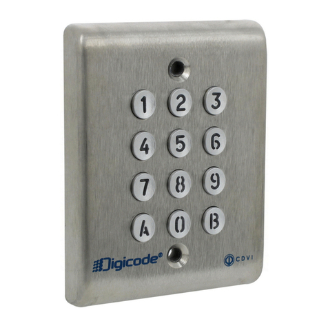
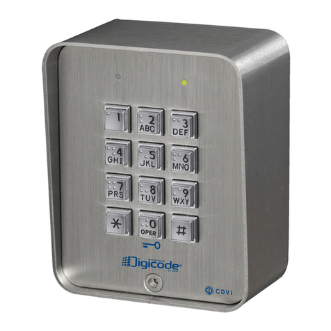
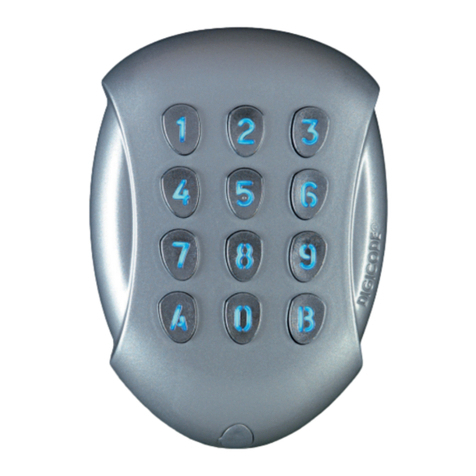
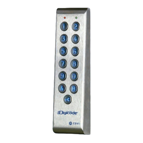
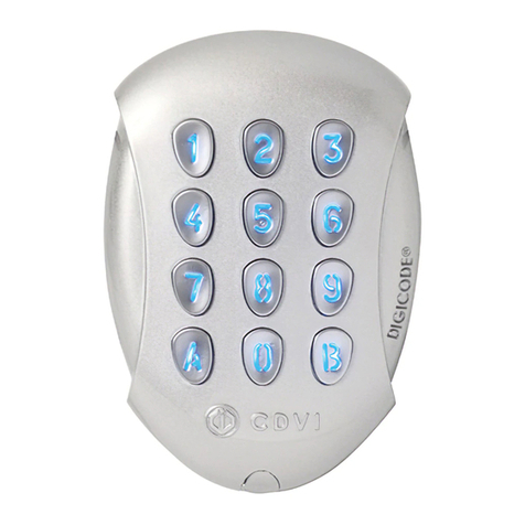
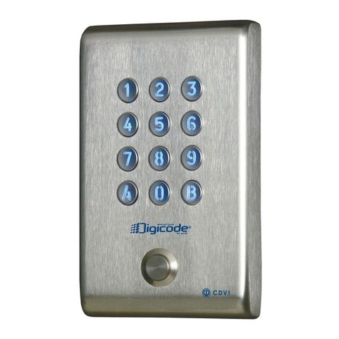
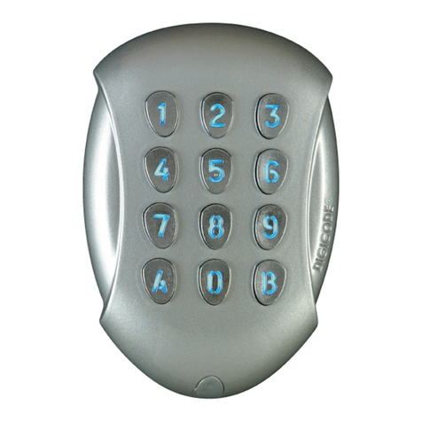
CDVI GALEO 4.0 - Bluetooth User manual

GALEO 4.0 - Bluetooth
BOXCODE
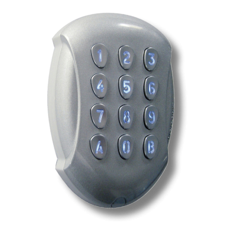
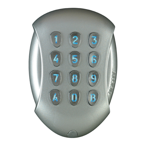
Teclado antivandálico con conectividad Bluetooth
Weatherproof Illuminated keypad with remote electronics
ESPAÑOL
ES
ENGLISH
EN
4.
Galeo
La elección del instalador
The installer’s choice

1] PRESENTACIÓN DE PRODUCTO
2
Gracias por depositar su conanza en CDVI con la adquisición de este producto.
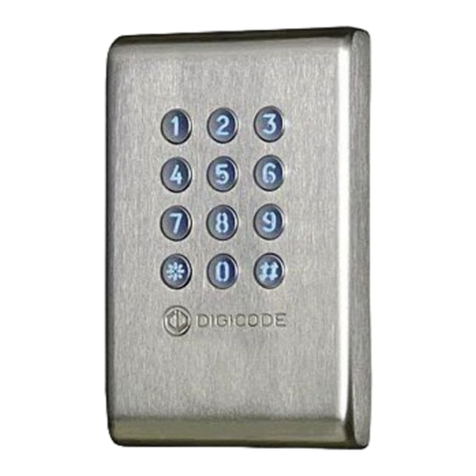
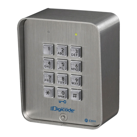
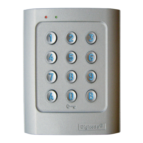
Teclado Digicode® para exterior - IP64 (botonera).
- Acabado en Zamak - Antivandálico.
Electrónica externa.
- Electrónica de control para ser instalada en un ambiente seguro y conectada a botonera
a través de un cable de 3 metros incluido.
Conexión Plug’n’play.
- Tensión libre: 12-24 Vca | 12-48 Vcc.
- 3 salidas de relé de cerradura (5A / 250 Vca).
Programación sencilla e intuitiva.
- Hasta 100 códigos de acceso con posibilidad de cambio por el propio usuario.
Diseño compacto.
Ergonómico.
- Señalización visual y sonora.
Programación por defecto.
- Sin código maestro (únicamente de 5 dígitos) o de acceso memorizados.
2 modos de funcionamiento.
- Funcionamiento del BOXCODE únicamente con las app de CDVI.
- Funcionamiento del BOXCODE con las app de CDVI y con la botonera del teclado.
ES
GALEO 4.0 Bluetooth
Teclado antivandálico con conectividad Bluetooth
MANUAL DE INSTALACIÓN
LA APLICACIÓN DE INSTALADOR
Tiene a su disposición una app de instalador con la que conectarse por Bluetooth al teclado y
así poder congurarlo y gestionar códigos y usuarios desde su smartphone. Esta aplicación ya
está disponible para Android (a partir de Android 5) e IOS (a partir de IOS 8.1).
6 pasos de programación:
1. Haga click en Boxes conectados
y seleccione el box correspondiente 3. Gestione códigos
para el relé 1
2. Cambie el
nombre del box
cdvigroup.com
Introduzca el código
maestro durante el primer
uso o conexión

cdvigroup.com
2] NOTAS Y RECOMENDACIONES
Recomendaciones de cableado:
La distancia entre el GALEO y la electrónica externa
no debe superar los 10 metros. Asegúrese de que
el cable no pasa junto a cables de alimentación o
alto voltaje (ejemplo: 230 Vca).
Cable recomendado entre el GALEO y la elec-
trónica externa:
Cable de 2 pares (4 hilos) SYT1 8/10º (AWG 20).
Fuentes de alimentación recomendadas:
ADC335 o BS60.
Recomendaciones de montaje:
Para evitar posibles acciones vandálicas ,
recomendamos instalar la botonera en supercies
planas.
Consejos de seguridad :
Por motivos de seguridad, no hay programado
ningún código maestro (5 dígitos).
El código 12345 no puede usarse como código
maestro.
Al programar un nuevo código maestro, evite usar
combinaciones sencillas(ejemplo: 34567).
Recomendaciones de instalación:
Para asegurar el sistema contra picos de tensión,
no olvide instalar un varistor en paralelo al
dispositivo de cierre utilizado.
La electrónica externa del GALEO debe estar insta-
lada obligatoriamente en lugares protegidos de la
intemperie.
3cdvigroup.com
75
110
15
ES
GALEO 4.0 Bluetooth
Teclado antivandálico con conectividad Bluetooth
MANUAL DE INSTALACIÓN
147
124
56
ELECTRÓNICA EXTERNA (BOXCODE)
Consumos
(3 relés activos y teclado
iluminado)
12V 24V 48V
CA 166 mA 82mA -
CC 195 mA 105 mA 54mA
5. Cree chas de
usuarios
4. Congure
las temporizaciones
6. Abra las puertas
con los botones
TMGALEO (OPCIONAL)
IP64
-25°C a +70°C
Test de vibraciones
Test de rociado de sal
IK10 -25°C a +70°C
IP52

4cdvigroup.com
ES
GALEO 4.0 Bluetooth
Teclado antivandálico con conectividad Bluetooth
MANUAL DE INSTALACIÓN
Varistor Tornillo Torx®
(M4x10)
Llave para
tornillo
Torx®(T20) Tapa Tornillo
(M4x30) Taco de
jación Pasacables Pasacables
Placa de
jación de
electrónica
externa
GALEO - 1 1 1 2 2 - - -
Electrónica
externa 1 - - - 2 2 2 2 1
3] KIT DE MONTAJE
4] INSTRUCCIONES DE MONTAJE
GALEO ®
GALEO ®
(x4)
1
GALEO ®
GALEO ®
(x4)
4
GALEO ®
GALEO ®
(x4)
2
GALEO ®
GALEO ®
(x4)
5
GALEO ®
GALEO ®
(x4)
3
GALEO ®
GALEO ®
(x4)
6
Compruebe la distancia entre el
GALEO y su electrónica externa. Co-
loque la placa de jación del GALEO
en la pared y el accesorio de jación
de la electrónica externa. Marque la
ubicación de los agujeros a taladrar
(Ø 5 mm y profundidad 35 mm), así
como la ubicación del agujero del
cableado que une botonera y elec-
trónica. Practique todos los taladros
necesarios.
Fije el GALEO en su ubicación con
el tornillo TORX®suministrado.
Ayúdese de la llave correspondiente
y ponga la tapa en la parte inferior
para cubrir el tornillo.
Coloque los dos tacos de jación y
je la placa de montaje del GALEO
en la pared sirviéndose de los
tornillos suministrados.
Coloque los dos tacos de jación, y
luego je la placa de montaje de la
electrónica externa con los tornillos
suministrados. Ponga la electrónica
externa sobre su soporte.
Pase el cable del GALEO por el
hueco correspondiente y coloque la
botonera sobre la placa de montaje,
comenzando a colocarla por la parte
superior.
Coloque los pasacables en la parte
inferior de la electrónica y pase
todos los hilos necesarios para
completar su instalación. No se
olvide de usar un varistor con cada
uno de los dispositivos de cierre.
Cerradura func. normal
Strike Fail Secure
Ventosa/Cerradura inv.
Magnet/Strike Fail Safe
Cerradura func. normal
Strike Fail Secure
Blanco / White
Marrón / Brown
Verde o azul / Green or Blue
BP1
PB1
BP2
PB2
P1P2
230 Vca
Alimentación
Input voltage
12/24 Vca
12/48 Vcc
Borne Correspondencia
Entrada V
Alimentación 12/24 Vca o 12/48 Vcc
V
Alimentación 12/24 Vca o 12/48 Vcc
Puerta 1
NC Contacto Normalmente Cerrado del relé 1
C Común del relé 1
NO Contacto Normalmente Abierto del relé 1
Puerta 2
NC Contacto Normalmente Cerrado del relé 2
C Común del relé 2
NO Contacto Normalmente Abierto del relé 2
Puerta 3
NC Contacto Normalmente Cerrado del relé 3
C Común del relé 3
NO Contacto Normalmente Abierto del relé 3
Pulsadores
de salida
PB1 Pulsador de salida del relé 1
M Común de pulsadores
PB2 Pulsador de salida del relé 2
Horario
PX No utilizado
H No utilizado
H Contacto horario
Digicode®
TMGALEO
+ Teclado - Hilo blanco
- Teclado - Hilo marrón
E Teclado - Hilo verde o azul (iluminación)
5] ESQUEMA DE CABLEADO - GALEO 3 RELÉS
Pulsadores de salida
El pulsador de salida PB1 actuará
sobre el relé 1, mientras que el
pulsador de salida PB2 actuará sobre
el relé 2. La temporización y modo de
funcionamiento son programables.
El contacto horario H permite usar
cualquier botón como pulsador de
entrada.
Si el contacto está abierto, las teclas se
usarán para introducir códigos de acceso.
Si el contacto está cerrado, la puerta se
desbloqueará al pulsar cualquier tecla.
Electrónica externa
El júmper P2 permite
a un usuario cambiar
su propio código de
acceso. Ponga el
júmper para activar
esta función (acuda
al apartado corres-
pondiente para más
información).
El júmper P1 devuelve
el teclado a valores de
inicio. Corte la alimenta-
ción antes de colocar el
júmper (acuda al apartado
correspondiente para más
información).
5cdvigroup.com
ES
GALEO 4.0 Bluetooth
Teclado antivandálico con conectividad Bluetooth
MANUAL DE INSTALACIÓN

6] ESQUEMA DE PROGRAMACIÓN
Teclee 2 veces el
código maestro
2 pitidos
1 pitido
1 pitido = OK
(4 pitidos = Error)
10-99 segundos
00 = continuo
10 = Defecto
A0
Temporización de
iluminación de
teclado
1 pitido
1 pitido = OK
(4 pitidos = Error)
01-99 segundos
00 = biestable
01 = Defecto
A2
Temporización del
relé 2
1 pitido
1 pitido = OK
(4 pitidos = Error)
01-99 segundos
00 = biestable
01 = Defecto
A1
Temporización del
relé 1
1 pitido
1 pitido = OK
(4 pitidos = Error)
01-99 segundos
00 = biestable
01 = Defecto
A3
Temporización del
relé 3
1 pitido
1 pitido = OK
(4 pitidos = Error)
4 o 5
5 = Defecto
A4
Número de dígitos
de los códigos
1 pitido
1 pitido = OK
(4 pitidos = Error)
Todos los botones
son válidos
12345=
prohibido
A5
Código maestro
6cdvigroup.com
ES
GALEO 4.0 Bluetooth
Teclado antivandálico con conectividad Bluetooth
MANUAL DE INSTALACIÓN
GALEO 3 Relés
Relé 1 : Códigos memorizados en posiciones de la 00 a la 59.
Relé 2: Códigos memorizados en posiciones de la 60 a la 79.
Relé 3: Códigos memorizados en posiciones de la 80 a la 99.
RECORDATORIO
Para más información, acudir a la página 8.

2 pitidos
1 pitido
A6
Reset a valores de
inicio
1 pitido
1 pitido = OK
(4 pitidos = Error)
2
dígitos
AB=Defecto
A7
Código para cambio
de códigos por el
usuario - Relé 1
1 pitido
1 pitido = OK
(4 pitidos = Error)
2
dígitos
13=Defecto
A8
Código para cambio
de códigos por el
usuario - Relé 2
1 pitido
1 pitido = OK
(4 pitidos = Error)
2
dígitos
46=Defecto
A9
Código para cambio
de códigos por el
usuario - Relé 3
1 pitido
1 pitido = OK
(4 pitidos = Error)
0 = Desactivar
pitidos
1 = Activar pitidos
AA
Señalización
sonora
1 pitido = OK
4 o 5 dígitos
------------------
4 pitidos =
Pos. de memoria
ocupada
00-99
Programación de
códigos de usuario
B
A
7cdvigroup.com
ES
GALEO 4.0 Bluetooth
Teclado antivandálico con conectividad Bluetooth
MANUAL DE INSTALACIÓN
B

ES
GALEO 4.0 Bluetooth
Teclado antivandálico con conectividad Bluetooth
MANUAL DE INSTALACIÓN
7] PROGRAMACIÓN
8cdvigroup.com
A. PRIMER USO O DESPUÉS DE RESET A VALORES DE INICIO
1. Alimente el sistema:
En la electrónica externa:
- El LED verde se enciende.
- Después, el LED rojo se enciende.
- Después, los LED verde y rojo parpadean.
En el teclado:
- Se emite 1 pitido.
- El teclado se ilumina y parpadea.
2. Teclee 2 veces un mismo código para guardarlo como código maestro (sólo 5 dígitos).
El código 12345 no está permitido como código maestro.
- El teclado deja de parpadear.
- Después de introducir una vez el código, el teclado parpadea una vez.
- Teclee una segunda vez el código maestro.
- Si los códigos introducidos coinciden, se emitirán 2 pitidos.
Si no fuera así, espere a que el teclado vuelva a parpadear antes de volver a introducir 2
veces el código maestro (aproximadamente 10 segundos).
- Entrará en modo de programación.
3. Congure el sistema según indica el diagrama de programación.
- Para salir del modo de programación, pulse la tecla B. Escuchará 2 pitidos.
B. RESET DE LA MEMORIA
Puede entrar en modo de programación y seleccionar la opción A6, aunque también hay una
segunda posibilidad:
1. Corte la alimentación del teclado y ponga el júmper P1 (consulte la página 5).
2. Devuelva la alimentación al teclado:
En la electrónica externa:
- El LED rojo queda encendido jamente durante el reset a valores de inicio.
- Después del reset, los LED rojo y verde parpadean a la espera de introducir un nuevo
código maestro.
En el teclado:
- Se emiten 6 pitidos cortos durante el reset, y al nal, se emitirá un pitido largo.
- El teclado se ilumina y parpadea a la espera de introducir un nuevo código maestro.

ES
GALEO 4.0 Bluetooth
Teclado antivandálico con conectividad Bluetooth
MANUAL DE INSTALACIÓN
3. Quite el júmper P1.
- El código maestro y los códigos de acceso han sido borrados y se ha vuelto a valores de
inicio.
4. Empiece el proceso de programación desde el paso A.
C. RESET DEL CÓDIGO MAESTRO
Con el teclado en funcionamiento normal, coloque el júmper P1. Espere a que el teclado
empiece a parpadear para introducir un nuevo código maestro.
En la electrónica externa:
- El LED rojo se ilumina jamente durante el reset del código maestro.
- Después, el LED verde se ilumina.
En el teclado:
- Se emiten 3 pitidos cortos durante el reset del código maestro, y después, se emite un
pitido largo.
- El teclado se ilumina y empieza a parpadear a la espera de un nuevo código
maestro.
D. CAMBIO DE UN CÓDIGO DE ACCESO POR EL PROPIO USUARIO
Para autorizar a un usuario a cambiar su propio código de acceso, hay que dejar puesto el
júmper P2. Para desactivar esta función, basta con quitar este júmper.
1. Introduzca el código de acceso que se está utilizando actualmente.
- El relé de cerradura de activa y se emite un pitido.
2. Teclee inmediatamente los dos dígitos correspondientes a su código de modicación:
- Relé 1 (por defecto): A y B
- Relé 2 (por defecto): 1 y 3.
- Relé 3 (por defecto): 4 y 6.
- Se emitirá un pitido para autorizar la modicación.
3. Teclee el nuevo código de apertura.
- Se emitirán 2 pitidos para conrmar la memorización del nuevo código. El teclado volverá al
modo stand-by.
4. Compruebe que el nuevo código funciona correctamente.
9cdvigroup.com

Digicode® indoor/outdoor - IP64 (keypad)
- Polished heavy duty Zamak®cast alloy, high resistance to vandalism
Remote controller
- remote controller and intelligence in a protected environment and connected with 3m cable
Plug’n’play connection
- Free voltage
- 12V to 24Vac and 12V to 48Vdc
- 3 independent relay outputs
Intuitive programming
- 100 user codes customisable by each user
Ergonomic
- Audible and visual feedback
Default programming
There is no master code in the factory setting (only 5 terms)
2 mounting available
- Operation of the BOXCODE perform with CDVI App
- Operation of the BOXCODE with CDVI App or TMGALEO keypad
1] KEY FEATURES
Thank you for buying our products and for the condence you placed
in our company.
EN
GALEO 4.0 Bluetooth
Weatherproof Illuminated Keypad with remote electronics
INSTALLATION MANUAL
10 cdvigroup.com
THE APPLICATION
You have a possibility to add users with the Bluetooth connection and your Smartphone.
This app is available from Android 5 and IOS 8.1
6 steps about programming :
1. Press
connected box
3. Change user
codes relay 1
(door)
2. Change the box
name
enter the master code
during the rst use
or connection

2] NOTES & RECOMMENDATIONS
Cable :
The distance between the GALEO and the remote
electronic can not exceed more than 10 meters.
Make sure that the cable is not near by a high
voltage cables (ex: 230 V AC).
Recommended cable between the GALEO
and the remote electronic :
To expand the supplied 3 meter cable, select a 2
twisted pairs cable (4 wires), SYT1 0.8MM (AWG 20).
Recommended power supplies suitable
for the GALEO :
ADC335 (230V input) or BS60 (230V input).
Mounting recommendations :
Mount the keypad on a at surface to avoid any
vandalism and to insure the best mounting.
Security advice :
For security advice reasons, there is no master
code in the factory setting (only 5 terms).
The 1 2 3 4 5 code is forbidden as a master code.
When selecting a master code and user code avoid
sequencial codes (example : 3 4 5 6 7).
Back EMF protection :
To secure the system from back electromagnetic
elds do not forget to mount the varistor in parallel
on the lock.
EN
GALEO 4.0 Bluetooth
Weatherproof Illuminated Keypad with remote electronics
INSTALLATION MANUAL
147
124
56
75
110
15
REMOTE CONTROLLER (BOXCODE)
Consumption
(3 relay outputs activated and
keypad illuminated)
12V 24V 48V
AC 166mA 82 mA -
DC 195mA 105 mA 54mA
TMGALEO (OPTIONAL)
5. Create
user sheet
4. Unlock time
conguration
6. Open the door
with the button
11cdvigroup.com
IP64
-25°C to +70°C
Vibrations tests
Salt spray
IK10 -25°C to +70°C
IP52

12 cdvigroup.com
EN
GALEO 4.0 Bluetooth
Weatherproof Illuminated Keypad with remote electronics
INSTALLATION MANUAL
3] MOUNTING KIT
4] MOUNTING
GALEO ®
GALEO ®
(x4)
1
GALEO ®
GALEO ®
(x4)
4
GALEO ®
GALEO ®
(x4)
2
GALEO ®
GALEO ®
(x4)
5
GALEO ®
GALEO ®
(x4)
3
GALEO ®
GALEO ®
(x4)
6
Verify the distance between the
GALEO keypad and its remote
electronic (Refer to page 3 «Notes and
Recommendations»). Place the back
plate of the GALEO on the wall and
the bracket of the remote electronic
then mark with a pen the hole location
then drill the 2 mounting holes (drill bit
Ø 5 mm and 35 mm hole depth)
and the hole wiring access.
Fasten the GALEO keypad to the back
plate by using the supplied (M4x10)
Torx®screw and T20 Trox spanner
hardware. Place the screw cap at the
bottom of the keypad.
Insert the 2 plastic anchors in the
holes. Place the back plate of the
GALEO and screw on the wall using
the supplied (M4x30) mounting
screws.
Insert the 2 plastic anchors in the holes.
Place the bracket of the electronic
and screw on the wall using the supplied
M4x30 screws. Slide the box from up
to down on the bracket.
Insert the cable in the hole access
area of the back plate. Then mount
the keypad on the back plate,
placing rst the top in the hooks
and then the bottom.
Insert the cable in the remote electronic
and wire the cable to the terminals.
Do not forget to install the varistor
on the lock (Refer to page 3 «Notes
and Recommendations»).
Varistor (M4x10)
Torx®
screw
T20 Torx®
Spanner Caps (M4x30)
mounting
screws
Plastic
anchors
Wiring
sealed
cap
Wiring
sealed
cap
Mounting
plate for
remote
electronic
box
GALEO - 1 1 1 2 2 - - -
Remote
Controller 1 - - - 2 2 2 2 1

Cerradura func. normal
Strike Fail Secure
Ventosa/Cerradura inv.
Magnet/Strike Fail Safe
Cerradura func. normal
Strike Fail Secure
Blanco / White
Marrón / Brown
Verde o azul / Green or Blue
BP1
PB1
BP2
PB2
P1P2
230 Vca
Alimentación
Input voltage
12/24 Vca
12/48 Vcc
5] WIRING DIAGRAM GALEO 3 RELAY OUTPUTS
13
cdvigroup.com
EN
GALEO 4.0 Bluetooth
Weatherproof Illuminated Keypad with remote electronics
INSTALLATION MANUAL
Remote electronics
P2 jumper allows
to the user to modify
its own Pin code.
To enable this feature put
the jumper on.
P1 jumper resets the
keypad to factory default
values. Remove the power
from the keypad then put
the jumper.
PB1 request-to-exit input activates relay 1.
PB2 request-to-exit input activates relay 2.
Latch or toggled output.
Hinput can be used with a timer to enable
free access by pressing on any digit key on
the keypad.
When the contact is open
then the request-to-enter is disabled.
When the contact is closed then press any
key on the keypad to enter.
Outputs Wiring table
INPUT
V
Input voltage 12V to 24VAC or 12V to 48VDC
V
Input voltage 12V to 24VAC or 12V to 48VDC
DOOR 1
NC N/C contact relay 1
CCommon relay 1
NO N/O contact relay 1
DOOR 2
NC N/C contact relay 2
CCommon relay 2
NO N/O contact relay 2
DOOR 3
NC N/C contact relay 3
CCommon relay 3
NO N/O contact relay 3
Push
button
PB1 Request-to-exit input relay 1
MCommon of inputs
PB2 Request-to-exit input relay 2
Clock
PX Not used
HNot used
HTimer Contact
Keypad
TMGALEO
+ White wire from keypad
-Brown wire from keypad
EGreen or Blue wire (illumination)

14 cdvigroup.com
6] PROGRAMMING CHART
Enter Master
code twice
2 x beeps
1 x beep
1 x beep = OK
4 beeps = Error
10-99 sec
00 = permanent
10=Default
A0
Illumination
duration
1 x beep
1 x beep = OK
4 beeps = Error
01-99 sec
00 = toggled
01=Default
A2
Time Relay 2
1 x beep
1 x beep = OK
4 beeps = Error
01-99 sec
00 = toggled
01=Default
A1
Time Relay 1
1 x beep
1 x beep = OK
4 beeps = Error
01-99 sec
00 = toggled
01=Default
A3
Time Relay 3
1 x beep
1 x beep = OK
4 beeps = Error
4’ or 5’
digits
5=Default
A4
Code length
1 x beep
1 x beep = OK
4 beeps = Error
Change master
code
12345=prohibited
A5
Master code
EN
GALEO 4.0 Bluetooth
Weatherproof Illuminated Keypad with remote electronics
INSTALLATION MANUAL
GALEO Relays 3 (3 outputs)
Relay 1 : From 00 to 59,
Relay 2 : From 60 to 79,
Relay 3 : From 80 to 99.
REMINDER
Find the additional informations page 16.

15cdvigroup.com
2 x beeps
1 x beep
A6
Reset
1 x beep
1 x beep = OK
4 beeps = Error
2
digits
AB=default
A7
Sub master code 1
1 x beep
1 x beep = OK
4 beeps = Error
2
digits
13=default
A8
Sub master code 2
1 x beep
1 x beep = OK
4 beeps = Error
2
digits
46=default
A9
Sub master code 3
1 x beep
1 x beep = OK
4 beeps = Error
0= Buzzer disabled
1 = Buzzer
enabled
AA
Buzzer
(Audible feedback)
1 x beep = OK
4’ or 5’ digit code
------------------
4 beeps = User
location: “used”
00-99
User codes
B
A
EN
GALEO 4.0 Bluetooth
Weatherproof Illuminated Keypad with remote electronics
INSTALLATION MANUAL
B
Find the additional informations page 16.

7] PROGRAMMING
16 cdvigroup.com
A. FIRST USE OR AFTER RESET
1. Power up the system
On the remote electronics:
- Green LED lights on
- Then the Red LED lights on
- Then the Red and Green LED ash
On the keypad:
- 1 beep is emitted
- The keypad lights on and ashes
2. Enter a new code twice for the master code (only 5 terms).
The 12345 code is forbidden in master code.
- The keypad stop ashing
- After the rst entry of the master code, the keypad ashes 1 time
- Enter the second entry of the master code
- If both entry of the master code are the same, 2 beeps are emitted.
Otherwise, wait until the keypad ashes again to enter the new master code twice
(about 10 seconds)
- Entry in programming mode
3. Congure the system with the programming chart
- Press B to exit from programming mode
B. RESET MEMORY
1. Cut off the power and put the jumper on P.
- Refer to page 13 for the jumper P1 on the remote electronics
2. Put the power back :
On the remote electronics:
- Red LED lights on during reset
- After the reset, Red and Green LEDs still ashing while waiting new master code
On the Keypad:
- 6 short beeps are emitted during reset and at the end 1 long beep is emitted
- The keypad still ashing while waiting new master code
3. Pull out the jumper on P1
- Master code and user codes are cleared and set to default value
4. Start again from part A
EN
GALEO 4.0 Bluetooth
Weatherproof Illuminated Keypad with remote electronics
INSTALLATION MANUAL

C. RESET MASTER CODE
On stand-by operating mode, put a jumper on P1. Wait until the keypad ashes to enter new
master code.
On the remote electronics:
- Red LED lights on during the reset of the master code
- Then Green LED lights on
On the keypad:
- 3 short beeps are emitting during the reset of the master code and after that
1 long beep is emitted
- The keypad ashes while waiting the entry of a new master code
D. CHANGING THE CODE BY A USER
To authorize a user to modify its own user code, put a jumper on P2 (to disable the feature,
remove the jumper)
1. Enter the current user code
- The relay is activated and a beep is emitted
2. Enter the 2 digits sub master code
- Relay 1, default sub master code: A and B
- Relay 2, default sub master code: 1 and 3
- Relay 3, default sub master code: 4 and 6
- A beep is emitted to authorize the modication
3. Enter the new user code
- 2 beeps are emitted to conrm the new code
4. Check the new user code to be sure of the modication
17cdvigroup.com
EN
GALEO 4.0 Bluetooth
Weatherproof Illuminated Keypad with remote electronics
INSTALLATION MANUAL

18 cdvigroup.com
NOTAS / NOTES
EN
GALEO 4.0 Bluetooth
Weatherproof Illuminated Keypad with remote electronics
INSTALLATION MANUAL

19cdvigroup.com
Esta tabla le ayudará a llevar un registro de todos los códigos de usuario que tenga guardados.
To program pin codes.
Pos.
User Código / Code Nombre
Name
00
01
02
03
04
05
06
07
08
09
10
11
12
13
14
15
16
17
18
19
20
21
22
23
24
25
26
27
28
29
30
31
32
33
Pos.
User Código / Code Nombre
Name
34
35
36
37
38
39
40
41
42
43
44
45
46
47
48
49
50
51
52
53
54
55
56
57
58
59
60
61
62
63
64
65
66
67
Pos.
User Código / Code Nombre
Name
68
69
70
71
72
73
74
75
76
77
78
79
80
81
82
83
84
85
86
87
88
89
90
91
92
93
94
95
96
97
98
99
GALEO 3 Relés
Relé 1 : Posiciones 00 a 59.
Relé 2 : Posiciones 60 a 79.
Relé 3 : Posiciones 80 a 99.
GALEO 3 Relays
Relay 1 : From 00 to 59.
Relay 2 : From 60 to 79.
Relay 3 : From 80 to 99.
RECORDATORIO
REMINDER
19cdvigroup.com
EN
GALEO 4.0 Bluetooth
Weatherproof Illuminated Keypad with remote electronics
INSTALLATION MANUAL

Referencia :
Extranet :
CDVI Group
FRANCE (Siège social/Headquarter)
Phone: +33 (0)1 48 91 01 02
CDVI SAS
FRANCE + EXPORT
31, av. du Général Leclerc
93500 PANTIN - France
Phone: +33 (0)1 48 91 01 02
www.cdvi.com
CDVI AMERICAS
[CANADA - USA]
Phone: +1 (450) 682 7945
www.cdvi.ca
CDVI BENELUX
[BELGIUM - NETHERLAND - LUXEMBOURG]
Phone: +32 (0) 56 73 93 00
www.cdvibenelux.com
CDVI TAIWAN
Phone: +886 (0)42471 2188
www.cdvichina.cn
CDVI SUISSE
Phone: +41 (0)21 882 18 41
www.cdvi.ch
CDVI CHINA
Phone: +86 (0)10 84606132/82
www.cdvichina.cn
CDVI IBÉRICA
[SPAIN - PORTUGAL]
Phone: +34 (0)935 390 966
www.cdviberica.com
CDVI ITALIA
Phone: +39 0321 90 573
Fax: +39 0321 90 8018
www.cdvi.it
CDVI MAROC
Phone: +212 (0)5 22 48 09 40
www.cdvi.ma
CDVI SWEDEN
[SWEDEN - DENMARK - NORWAY - FINLAND]
Phone: +46 (0)31 760 19 30
www.cdvi.se
CDVI UK
[UNITED KINGDOM - IRELAND]
Phone: +44 (0)1628 531300
www.cdvi.co.uk
All the information contained within this document (pictures, drawing, features, specications and dimensions)
could be perceptibly different and can be changed without prior notice.
Toda la información mostrada en este documento (diagramas, dibujos, funcionalidades, especicaciones y dimensiones)
pueden ser diferentes y pueden cambiar sin previo aviso.
La elección del instalador
The installer’s choice
Other manuals for GALEO 4.0 - Bluetooth
3
Table of contents
Languages:
Other CDVI Keypad manuals

CDVI
CDVI DGA User manual

CDVI
CDVI GALEOR User manual

CDVI
CDVI GALEO 4.0 - Bluetooth User manual

CDVI
CDVI CAASE User manual

CDVI
CDVI Digicode Series User manual

CDVI
CDVI KCIEN User manual

CDVI
CDVI SUBLIM User manual

CDVI
CDVI Digicode DGA User manual

CDVI
CDVI KCINBT User manual

CDVI
CDVI Digicode Series User manual
Popular Keypad manuals by other brands

CAMDEN
CAMDEN CM-110SK installation instructions

UTC Fire and Security
UTC Fire and Security interlogix ATS1135 Installation sheet

Honeywell
Honeywell 6150 - Ademco Fixed - Display Keypad Installation and setup guide

Kaba
Kaba Keyscan WSSKP-1 Installation & programming guide

Satel
Satel INT-TSG2 user manual

Bosch
Bosch D621 Series installation guide