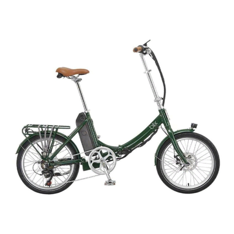
Blix Aveny User manual

Aveny
Assembly Guide


4
Aveny Assembly Guide
About this Guide
Package Contents
Welcome to the assembly guide for your Blix
Aveny. We cra our bikes with an innovative and
user-friendly design, and the assembly guide is
no dierent. We’ve broken down each step so it’s
easy to follow whether you’re a seasoned pro or an
adventure-bound beginner.
A detailed assembly video is also available on mobile
and desktop at support.blixbike.com. Navigate to
the Maintenance & Use tab and scroll down to Bike
Assembly Instructions. And, of course, if you run into
any issues along the way our experienced support
team is always here to help.
Tip: We recommend consulting Blix Suppo to
assist in the assembly, service, and maintenance
of your bike.
• The Aveny
• Front Wheel & Fender
• Accessories & Small
Parts
- Right & Le Pedals
- Battery & Charger
- Keys
- Front Light
- Quick release
skewer and 2
small springs
• Tool Kit (listed from
smallest to largest)
- 3mm allen wrench
- 4mm allen wrench
- 5mm allen wrench
- 6mm allen wrench
- 8/10mm crescent
wrench
- 13/15mm crescent
wrench

5
Step 1: Unpacking your Blix
Step 2: Handlebars
Remove your bike from the box and set it on a
smooth, flat suace. Remove all of the packaging
material from the bike and carefully cut the zip-ties.
Note: We recommend keeping the box and
protective packaging for 30 days aer receiving
your bike in case any issues arise.
Assembly
1. Insert the stem into the fork.
2. Align the center of the handlebars with the center
of the fork.
3. When the stem and fork are pointing forward in
alignment, tighten down the stem bolt.

6
3. Remove the fender bolts from the fork crown and
the fender eyelets.
4. Using the bolts removed from the fork, attach the
fender.
1. Route the light cable through the hole at the top
of the front fender.
2. Secure the light cable through the clamps on the
inside, and pull the cable through the hole at the
front of the fender.
Step 3: Front Fender
Tip: Ensure the cable is securely fastened close to
the fender to prevent it from wearing down with
contact from the tire.
Assembly

7
1. Install the light on the attachment at the front of
the fender using the bolt and 4mm allen wrench.
Use the 8mm crescent wrench to keep tension.
2. Connect the light cables to the included front
light. The red cable connects to the positive [+]
terminal, and the black cable connects to the
negative [-] terminal.
Step 4: Lights
Assembly
Step 5: Front Wheel & Quick Release
1. Remove both wheel protectors from the axle of
the front wheel.
2. Remove the cap and one of the two springs from
the quick release skewer.

8
3. Push the quick release skewer through the axle of
the front wheel from the side opposite the brake
rotor disc.
4. Add the spring, with the small end of the spring
facing the bike, and the larger side of the spring
resting against the cap.
5. Install the cap, leaving just enough space for the
fork dropouts to be inserted.
6. Remove the plastic fork spacer from the fork.
7. Install the front wheel so that it is fully seated in
the front fork dropouts, and the brake rotor disc
slides into the brake caliper.
Tip: If you’re having trouble getting your front wheel
on, check to see that the brake cable is loose
enough.
Assembly

9
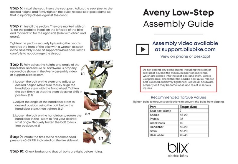
Step 6: Pedals
8. With the quick release lever open, tighten the cap,
then clamp down the quick release arm to firmly
attach the wheel to the dropouts. You should feel
firm resistance when closing the lever.
1. The pedals are marked with an “L” for le and an
“R” for right on the end of the axle. The right pedal
should be installed on the side with the chain and
gears.
2. Start by hand-threading each pedal onto the bike.
Then, tighten the pedals securely using the 15mm
crescent wrench.
Note: The le pedal is reverse-threaded and
tightens in the opposite direction. Ensure pedals
thread correctly before tightening to prevent
damage.
Assembly

10
Step 7: Seat Adjustment
To adjust the seat height, open the quick
release seat post clamp. Once you’ve
reached your desired height, simply
clamp the quick release back down so
it squarely closes against the collar. If
the seat height continues to slip when
pressure is applied, you can tighten the
nut on the quick release clamp by hand.
To adjust the height of the stem, loosen the stem
bolt. Ensure the stem is fully aligned to the front
wheel before tightening the bolt back down.
To adjust the angle of the stem, loosen the bolt
at the bottom of the stem. Ensure the bolt is tight
once you’ve reached your desired angle.
To adjust the angle of the handlebar, loosen the
handlebar clamp. Ensure both bolts are tight once
you have reached your desired wrist angle.
There are three adjustments you can make to the handlebar
position: height, stem angle, and wrist-angle. Aer adjusting
the handlebars, you should be able to sit up straight without
needing to hold your arms or wrists in an uncomfortable
position.
Step 8: Handlebar Adjustment
Tip:You should be able to comfoably touch the
ground with your toes, and should be able to fully
extend your legs while pedaling. This is the optimal
height for your seat, but choose the height that
works best for you.
Follow the steps below to personalize your Aveny and
to check for safety.
Adjustment

11
Step 9: Tire Inflation
Step 10: Checking Brakes
Ensure your tires are inflated to the recommended
PSI. The PSI is written on the side of the tire for easy
reference. A properly inflated tire has lower rolling
resistance.
Your bike is now fully assembled. See the Blix
Owner’s Manual for tips and instructions on
getting the most out of your new Blix.
Ensure your brakes are adjusted properly by
checking that your brake levers stop before touching
the handlebars. Double-check that the wheel stops
spinning when the brakes are depressed.
Note: Inflating your tire at a lower than
recommended pressure may cause tires to become
flat.
Note: Our Brake Adjustment guide can be found
at suppo.blixbike.com, but we recommend
contacting an experienced bike mechanic for any
major adjustments to the brakes.
Adjustment
Tip: Before riding your Blix for the first time, double
check that all of the hardware on your bike is
secured properly to avoid components coming
loose which could result in serious injuries.

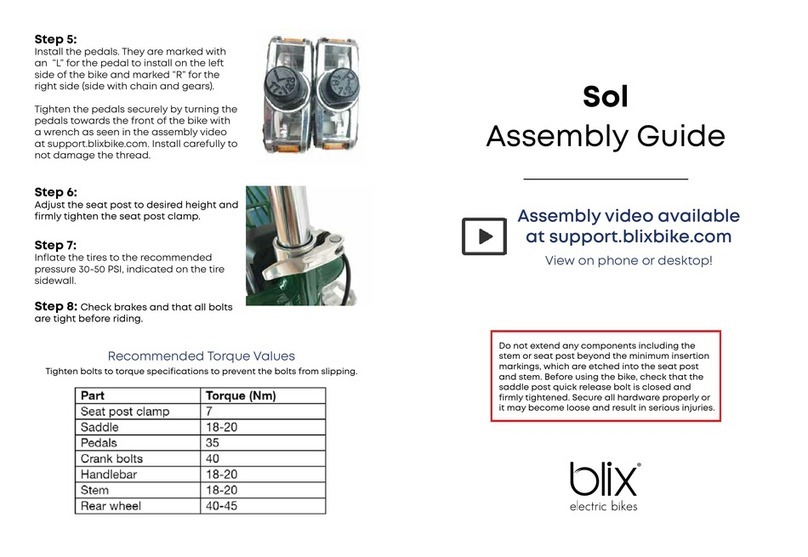
Recommended Torque Values
Tighten bolts to torque specifications to prevent the
bolts from slipping.
Part Torque (Nm)
Seat Post Clamp 7
Saddle 18-20
Pedals 35
Crank Bolts 40
Handlebar 18-20
Stem 18-20
Rear Wheel 40-45
https://support.blixbike.com/
support@blixbike.com
(855) 655-BLIX [2549]
blixbike.com
In Need of Support?
Table of contents
Other Blix Bicycle manuals

