Blu SPORT 4.5 User manual

BLU SPORT 4.5
SERVICE MANUAL

Contents
Contents ................................................................................................................................. 2
1. Introduction......................................................................................................................... 3
1.1 Objective ....................................................................................................................... 3
1.2 General Safety notice .................................................................................................... 3
1.3 Use Instruction .............................................................................................................. 3
2. Technology summarize ...................................................................................................... 4
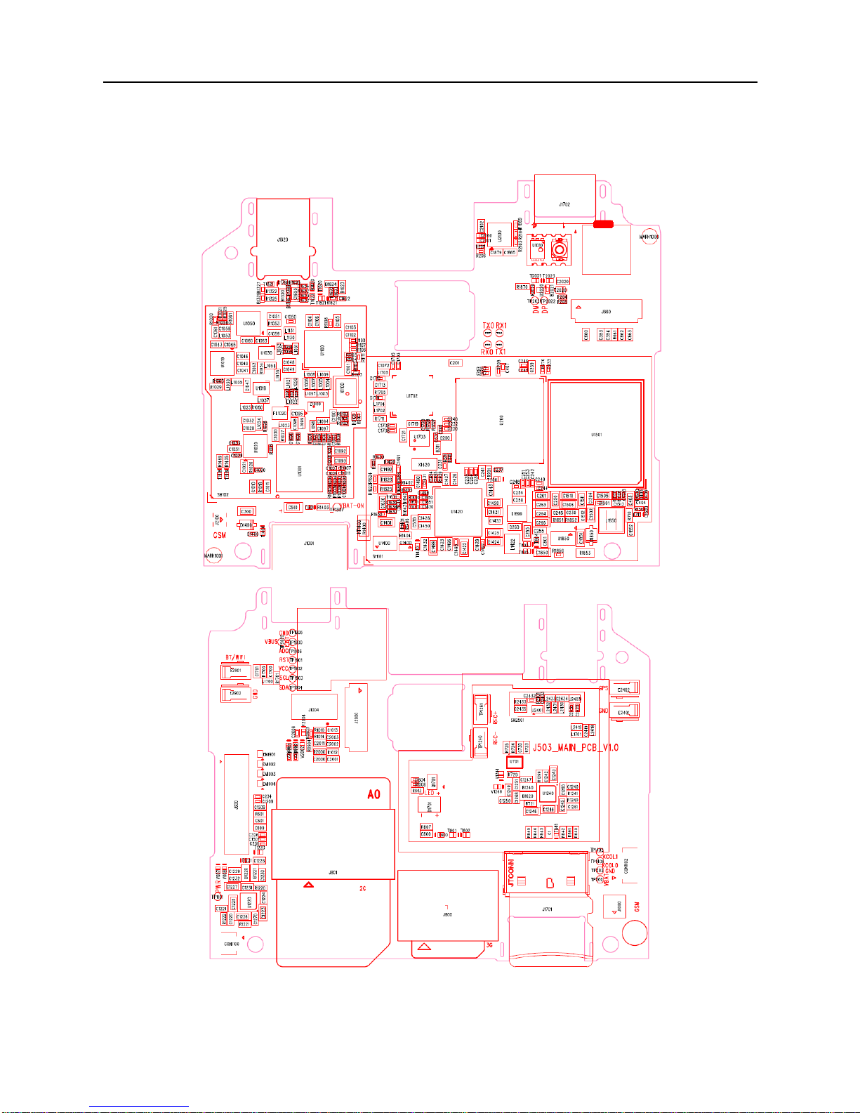
2.1 Description of main board component map ................................................................... 4
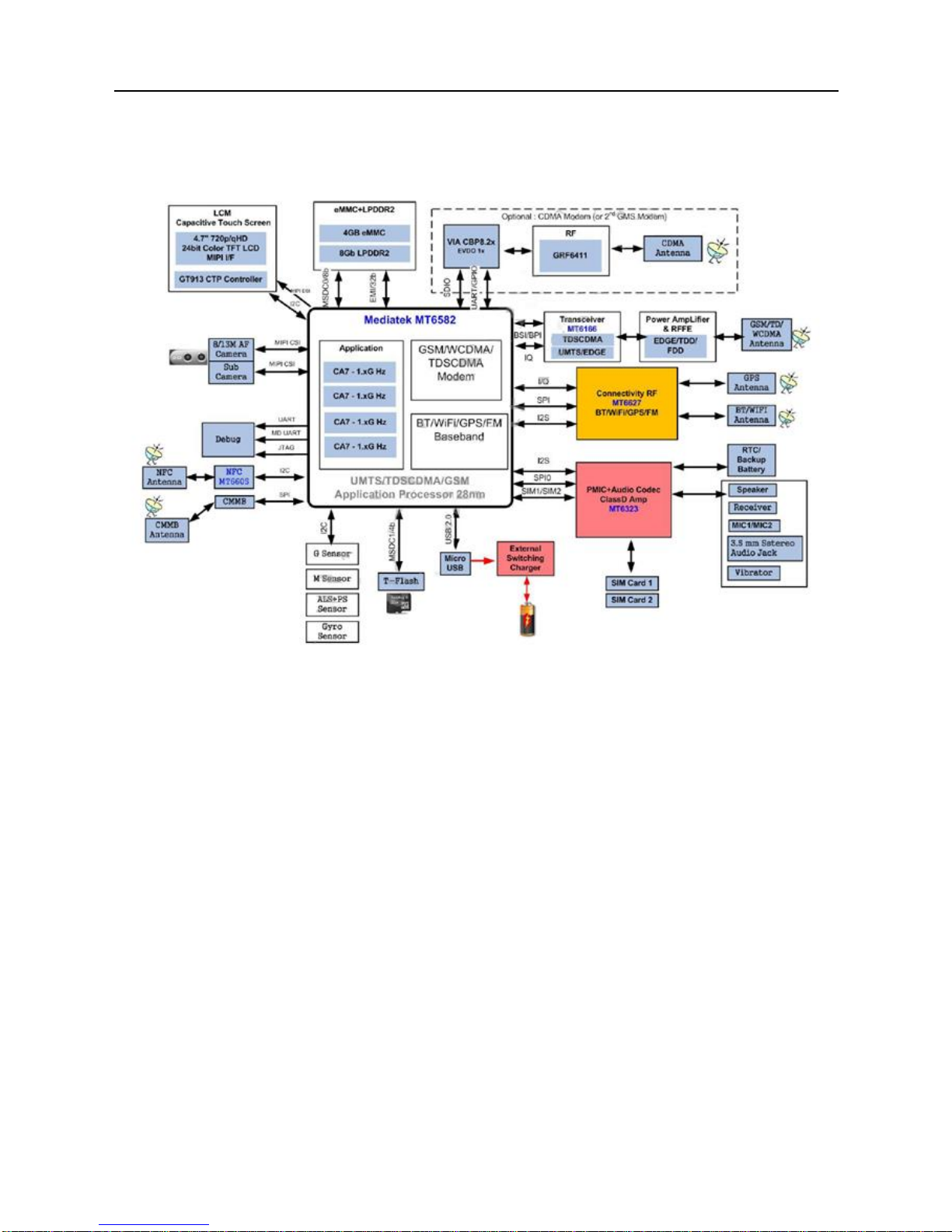
2.2 MT6582 circuit system................................................................................................... 5
2.3 Base band circuit........................................................................................................... 6
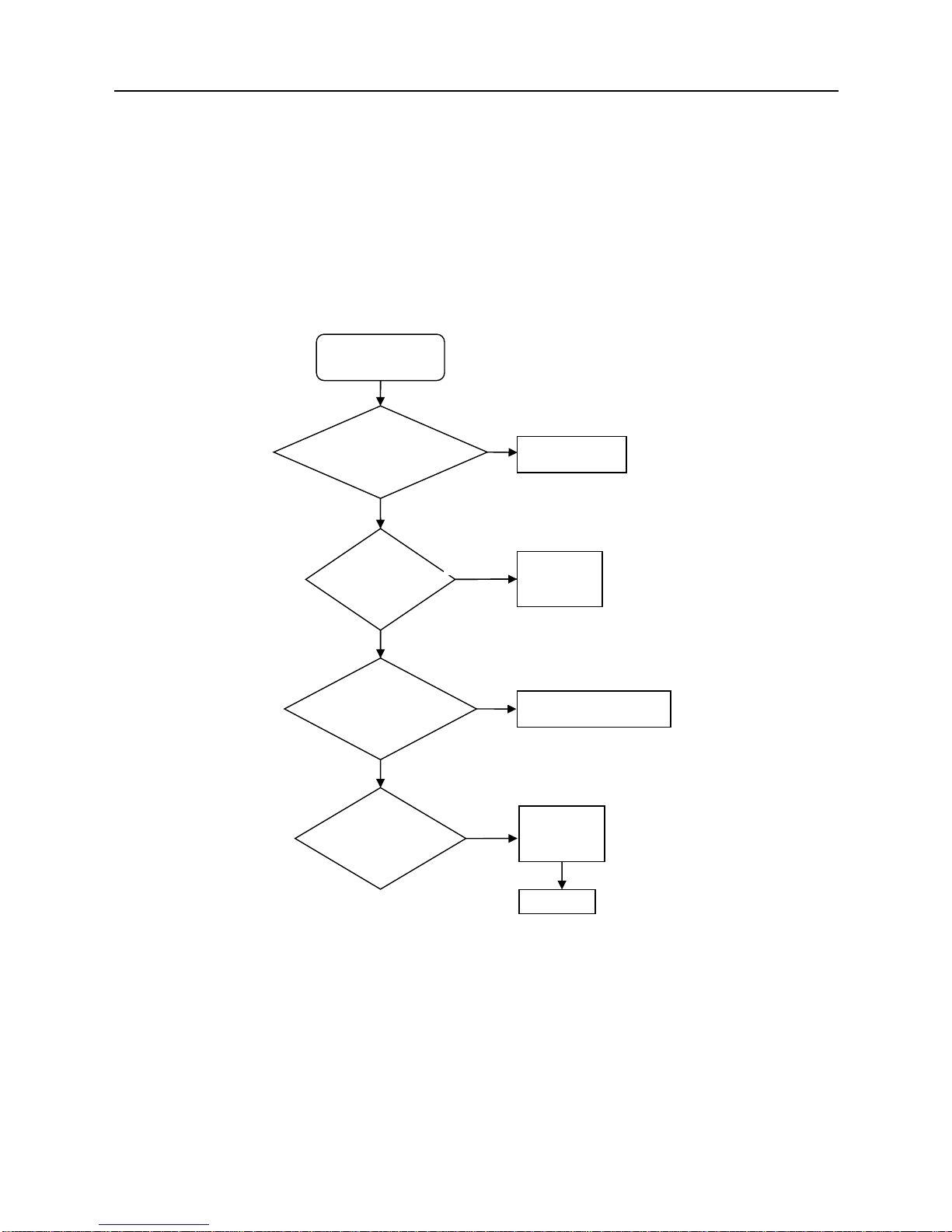
3. Trouble Shooting ................................................................................................................ 8
3.1 Fail to startup/power on ................................................................................................. 8
3.2 Fail to charge................................................................................................................. 9
3.3 Fail to display .............................................................................................................. 10
3.4 Fail to call .................................................................................................................... 11
3.5 Speaker no sound ....................................................................................................... 12
3.6 Earphone fail ............................................................................................................... 13
3.7 Vibrator fail .................................................................................................................. 14
3.8 Side key fail ................................................................................................................. 14
3.9 Failure to identify SIM card.......................................................................................... 15
3.10 Failure to write IMEI................................................................................................... 15
3.11 Camera fail ................................................................................................................ 16
3.12 Failure to read T-flash card ....................................................................................... 17
4. BGA related GND or no function pad ............................................................................... 18
4.1 CPU and memory pin map .......................................................................................... 18
4.2 PMU pin map............................................................................................................... 18

1. Introduction
1.1 Objective
The manual is not a general publication but only edited for experienced technician. The
main purpose is to provide basic foundation for the electrical & mechanical maintenance.
1.2 General Safety notice
1) Only experienced technician can repair with this guide during product is power on.Any
maintenance by other non-technicians will cause serious damage of the handset. Neither
short circuit nor counter-polarity connection is allowed for any electronic part in the
handset.
3) Be careful of ESD protection during maintenance to avoid the damage of electrostatic
sensitive components on the handset.
4) If disassembling operation is necessary for repairing, comply with mechanical structure
disassembling work instruction. Otherwise, disassembling operation will make the
handset damaged.
1.3 Use Instruction
1) Avoid using handset in conditions following:
Where there is any caustic liquid or gas
Where there is any high-temperature or fire circumstance
Where there is any flammable liquid or gas
2) Do not use handset while driving for your safety;
3) Please comply with corresponding rules in some special occasions (like in operating
room, in airplane)
4) Accessory purchasing or changing should comply with model matching;
5) If need clean handset surface, please use cloth dipping a little clean water. Do not use
soluble cleanser.

2. Technology summarize
2.1 Description of main board component map

2.2 MT6582 circuit system
MT6582 functional block diagram as following:
MT6582 functional system is made of three parts as below:
Digital baseband function: Memory, LCM, GPIO interface, Keypad interface etc.
Analog baseband function: AUDIO(including MIC, Receiver, Speaker),Camera, Video,
Ambient light and Proximity sensor, Power management, RTC, Charge control, etc.
RF function: RF transceiver, GSM/WCDMA/TD communication system, etc.

2.3 Base band circuit
MT6582 baseband System Architecture as following:
Platform Features:
◆General:
1)Smartphone two MCU subsystems architecture
2)SLC NAND flash and eMMC boot loader
◆AP MCU subsystem
1) Quad-core ARM Cortex-A7 MPCoreTM operating at 1.3 GHz
2) NEON multimedia processing engine with SIMDv2 / VFPv4 ISA support
3) 32KB L1 I-cache and 32KB L1 D-cache
4) 256KB unified L2 cache
5) DVFS technology with adaptive operating voltage from 1.05V to 1.26V
◆MD MCU subsystem
1) ARM Cortex-R4 processor with maximum 491.5MHz operation frequency
2) 32KB I-cache, 16KB D-cache
3) 256KB TCM (tightly-coupled memory)
4) DSP for running modem/voice tasks, with maximum 240MHz operation frequency
5) High-performance AXI and AHB bus
6) General DMA engine and dedicated DMA channels for peripheral data transfer
7) Watchdog timer for system error recovery
8) Power management for clock gating control
◆MD external interfaces
1) Supports dual SIM/USIM interface
2) Interface pins with RF and radio-related peripherals
◆External memory interface.

1) Supports LPDDR2/3 up to 2GB
2) 32-bit data bus width
3) Memory clock up to 533MHz
4) Supports self-refresh/partial self-refresh mode
5) Low-power operation
6) Programmable slew rate for memory controller’s IO pads
7) Advanced bandwidth arbitration control
◆Operating conditions
1) Core voltage: 1.15V
2) Processor DVFS voltage: 1.15V ~ 1.26V (Typ. 1.15V; sleep mode 1.05V)
3) Processor SRAM voltage: 1.15V ~ 1.26V (Typ. 1.15V; sleep mode 1.05V)
4) GPU voltage: 1.15V
5) I/O voltage: 1.8V/2.8V/3.3V
6) Memory: 1.2V
7) LCM interface: 1.8V
8) Clock source: 26MHz,

3. Trouble Shooting
3.1 Fail to startup/power on
The following conditions may cause boot fail: battery low, battery connector is damaged or
bad welding, components bad weld/short-circuit or damaged
First, change a fully charged battery test, still startup fail, check battery connector ok or not,
if connector damaged change a new one;
Second, connect to DC power supply, if the boot process is no current, we should check
power key solder ok or not;
Third, if the boot current is very small and cannot maintain ,connect the power on test point
to GND, then check below voltage in sequence, BBWAKEUP ,VRTC ,
VPROC(VCORE,VSRAM),VSYS,VIO18/VEMC3V3,VA28/VIO28,VM,VUSB,VMC/VMCH,
VTCXO, RESETB ok not.
Fourth, if the current stay in 80mA, we should check the circuit around flash, when CPU
calling program from flash fail, the current will stay in 80mA, re-download the software or
change a new flash or CPU.
Fail to power on
Check if the
battery is OK.
Change
battery
Check if battery
connects solder ok
Is power key OK?
Check each
power out of PMU
Resold
connect
Change a new
power key
Re-solder or
replace U1420
Re-download
Software
OK
Y
N
N
N
N
Y
Y
Y
Y
OK
N
Y
N
Resold or
replaceU1501
Resold or replace
U200
OK
Y

3.2 Fail to charge
Check charging circuit related component, check below information in sequence:
First, checks whether boot normal use the battery, if not check battery connector solder ok
or not;
Second, check USB connector on board solder ok or not;
Third, check T2020 whether reverse, check C2020 resistance is very big or not, check
B2020、B2021 solder ok or not;
Fourth, check U1420 solder ok or not, re-hot U1420 or change a new one.
No charge
Check battery
can power on
normal or not?
Check battery
connector related
component
Check J1702
solder OK or
not?
Check T2020
& C2020
Check B2020,
B2021,U1420ok or
not?
Change a new
one
Change T2020
or C2020
Change related
component
Check U1420
Hot or change
U1420
Y
N
N
N
N
N
Y
Y
Y

3.3 Fail to display
The screen dose not shines or shows white:
First, use DC power supply to start-up, check the board whether power on normal, ensure
main board can power on normal
Second, check LCD module, change a new module, check whether can display normal,
Third, check L1850, D1850, U1850 solder ok or not
Fourth, use oscilloscope to test LCD_BACKLIGHT_EN, check it whether high, if not, check
U200 solder ok or not, re-hot U200 or check a new one.
No display
Is the LCM
well?
Change LCM
U1850
reverse
or
L1850,
D1850 NC or
not
Change
U1850
Add L1850 or D1850
Change or
re-solder
U200
Change
U200
OK
N
Y
N
Y
N
Y
Y

3.4 Fail to call
When call with somebody, we cannot hear what he says or he cannot hear what we say:
This fail may cause by receiver or microphone fail, should to check mic or receiver
problem ,if ok, it may RF fail, if fail, we need to make sure is receiver or microphone fail.
Call 112, if cannot hear voice, it may receiver problem, check receiver related circuit ,check
B1240, B1620 , C1249, C1250, C1251,V1240, V1241 solder ok or not, if all ok, change a new
receiver, also fail, check CPU, re-hot U200 or change a new one.
Call 112, if can hear voice, it may microphone problem, change a new microphone check
C1633, C1634, C1635, B1642, B1643 ok or not, if not ok, check CPU, re-hot U200 or change
a new one.
Voice sending or receiving
no function
Check receiver and
mic ok or not?
Check RF
Check
Receiver
or MIC
Hot or change
new one
Y
N
Receiver
Y
N
Y
Check
Related
R, C,
TVS?
Check
U200?
Change
new
Check a
new one
Rework
uncorrected
component
N
N
Hot or change
new one
Check
Related
R C TVS?
Check
U200?
Change
new
Change a
new one
Rework
uncorrected
component
MIC
Y
N
N
Y
N
Y

3.5 Speaker no sound
First, check speaker ok or not, change a new one;
Second, check B1220, B1221, T1220,T1221 solder ok or not;
Third, check U1420, re-hot or change a new one.
No sound
Is speaker
OK?
Replace
Speaker
Are B1220, B1221
NC or not?
Check T1220,
T1221 ok or not?
Check
U1420
ADD B1220, B1221
Re-solder uncorrected
component
Hot or change U1420
Y
N
Y
N
N
Y
N

3.6 Earphone fail
No sound in
earphone
Is earphone
connector OK?
Replace
earphone
Is J1620
soldering well?
Are All TVS right
direction?
Related
R, C
right?
Re-solder J1620
Re-solder uncorrected
TVS
Re-solder
uncorrected R C
Y
N
N
N
Y
Y
N
Hot or
change
U1420
OK
Y

3.7 Vibrator fail
3.8 Side key fail
Motor doesn’t work
Supply 3.3V for
motor, test motor
can work or not
Change a
new Motor
Check VIBR_PMU ok
or not, Check SUB
PCB reverses or not
Hot U1420 or
Change a new one
Change uncorrected
component or sub
PCB
OK
Y
N
N
Y
Side key no function
Is key switch soldering
OK?
Re-solder or
change new
one
Is R1435, R1469 and
R710, NC or not?
Check
U200
Solder 1K resistance
Re-sold or change
U200
Y
N
Y
N
Y

3.9 Failure to identify SIM card
3.10 Failure to write IMEI
SIM is not identified
Touch Pin is
clean?
Clean SIM socket
Change a new
SIM to try
Is SIM socket
good?
SIM is damaged.
Replace it
Change a new one.
Check if VSIM1/
VSIM2 are OK?
Change U1420
N
Y
N
N
Y
Y
Y
Check each
signal on SIM is
OK?
Hot U1420 or change
a new one
N
N
Fail to flash IMEI
Could it
power on?
To the part fails to power on
Could it
download?
Re-solder or
change PMU
U1420.
Re-plug USB cable,
re-flash IMEI
Re-solder or change
U1420
OK
N
Y
N
N
Y
Y

3.11 Camera fail
First, change a new camera module, check camera connector ok or not;
Second, check AVDD, DOVDD, if fail check U1420
Third, use oscilloscope to test I2C, CAM_RST, CAM_MCLK, CAM_PCLK, MIPI_DATA,
and MIPI_CLK. If signals abnormal check U1200, re-hot or change a new one.
Camera fail
Is camera
connector
soldering well?
Re-solder or
change new
one
Check camera ok or
not?
Check AVDD
DOVDD ok or
not?
Check each
signal of Camera
is ok or not?
Change a new
camera
Check U1420
related
component
Hot U200 or
change a new one
Y
N
N
N
Y
Y
N

3.12 Failure to read T-flash card
First, change another T flash card, check whether T flash card bad or not
Second, check card connector solder ok or not, if fail, re-solder or change a new one
Third, check TVS reserved or not, check VDD whether normal
Fourth, test related signals, such as MCCK, MCCM0, MCDA0, MCDA1…MCDA3, if
abnormal, check U200, re-hot or change a new one.
T-F Card is not
identified
Change a new
TF-card to test
T-F card is
damaged. Replace
it
Check T
flash card
socket ok or
Check TVS
reverse or not?
Re-solder it or
change new one
Solder it correct
Check VDD
OK or not?
Hot U1420 or
change new
one
Y
N
N
N
Y
Y
N
Check each
signal OK or
not?
Hot U200
or change
new one
N
N

4. BGA related GND or no function pad
Red--------no function pad
White------GND pad
4.1 CPU and memory pin map
4.2 PMU pin map
This manual suits for next models
1
Table of contents
Other Blu Cell Phone manuals