Blue Seal Evolution GT45 User manual

1
Blue Seal Evolution Series GT45 / GT46 / GT60 © Moffat Ltd, January 200
Revision 1/
Service Manual
Gas Fryers
GT45 / GT46 / GT60

2
Blue Seal Evolution Series GT45 / GT46 / GT60 © Moffat Ltd, January 200
Revision 1/
ALL INSTALLATION AND SERVICE REPAIR WORK MUST BE CARRIED OUT BY
QUALIFIED PERSONS ONLY.
WARNING:
MAKING ALTERATIONS MAY VOID WARRANTIES AND APPROVALS. IMPORTANT:

3
Blue Seal Evolution Series GT45 / GT46 / GT60 © Moffat Ltd, January 200
Revision 1/
This manual is designed to take a more in depth look at the GT45, GT46 and GT60 gas fryers for the pur-
pose of making the units more understandable to service people.
There are settings explained in this manual that should never require to be adjusted, but for completeness
and those special cases where these settings are required to change, this manual gives a full explanation
as to how, and what effects will result.
Section Page Number
1. Specifications............................................................................................1
. Installation................................................................................................5
3. Operation...................................................................................................9
3.1 Description of Controls
3.2 Explanation of Control System - Single Tank Fryers
3.3 Explanation of Control System - Twin Tank Fryers
4. Cleaning and Maintenance......................................................................13
5. Trouble-shooting Guide...........................................................................15
5.1 Trouble-shooting Chart
5.2 Fault Diagnosis
6. Service Procedures.................................................................................. 1
6.1 Access
6.2 Replacement
6.3 Adjustment / Calibration
7. Accessories.............................................................................................. 9
8. Replacement Parts .................................................................................30
8.1 GT45
8.2 GT46
8.3 GT60
9. Circuit Schematics...................................................................................41
10. Service Contacts......................................................................................44
Appendix A: Gas Type Conversion.................................................................46
Contents

4
Blue Seal Evolution Series GT45 / GT46 / GT60 © Moffat Ltd, January 200
Revision 1/

1
1
Specifications
Blue Seal Evolution Series GT45 / GT46 / GT60 © Moffat Ltd, January 200
Revision 1/
External dimensions: GT45
Dimensions shown in millimetres
Legend
- Gas connection entry point - ¾” BSP male

1 Specifications
2
Blue Seal Evolution Series GT45 / GT46 / GT60 © Moffat Ltd, January 200
Revision 1/
External dimensions: GT46
Dimensions shown in millimetres
Legend
- Gas connection entry point - ¾” BSP male

3
1
Specifications
Blue Seal Evolution Series GT45 / GT46 / GT60 © Moffat Ltd, January 200
Revision 1/
External dimensions: GT60
legend
- Gas connection entry point - ¾” BSP male
Dimensions shown in millimetres

1 Specifications
4
Blue Seal Evolution Series GT45 / GT46 / GT60 © Moffat Ltd, January 200
Revision 1/
Gas supply (Non-UK models)
Natural Gas LPG
Main Burners 3.10mm 1.90mm
Pilot Burners (Non-UK models) 0.62mm 0.35mm
Pilot Burners (UK models) 0.45mm 0.30mm
GT45 GT46 GT60
Oil capacity 20l
16kg
13l (per tank)
10.5kg (per tank)
31.5 l
25 kg
Useable internal
dimensions of tank
(width x length)
365mm x 385mm 1 5mm x 385mm 545mm x 385mm
Useable depth of oil 80mm 80mm 80mm
Combustible surface Non-Combustible surface
Rear 50mm 0mm
Left-hand side 50mm 0mm
Right-hand side 50mm 0mm
Top * 610mm 610mm
Front ** 600mm 600mm
* Top clearance is from flue outlet to any above surface
** Front clearance is in order to facilitate easy operation, drainage and
servicing of the appliance
Installation clearances
Tank capacity
Injector sizes
Natural Gas LP Gas (Propane)
Input Rating 90 MJ/hr 90 MJ/hr
(N.H.G.C.) (85,300 Btu/hr) (85,300 Btu/hr)
Supply Pressure 1.13 - 2.00 kPa 2. 5 - 3.00 kPa
(4.5” - 8.0” w.c.) (11” - 12” w.c.)
0.98 kPa 2.50 kPa
(3.9” w.c.) (10.0” w.c.)
Gas Connection ¾” BSP Male
Burner Operating Pressure
Gas supply (UK models)
Natural Gas (G20) Propane (G31)
Heat Input (nett) 22.5 kW 22.5 kW
Gas Rate 1. 5 kg/hr
Supply Pressure 20 mbar 3 mbar
Burner Operating Pressure 9.8 mbar 25 mbar
Gas Connection 3/4” BSP Male
2.26 m3/hr

Installation
5
Blue Seal Evolution Series GT45 / GT46 / GT60 © Moffat Ltd, January 200
Revision 1/
Installation Requirements
NOTE:
• It is most important that this appliance is installed correctly and that operation is
correct before use. Installation shall comply with local, gas, health and safety
requirements.
• This appliance shall be installed with sufficient ventilation to prevent the occurrence
of unacceptable concentrations of health harmful substances in the room, the
appliance is installed in.
Blue Seal ‘FAST FRI’ gas fryers are designed to provide years of satisfactory service and correct installation
is essential to achieve the best performance, efficiency and trouble-free operation.
This appliance must be installed in accordance with National installation codes and in addition, in
accordance with relevant National / Local codes covering gas and fire safety.
Australia: AS 5601 - Gas Installations.
New Zealand: NZS 5261 - Gas Installation.
United Kingdom: Gas Safety (Installation and Use) Regulations 1998.
Ireland: IS 820 - Non Domestic Gas Installations.
Installations must be carried out by qualified service persons only. Failure to install
equipment to the relevant codes and manufacturer’s specifications shown in this section will
void the warranty.
Components having adjustments protected (e.g. paint sealed) by manufacturer, are only
allowed to be adjusted by an authorised service agent. They are not to be adjusted by the
installation person.
Unpacking
• Remove all packaging and transit protection from the appliance including all protective plastic
coating from the door outer panel and exterior stainless steel panels.
• Check equipment and parts for damage. Report any damage immediately to the carrier and
distributor.
• Report any deficiencies to the distributor who supplied the appliance.
• Check that the available gas supply is correct to that shown on the rating plate located on the inside
of the access door.
• Check that the following parts have been supplied with the appliance:
GT45 GT46 GT60
Baskets 2 2 3
Basket Trays 1 2 1
Lid 1 1 1
Drain Stick 1 1 1
Location
1. This appliance must be installed in a suitably ventilated room to prevent dangerous build up of
combustion products.
2. Installation must allow for a sufficient flow of fresh air for the combustion air supply.
Combustion Air Requirements
Natural Gas 24 m³/hr minimum.
LPG / Propane 24 m³/hr minimum.
3. Position the appliance in its approximate working position.

Installation
6
Blue Seal Evolution Series GT45 / GT46 / GT60 © Moffat Ltd, January 200
Revision 1/
4. All air for burner combustion is supplied from underneath the appliance. The legs must always be
fitted and no obstructions placed on the underside or around the base of the appliance, as
obstructions will cause incorrect operation and/or failure of the appliance.
5. Components having adjustments protected (e.g. paint sealed) by manufacturer are only allowed to
be adjusted by an authorised service agent. They are not to be adjusted by the installation person.
NOTE: Do not obstruct or block the appliances flue. Never directly connect a ventilation system to
the appliance flue outlet.
Clearances
NOTE:
• Only non-combustible materials can be used in close proximity to this appliance.
• In order to facilitate easy operation, drainage and servicing of the appliance, a
minimum of 600mm clearance should be maintained at the front of the appliance.
Any gas burning appliance requires adequate clearance and ventilation for optimum and trouble-free
operation. The following minimum installation clearances are to be adhered to:
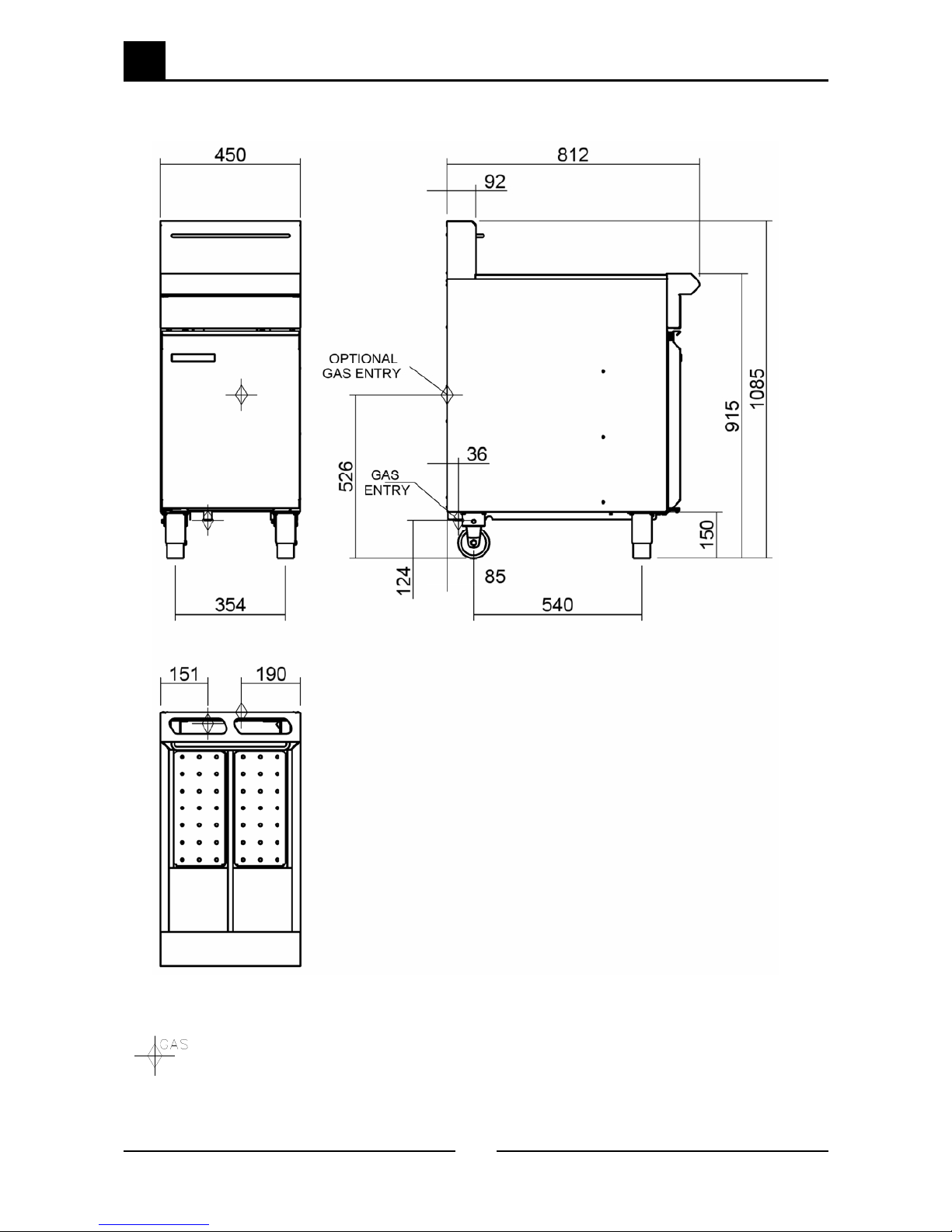
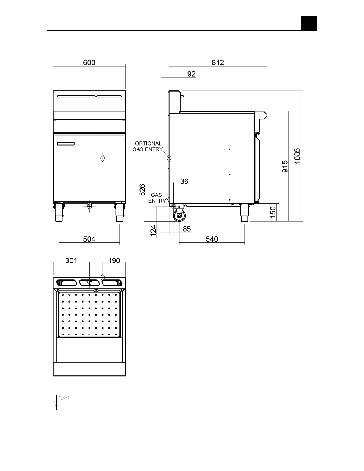
Assembly
This model is delivered completely assembled. Ensure that the legs are securely attached.
NOTE:
• This appliance is fitted with adjustable feet to enable the appliance to be positioned
securely and level. This should be carried out on completion of the gas connection.
Refer to the “Gas Connection” section below.
Optional Accessories (Refer to Replacement Parts List)
• Plinth Kit. For installation details, refer to the instructions supplied with each kit.
Gas Connection
NOTE: ALL GAS FITTING MUST ONLY BE CARRIED OUT BY A QUALIFIED SERVICE PERSON.
1. Blue Seal Fryers do not require an electrical connection, they function totally on the gas supply only.
2. It is essential that the gas supply is correct for the appliance to be installed and that adequate
supply pressure and volume are available. The following checks should therefore be made before
installation:-
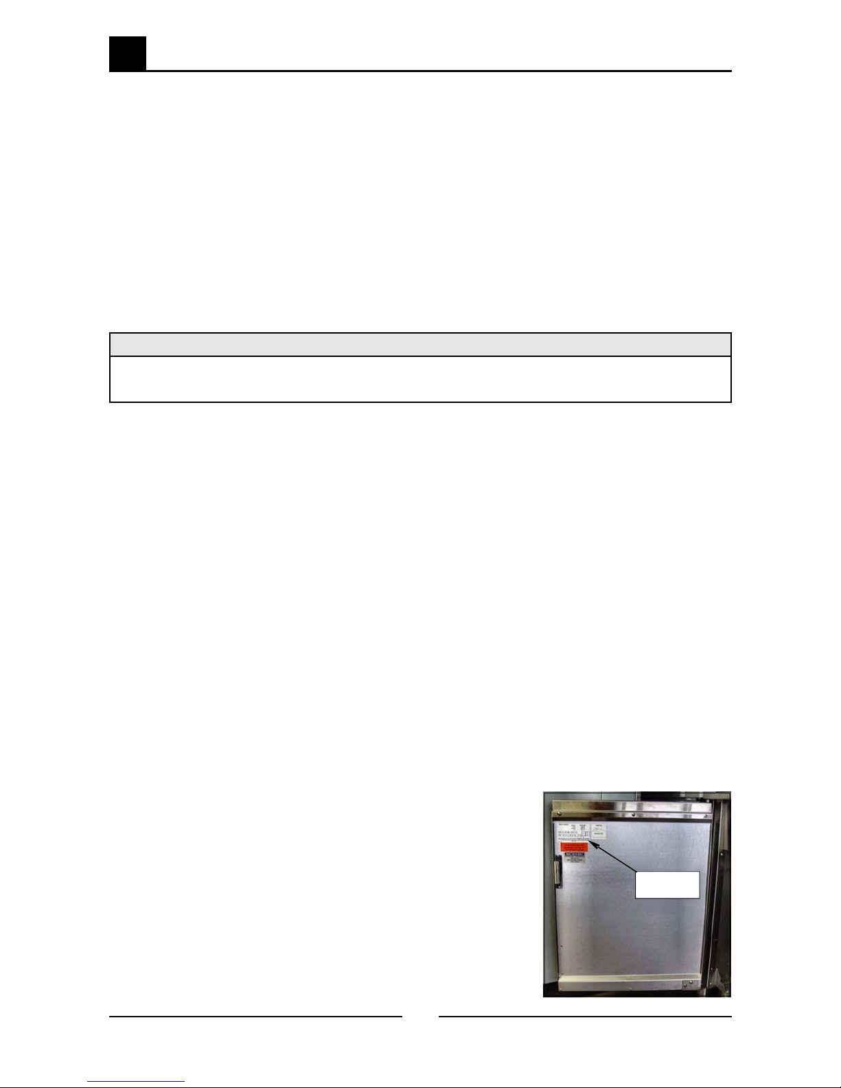
a. The Gas Type the appliance has been supplied for is shown on
coloured stickers located above the gas entry point and next to
the rating plate. Check that this is correct for the gas supply
the appliance is being installed for. The gas conversion
procedure is detailed in this manual.
b. Supply Pressure required for this appliance is shown in the
“Specifications” section of this manual. Check the gas supply to
ensure that adequate supply pressure exists.
c. Input Rate of this appliance is also stated on the Rating Plate
fitted to the inside of the access door and in the
“Specifications” section of this manual. The input rate should
be checked against the available gas supply line capacity.
Particular note should be taken if the appliance is being
added to an existing installation.
Rating Plate
Location
Combustible Surface Non Combustible Surface
Left/Right hand side 50 mm 0 mm
Rear 50 mm 0 mm

Installation
Blue Seal Evolution Series GT45 / GT46 / GT60 © Moffat Ltd, January 200
Revision 1/
NOTE: It is important that adequately sized piping runs directly to the connection joint on the
appliance, with as few tees and elbows as possible to give maximum supply volume.
3. A suitable joining compound which resists the breakdown action of LPG must be used on every gas
line connection, unless compression fittings are used.
The connection to the appliance is 3/4” BSP male.
NOTE: A Manual Isolation Valve must be fitted to the individual appliance supply line.
4. Correctly locate the appliance into its final operating position and using a spirit level, adjust the legs
so that the unit is level and at the correct height.
5. Connect the gas supply to the appliance.
6. Check gas operating pressure to as shown in the “Specifications” section. If the pressure is
incorrect, adjust the pressure by adjusting the regulator screw of the gas control valve as shown in
the ‘Gas Conversion and Specifications’ section.
. Check all gas connections for leakages using soapy water or other gas detecting equipment.
NOTE: The operating pressure is to be measured at the upper test point (Supply Pressure) on the
gas control valve located behind the access door and through the access hole in the control
panel, this is to be carried out with all burners operating at the “High Flame” setting.
8. Turn ‘OFF’ the mains gas supply and bleed the
gas out of the appliance gas lines.
9. Turn ‘ON’ the gas supply and the appliance.
10. Verify the operating pressure remains correct
(Re-adjust if required, using the operating
pressure adjusting screw as shown in the ‘Gas
Conversion and Specifications’ section).
11. Check the pilot flame size. (Re-adjust if
required, using the pilot adjusting screw as
shown in the ‘Gas Conversion and
Specifications’ section).
WARNING:
DO NOT USE A NAKED FLAME TO CHECK FOR GAS LEAKAGES .
Supply Pressure
Test Point
Operating Pressure
Test Point
Pilot Burner
Adjusting Screw
Operating Pressure
Adjusting Screw

Installation
8
Blue Seal Evolution Series GT45 / GT46 / GT60 © Moffat Ltd, January 200
Revision 1/
Commissioning
The following commissioning checks must be carried out before the fryer is handed over for
use, to ensure that the unit operates correctly and the operator(s) understand the correct
operating procedure.
1. Before leaving the new installation;
a. Check the following functions in accordance with the operating instructions specified in the
“Operation” section of the User manual.
• Light the Pilot Burners.
• Light the Main Burners.
• Check the Thermostat Operation (refer to the “Operation” section of the manual).
b. The thermostat operation check should be carried out by filling the fryer with oil/shortening to the
oil 'FILL LEVEL' mark at the rear of the tank (refer to 'Filling the Tank' in the 'Operation Section'
of the Manual) and setting the thermostat to 180°C. Light the pilot burners and turn on the main
burners in accordance with “Operation Instructions” found in the User manual.
c. The calibration of the thermostat should be checked once the oil is up to temperature. If a
discrepancy is found, the thermostat calibration should be referred to the supplier.
d. Ensure that each operator has been instructed in the areas of correct lighting, operation, and
shutdown procedures for the appliance.
2. The User manual must be kept by the owner for future reference and a record of Date of
Purchase
, Date of Installation and Serial Number of Unit recorded and kept with the
manual. (These details can be found on the Rating Plate attached to the inner R/H side
of the front access door panel).
NOTE: If for some reason it is not possible to get the appliance to operate correctly, shut off the
gas supply and contact the supplier of this unit.

3
Operation
9
Blue Seal Evolution Series GT45 / GT46 / GT60 © Moffat Ltd, January 200
Revision 1/
Twin Tank GT46 Controls
3.1 Description of controls
Single Tank GT45 Controls
Flame Failure
Button
Piezo Igniter
Gas Control
Valve
Thermostat
Control Knob
Piezo Igniter
Gas Control
Valve
Flame Failure
Button
Thermostat
Control Knob
Thermostat Control
Knobs for each Tank
Piezo Ignitor
Gas Control
Valve

3 Operation
10
Blue Seal Evolution Series GT45 / GT46 / GT60 © Moffat Ltd, January 200
Revision 1/
Piezo Igniters
Gas Control
Valve
Thermostat
Control Knob
Flame Failure
Button
Single Tank GT60 Controls

3
Operation
11
Blue Seal Evolution Series GT45 / GT46 / GT60 © Moffat Ltd, January 200
Revision 1/
Lighting the Pilot Burners
GT45 Fryer (Single Tank)
1. With the fryer tank full of frying medium, the
pilot burners can be lit.
2. Check that the gas supply is turned on at the
mains supply.
3. Open the access door at the front of the ap-
pliance to access the control panel.
4. Rotate the gas control knob to the position
marked "PILOT" and hold depressed.
5. At the same time hold the flame failure button
depressed.
6. Depress the piezo igniter until the right hand
pilot ignites.
. Continue holding the gas control knob and
flame failure button depressed until the left
hand pilot cross lights from the right hand
pilot.
8. Hold the gas control knob and flame failure
button depressed for approx. 10 to 15
seconds after igniting the second pilot burner,
then release, both pilot burners should remain
alight. If the pilot burners do not ignite,
repeat Items 1 to 8 above.
GT60 Fryer (Single Tank)
1. With the fryer tank full of frying medium, the
pilot burners can be lit.
2. Check that the gas supply is turned on at the
mains supply.
3. Open the access door at the front of the ap-
pliance to access the control panel.
4. Rotate the gas control knob to the position
marked "PILOT" and hold depressed.
5. At the same time hold the flame failure button
depressed.
6. Depress the right hand piezo igniter until the
right hand pilot ignites.
. Continue holding the gas control knob and
flame failure button depressed.
8. Depress the left hand piezo igniter until the
left hand pilot ignites.
9. Hold the gas control knob and flame failure
button depressed for approx. 10 to 15
seconds after igniting both pilot burners, both
pilot burners should remain alight. If the pilot
burners do not ignite, repeat Items 1 to 9
above.
GT46 Fryer (Twin Tank)
1. With the fryer tank full of frying medium, the
pilot burners can be lit.
2. Check that the gas supply is turned on at the
mains supply.
3. Open the access door at the front of the ap-
pliance to access the control panel.
4. Rotate the right hand gas control knob to the
position marked "PILOT" and hold depressed.
5. Depress the right hand piezo igniter until the
right hand pilot ignites.
6. Continue holding the gas control knob de-
pressed for approx. 10 to 15 seconds after
igniting the right hand pilot burner, the pilot
burner should remain alight. If the pilot
burner does not ignite, repeat Items 1 to 6
above.
. To ignite the left hand pilot burner, rotate the
left hand gas control knob to the position
marked "PILOT" and hold depressed.
8. Depress the left hand piezo igniter until the
left hand pilot ignites.
9. Continue holding the gas control knob de-
pressed for approx. 10 to 15 seconds after
igniting the left hand pilot burner, the pilot
burner should remain alight. If the pilot
burner does not ignite, repeat Items to 9
above.
Lighting the Main Burners
1. Ensure that the pilot burners are alight, by
opening the front access door of the appli-
ance and checking that both pilot flames are
alight.
2. Depress and rotate the gas control knob to
the ‘Full Flame’ position.
3. The main burners will now ignite
automatically off the pilot burners.
Note:
• If the main burners are turned on
immediately after the pilot burners are lit, a
delay of approximately 30 seconds will occur
until the thermopile (which provides power
to open the main valve) has heated up off
the pilot burners.
• The main burners will not light if the frying
medium temperature is above the
thermostat set temperature.
• Turning the gas control knob from the pilot
to the main burner position will allow manual
cycling of the burners ‘On’ and ‘Off’ when
melting shortening.

3 Operation
12
Blue Seal Evolution Series GT45 / GT46 / GT60 © Moffat Ltd, January 200
Revision 1/
3. Explanation of Control
System - GT45/GT60
(Single tank fryers)
The gas control circuit in these fryers is operated
by three millivolt circuits.
The first two circuits are the pilot system which
consist of two thermocouples, the pilot burners,
the gas control and a second flame failure valve
separate from the gas control.
The thermocouple from the right pilot is
connected to the main gas control valve, while
the other thermocouple is connected to a
separate flame failure valve downstream from the
gas control pilot gas line. Heat on the
thermocouples from the pilot flames generates a
20-30 mV electrical potential between each
thermocouple and earth. These millivolt circuits
connected to the gas control valve and flame
failure valve are enough to hold the gas valve
magnets within the gas controls open, thereby
allowing the pilot burners to operate.
The third millivolt circuit consists of the
thermopile (a collection of thermocouple
connections in series), and the gas control. Heat
on the thermopile from the pilot flame which is
constantly on as explained above, generates
approximately 500- 00 millivolts which, when
connected to the main burner valve magnet
within the gas control, allows the magnet to pull
open the main burner valve therefore allowing
gas to pass through to the burners.
This main valve circuit is interrupted by the main
thermostat and as the thermostat cycles on/off, it
closes or opens this millivolt circuit, thereby
opening and closing the main burner valve to
cycle the main burners on/off.
The over-temperature thermostat is included in
the pilot millivolt circuit in this same way so that
when it open circuits it cuts the electrical supply
to the main gas valve magnet, thereby shutting
off the pilot burner. The fryer then becomes
inoperable until the oil cools to below 200°C, at
which point the over-temperature thermostat will
close again and allow the millivolt circuit to be
complete, thereby allowing the pilot burner to be
lit again.
The troubleshooting Guide section 5 should be
used to identify any incorrect fryer operation. On
correct identification of the fault, the Trouble-
shooting Guide will make reference to the
corrective action required, or refer to the Fault
Diagnosis section and/or Service section to assist
in correction of the fault.
The gas control circuit in these fryers is operated
by two millivolt circuits.
The first is the pilot system which consists of the
thermocouple, the pilot burner and the gas
control.
Heat on the thermocouple from the pilot flame
generates a 20-30 mV electrical potential
between the thermocouple and earth. This
millivolt circuit connected to the gas control valve
is enough to hold the pilot valve magnet within
the gas control open, thereby allowing the pilot
burner to operate.
The second millivolt circuit consists of the
thermopile (a collection of thermocouple
connections in series), and the gas control. Heat
on the thermopile from the pilot flame which is
constantly on as explained above, generates
approximately 500- 00 millivolts which, when
connected to the main burner valve magnet
within the gas control, allows the magnet to pull
open the main burner valve therefore allowing
gas to pass through to the burners.
This main valve circuit is interrupted by the main
thermostat and as the thermostat cycles on/off, it
closes or opens this millivolt circuit, thereby
opening and closing the main burner valve to
cycle the main burners on/off.
The over-temperature thermostat is included in
the pilot valve millivolt circuit in this same way so
that when it open circuits it cuts the electrical
supply to the pilot valve magnet, thereby shutting
off the pilot burner. The fryer then becomes
inoperable until the oil cools to below 200°C, at
which point the over-temperature thermostat will
close again and allow the millivolt circuit to be
complete, thereby allowing the pilot burner to be
lit again.
The troubleshooting Guide section 5 should be
used to identify any incorrect fryer operation. On
correct identification of the fault, the Trouble-
shooting Guide will make reference to the
corrective action required, or refer to the Fault
Diagnosis section and/or Service section to assist
in correction of the fault.
3.3 Explanation of Control
System - GT46
(Twin tank fryers)

4
Cleaning / Maintenance
13
Blue Seal Evolution Series GT45 / GT46 / GT60 © Moffat Ltd, January 200
Revision 1/
Locking Slide
Locking Slide
CAUTION:
Always turn off the gas supply before
cleaning.
This unit is not water proof.
Do not use water jet spray to clean
interior or exterior of this unit.
General
• To achieve the best results, cleaning must be
thorough, and all controls and mechanical
parts checked and adjusted periodically by a
competent serviceman. If any small faults
occur, have them attended to promptly.
• Don't wait until they cause a complete
breakdown.
Draining and Cleaning
Opening the Drain Valve
a. Lift the locking slide on valve handle to
release valve.
b. While holding the locking slide in the with-
drawn position, rotate the handle anticlock-
wise to open the valve.
c. When the valve is closed, the locking slide
will drop down over the locking valve to
prevent accidental opening of the valve.
Daily Cleaning
a. At the end of each day or at the end of each
shift, if the frying schedule is heavy, the
frying medium should be drained and
strained into a receptacle.
b. Use a drain stick, if necessary, to stir up any
solid medium into the top medium to melt it.
Slip a muslin or other suitable bag over the
drain valve. Crumbs will be caught in the
bag but frying medium will strain freely
through bag into the receptacle. When the
tank is empty, use a small tank with a handle
as a ladle and dip into the hot frying medium
from receptacle and pour vigorously around
sides and bottom of the tank to wash out
crumbs and particles adhering to them.
Continue to dip and pour until all crumbs are
washed down and into the filter bag.
c. Open the drain valve fully and check for any
particles or crumb residue lodged in the
valve. Clean out with a stiff nylon brush. Do
not use wire brush or metal rods as these
damage the seating in the valve and will
eventually lead to valve leakage.
d. If the obstruction in the valve cannot be
removed with a brush, use a wooden probe
to dislodge any obstruction.
e. Once the daily cleaning operation is com-
pleted, close the valve and pour the frying
medium back into the tank and continue the
days work. Straining takes less time than
frying one load of potatoes and will pay
dividends in food quality and saving of frying
medium.

4 Cleaning / Maintenance
14
Blue Seal Evolution Series GT45 / GT46 / GT60 © Moffat Ltd, January 200
Revision 1/
Weekly Cleaning
a. Proceed as for “Daily Cleaning” to drain and
filter the tank. Do not refill the tank with
frying medium until it has been cleaned as
shown below.
b. Fill the fryer with cold water to the normal fill
level and add a high quality commercial
cleaner that has been specifically formulated
for fryers. All purpose cleaners are not
recommended
.
NOTE:
Never use a caustic or lye solution, as this will
leave a fat destroying film on the tank.
c. Heat the water to approximately 80-90°C.
d. Clean the fryer baskets at the same time by
simply immersing them in the cleaning
solution. Allow the fryer to soak for 5-10
minutes or as directed on the cleaner
instructions. Remove the baskets and turn
OFF the main burners.
e. Scrub the baskets and fryer tank lightly, but
vigorously with a stiff nylon bristle brush to
remove any remaining deposits. DO NOT
use a wire brush, as this will scratch
the sides
.
f. Empty the fryer and rinse thoroughly with
water. Use a 1 part vinegar to 15 parts
water solution to rinse the tank and
neutralise any cleaner residue. Use a weaker
solution of up to 1 part to 25 water if this
proves unsuitable for the cleaner being used.
g. Rinse the tank thoroughly with water, drain
and dry. Refill the tank with new filtered
frying medium.

5
Trouble-shooting
15
Blue Seal Evolution Series GT45 / GT46 / GT60 © Moffat Ltd, January 200
Revision 1/
ALL INSTALLATION AND SERVICE REPAIR WORK MUST BE CARRIED OUT BY
QUALIFIED PERSONS ONLY.
WARNING:
Fault Possible Cause Remedy
Piezo ignitor not sparking Short in high tension lead.
(Refer fault diagnosis 5. . )
Piezo faulty.
(Refer fault diagnosis 5. . )
Replace lead.
(Refer service section 6. .14)
Replace piezo.
(Refer service section 6.3.1 )
Pilot won’t light No gas supply
Gas pressure too low.
Knob on gas control won’t go
fully in.
Flame failure valve pilot button
wont go fully in. (GT45 and
GT60)
Blocked pilot spud.
Ensure gas is connected and on
and bottles not empty.
Check gas supply pressure.
(Refer specifications section)
Remove obstruction. Correct
control / wrapper mounting.
Replace gas control.
(Refer service section
6.3.10/6. .11)
Replace flame failure valve.
(Refer to section 6. .15)
Clean or replace pilot spud.
(Refer service section 6. .3)
Pilot goes out when knob released Releasing knob before the
thermocouple heated.
Pilot flame too small.
(Refer fault:Pilot Flame small)
Thermocouple faulty.
(Refer fault diagnosis 5. .1)
Over-temperature thermostat
faulty.
(Refer fault diagnosis 5. .1)
Gas control valve faulty
Flame failure valve faulty
(GT45 and GT60 only)
Hold control in for longer (10 s),
see if pilot will stay lit.
Correct fault.
Replace thermocouple.
(Refer service section 6. .1)
Replace over-temperature
thermostat.
(Refer service section 6. .9)
Replace gas control magnet
Replace flame failure magnet
Pilot flame small Gas pressure too low.
Pilot adjustment screw out of
adjustment.
Pilot injector restricted.
Check gas supply pressure.
(Refer specifications section)
Adjust pilot adjustment screw.
(Refer service section 6.3.1)
Clean pilot injector.
(Refer service section 6. .3)
5.1 Trouble shooting chart

5 Trouble-shooting
16
Blue Seal Evolution Series GT45 / GT46 / GT60 © Moffat Ltd, January 200
Revision 1/
Fault Possible Cause Remedy
Pilot goes out when main burner
comes on
Incorrect gas pressure.
Faulty gas control.
Check supply / adjust pressure.
(Refer specifications section)
Replace gas control.
(Refer service section
6. .10/6. .11)
Pilot goes out while frying, won’t
re-light
Over-temperature thermostat
faulty (oil below 205ºC/401ºF).
(Refer fault diagnosis 5. .1)
Thermostat out of calibration (oil
over 205ºC/401ºF).
Replace over-temperature
thermostat.
(Refer service section 6. .5)
Recalibrate thermostat.
(Refer service section 6.3. )
Pilot goes out while frying, can re-
light
Gas supply - incorrect or
fluctuating pressure.
Draught at installation (blowing
pilot out).
Thermocouple faulty.
(Refer fault diagnosis 5. .1)
Over-temp thermostat faulty.
(Refer fault diagnosis 5. .1)
Main gas control valve faulty.
Flame failure valve faulty
(GT45 and GT60 only)
Check supply / adjust pressure.
Shield fryer from excessive breeze
Replace thermocouple.
(Refer service section
6. .1/6. . )
Replace.
(Refer service section 6. .5)
Replace gas contro0l magnet.
Replace flame failure magnet.
Main burners will not light Incorrect supply pressure.
Wrong size or blocked injectors.
Small pilot flame.
(Refer fault:Small Pilot Flame)
Faulty thermopile.
(Refer fault diagnosis 5. .3)
Faulty thermostat.
(Refer fault diagnosis 5. .3)
Faulty gas control.
(Refer fault diagnosis 5. .3)
Check supply correct pressure.
Replace / clean injectors.
(Refer service section 6. .7)
Correct fault.
Replace thermopile.
(Refer service section
6. .1/6. . )
Replace thermostat
(Refer service section 6. .5)
Replace gas control.
(Refer service section
6. .10 /6. .11)
Other manuals for Evolution GT45
1
This manual suits for next models
2
Table of contents
Other Blue Seal Fryer manuals

Blue Seal
Blue Seal Evolution Series User manual

Blue Seal
Blue Seal GT45E User manual

Blue Seal
Blue Seal Fast-Fri E43 User manual

Blue Seal
Blue Seal Evolution GT45 User manual

Blue Seal
Blue Seal Evolution Series User manual

Blue Seal
Blue Seal Fast-Fri E43 User manual

Blue Seal
Blue Seal Evolution GT18 Series User manual

Blue Seal
Blue Seal GT45E User manual

Blue Seal
Blue Seal E603 User manual

Blue Seal
Blue Seal E603 User manual