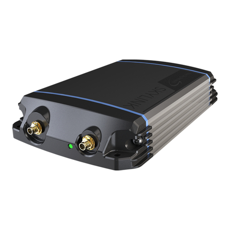
Blue Sky Network D2000 User manual

D2000 (P/N 100340)
IRIDIUM SATELLITE PACKET DATA TERMINAL
Installation Guide
Document Part # 100341
Revision A

Blue Sky Network May 2009
Page ii D2000 IRIDIUM SATELLITE PACKET DATA TERMINAL Doc# 100341
COPYRIGHT
Copyright 2006-2009 Blue Sky Network
All rights reserved. No part of this manual may be reproduced, stored or distributed without written
permission of Blue Sky Network.
Blue Sky Network reserves the right to change or update specifications without notice.
Publication Date: May 2009
Information in this manual is current as of publication or revision date. Specifications and operational
details are subject to change without notice, at the discretion of Blue Sky Network, LLC.
This manual is available in PDF format at www.blueskynetwork.com, or by request at
support@blueskynetwork.com or sales@blueskynetwork.com.
www.blueskynetwork.com
Phone: +1-858-551-3894
Fax: +1-858-551-3891
1298 Prospect Street, Suite 1D
La Jolla, CA 92037

May 2009 Blue Sky Network
100322 D2000 IRIDIUM SATELLITE PACKET DATA TERMINAL Page iii
REVISION HISTORY
Revision Number
Date
Author
Document
Number
Notes
A
May 2009
Randy Warner / Kelly
Musgrove
100341
Configuration
Update

Blue Sky Network May 2009
Page iv D2000 IRIDIUM SATELLITE PACKET DATA TERMINAL Doc# 100341
TABLE OF CONTENTS
INTRODUCTION .............................................................................................................1
APPLICATION ..................................................................................................................1
OVERVIEW ......................................................................................................................1
SYSTEM DESCRIPTION & OPERATION .......................................................................2
D2000 NETWORK DESCRIPTION.......................................................................................2
IRIDIUM SATELLITE NETWORK...........................................................................................3
GPS SATELLITE NAVIGATION SYSTEM ..............................................................................3
D2000 OVERVIEW..........................................................................................................4
SPECIFICATIONS..............................................................................................................4
FEATURES ......................................................................................................................4
ANTENNA CONFIGURATIONS:............................................................................................4
FRONT PANEL .................................................................................................................5
BACK PANEL ...................................................................................................................5
INSTALLATION .................................................................................................................5
ANTENNAS ......................................................................................................................8
AVIATION ANTENNA (AT1621-62W-SMAF-SMAF-000-03-26-NM):..................................8
AVIATION ANTENNA SPECIFICATIONS ................................................................................9
MARINE ANTENNA (AT1621-162W-SMAF-SMAF-000-03-26-NM):................................10
MARINE ANTENNA SPECIFICATIONS ................................................................................11
LAND ANTENNA (AT1621-262W-SMAF-SMAF-000-03-26-NM): ...................................12
LAND ANTENNA SPECIFICATIONS ....................................................................................13
ANTENNA & ANTENNA CABLE INSTALLATION ....................................................................14
ANTENNA CABLE ROUTING CONSIDERATIONS ..................................................................14
D2000 WIRING DIAGRAM ..............................................................................................15
POWER INPUT AND ACCESSORIES...................................................................................16
POWER CONNECTIONS ..................................................................................................16
POWER OPTIONS ........................................................................................................17
POWER-UP TEST .........................................................................................................19
SERVICE ACTIVATION.................................................................................................20
PRODUCT WARRANTY................................................................................................21

May 2009 Blue Sky Network
Doc# 100341 D2000 IRIDIUM SATELLITE PACKET DATA TERMINAL Page 1
INTRODUCTION
Application
This guide is applicable to the following components:
Part Number
Component Description
100340AD
D2000AD Packet Data Terminal (aviation firmware)
100340MD
D2000MD Packet Data Terminal (land/mobile firmware)
100297
D2000 Power Cigarette Lighter Adapter
100298
D2000 Power Supply Adapter (110/220V sources)
AT1621-62W-TNCF-
SMAF-000-03-26-NM
Iridium/GPS Combined Antenna (aviation)
AT1621-62W-SMAF-
SMAF-000-03-26-NM
Iridium/GPS Combined Antenna (land/mobile)
AT1621-162W-SMAF-
SMAF-000-03-26-NM
Iridium/GPS Combined Antenna (marine)
Notes
Overview
The information contained in this manual describes the features, functions, technical
characteristics, components, installation considerations and setup procedures for
Blue Sky Network’s D2000 IRIDIUM SATELLITE PACKET DATA TERMINAL.
Information, drawings and wiring diagrams contained in this manual are
intended as a reference for engineering planning only. Drawings and wiring
diagrams contained herein do not represent any specific vehicle or vessel
installation. It is the installer’s responsibility to create installation drawings
specific to the asset.

Blue Sky Network May 2009
Page 2D2000 IRIDIUM SATELLITE PACKET DATA TERMINAL Doc# 100341
SYSTEM DESCRIPTION & OPERATION
D2000 Network Description
The Blue Sky Network’s D2000 is an Iridium Satellite Packet Data Terminal. Roughly
the size of a car stereo, it can easily be installed on a marine vessel, land vehicle, or
aircraft for instant global tracking and 2-way data communications.
All data services are managed by the customer through our web-based SkyRouter
portal. SkyRouter offers global asset tracking, account management features, such
as user authorization, asset settings, messaging and billing information. Access to
SkyRouter is highly secure and password protected.

May 2009 Blue Sky Network
Doc# 100341 D2000 IRIDIUM SATELLITE PACKET DATA TERMINAL Page 3
Iridium Satellite Network
The Iridium Satellite System is the only current provider of truly global, mobile
satellite voice and data solutions with complete coverage of the Earth including
oceans, airways and Polar regions. Through a constellation of 66 low-earth orbiting
(LEO) satellites operated by Boeing, Iridium delivers essential communications
services to and from remote areas where terrestrial communications are not
available. The service is perfectly suited for the transportation industry as well as
industrial applications such as heavy construction, defense/military, emergency
services, maritime, mining, forestry, oil and gas.
Satellites ............................... 66 (plus 6 in-orbit backup satellites)
Orbital Planes ....................... 6
Orbit Altitude ......................... 485 miles (780 kilometers)
Inclination of Orbital Plane .... 86.4 degrees
Orbital Period........................ 100 minutes, 28 seconds
Satellite Weight..................... 1,500 pounds (689 kilograms)
Spot Beams .......................... 48 per satellite (30 miles in diameter per beam)
GPS Satellite Navigation System
The Global Positioning System (GPS) is a worldwide radio-navigation system
formed from a constellation of satellites and their ground stations.
GPS uses these "man-made stars" as reference points to calculate positions
accurate to a matter of meters.
GPS satellite signals are processed in a GPS receiver, enabling the receiver to
compute position, velocity and time. GPS receivers have been miniaturized to just a
few integrated circuits, and are becoming very economical, which makes the
technology accessible to virtually everyone.
While there are thousands of civil users of the GPS system world-wide, the system
was designed for the U. S. military. GPS is funded and operated by the U. S.
Department of Defense (DOD).

Blue Sky Network May 2009
Page 4D2000 IRIDIUM SATELLITE PACKET DATA TERMINAL Doc# 100341
D2000 OVERVIEW
Specifications
Height 3.0 inches (7.62 cm)
Width 6.5 inches (16.51 cm)
Depth 7.5 inches (19.05 cm)
Weight 2.2 pounds (1Kg)
Power Requirements 10VDC - 33VDC
Nominal Current 0.5A Continuous, 1.5A Peak (12V, battery charging)
Operating Temperature Range -20 degrees C to + 60 degrees C
Altitude Up to 50,000 feet
Iridium SBD Frequency L-Band
GPS Frequency L-Band
Laptop/PDA I/O Ethernet Port
Sensor Data I/O 1 Serial Port (RS-232)
Antenna Connectors:
Aviation: TNC jack for Iridium, SMA jack for GPS
Land: SMA jack for Iridium, SMA jack for GPS
Marine: SMA jack for Iridium, SMA jack for GPS
Vibration and Humidity Tests SAE 1455
Features
Worldwide - The D2000 is a truly global satellite communication solution. Using the
Iridium Satellite Network, Blue Sky has exploited an efficient and cost effective
communication delivery system.
GPS - The D2000 has an integrated 12 channel GPS receiver. Users can define
position reporting intervals and other operating parameters either locally, or remotely
through the SkyRouter portal.
Asset Tracking - Directly from our web-portal, SkyRouter (www.blueskynetwork.com),
users can view the location of one or a fleet of mobile assets. Tracking data can also
be utilized by third party tracking solutions.
Portability - The D2000 may be used as a portable unit.
Antenna Configurations:
The D2000 100340AD version (for aviation) utilizes a TNC jack for the Iridium
antenna and an SMA jack for an amplified GPS antenna for enhanced signal levels
in challenging RF environments.
The D2000 100340MD version (for land/marine) utilizes a SMA jack for the Iridium
antenna and an SMA jack for an amplified GPS antenna for enhanced signal levels
in challenging RF environments.

May 2009 Blue Sky Network
Doc# 100341 D2000 IRIDIUM SATELLITE PACKET DATA TERMINAL Page 5
Front Panel
A. 4-Way Menu Navigation
Button
B. LCD Display Screen
C. Quick Position / Mayday
Alert Button
D. OK (Enter) Button
E. Numerical Pad
F. Clear Button
Back Panel
100340- Combined Antenna Configuration
A. Antenna Connector (TNC)
B. Antenna Connector (SMA)
C. Circular Power Connector
D. Power Switch
E. Serial Port
F. Maintenance Port (for
firmware upgrade)
G. Ethernet Port
Installation
The location of the D2000 is at the discretion of the user, but consideration should be given
to space, environmental conditions and distance from the antenna. The Optional U-Shaped
Mounting Bracket (p/n 100307-3, below) can be provided with the unit and should assist the
installer with placing the unit in a dashboard, ceiling or other available space (please call
Blue Sky Network for ordering information). The D2000 has a pair of notches in each side
(top and bottom) of the unit, allowing a solid link of the Mounting Bracket on the D2000.

Blue Sky Network May 2009
Page 6D2000 IRIDIUM SATELLITE PACKET DATA TERMINAL Doc# 100341
The Mounting Bracket can be assembled directly into any surface with the appropriate
mounting holes, or can be used with the optional suction mount, as shown below. Using the
suction mount option with the D2000 allows for higher mechanical flexibility and better
visualization of the front panel.

May 2009 Blue Sky Network
Doc# 100341 D2000 IRIDIUM SATELLITE PACKET DATA TERMINAL Page 7
1. D2000 Unit
2. Mounting Bracket (p/n 100307-3).
3. Screws (10-32 x .5LG SS Pan
Head)
4. Suction Mount (three variations).
Item sold separately by Blue Sky
Network, please call for details.
5. Lock washers
6. Hex Nuts (10-32)
Top View (bracket holding into two notches)
“Goose Neck” Suction Mount

Blue Sky Network May 2009
Page 8D2000 IRIDIUM SATELLITE PACKET DATA TERMINAL Doc# 100341
Antennas
The D2000 antenna configuration uses a combined Iridium/GPS antenna. The Iridium RF and the
GPS RF signals are routed through separate coaxes. Several suitable antennas for this
configuration are illustrated below.
Aviation Antenna (AT1621-62W-SMAF-SMAF-000-03-26-NM):

May 2009 Blue Sky Network
Doc# 100341 D2000 IRIDIUM SATELLITE PACKET DATA TERMINAL Page 9
Aviation Antenna Specifications
Frequency: 1621 ±5 MHz
1575 ±5 MHz
Polarization: Right Hand Circular
Axial Ratio: 3 dB Max
Iridium Radiation Coverage
Elevation Angle: 0°<Ө<10° Gain: -2.5 dBic min
10°<Ө<90° Gain: 0 dBic min
GPS Radiation Coverage
Elevation Angle: 0°<Ө<10° Gain: -7.5 dBic min
10°<Ө<20° Gain: -5.5 dBic min
20°<Ө<30° Gain: -3.5 dBic min
Ө>30° Gain: -2.5 dBic min
Amplifier
Gain: Iridium: Passive
GPS L1: 26 dB (35mA)
Voltage: Iridium: Passive
GPS L1: 3 VDC
Noise Figure: 2.5 dB Max
Impedance: 50 Ohms
VSWR: ≤2.0:1
Power Handling: 10 Watts
Connectors: SMA / TNC
Weight: 4.50 oz
Altitude: 55,000’
Operating Temp: -55°C to +85°C
Designed to: DO-160E
ENV CAT: F2-ABB[S(CLMY)U(FF1)]XSFDFSZXXXXPX[A3][2A]CX
TSO: C-144

Blue Sky Network May 2009
Page 10 D2000 IRIDIUM SATELLITE PACKET DATA TERMINAL Doc# 100341
Marine Antenna (AT1621-162W-SMAF-SMAF-000-03-26-NM):
The marine antenna utilizes a robust molded radome that provides protection against severe
weather normally encountered in marine environments. Included with the antenna is marine
mount adapter, allowing for simple installation on standard marine antenna poles.

May 2009 Blue Sky Network
Doc# 100341 D2000 IRIDIUM SATELLITE PACKET DATA TERMINAL Page 11
Marine Antenna Specifications
Iridium element: 1621 MHz +/- 5MHz
VSWR: <2:1
Polarization: Right Hand Circular Polarization (RHCP)
Element type: Passive patch
Impedance: 50 ohms
Power Handling: 10 watts
Element gain: 0 dBic min @ Zenith
RF connector: SMA jack
GPS element: 1575 MHz +/- 5MHz
VSWR: <2:1
Polarization: Right Hand Circular Polarization (RHCP)
Element type: Passive patch
Impedance: 50 ohms
Power Handling: 10 watts
Element gain: -2.5 dBic min @ Zenith
Amplifier gain: +26 dB
Amplifier power requirements: +3VDC at 35mA typical
RF connector: SMA jack

Blue Sky Network May 2009
Page 12 D2000 IRIDIUM SATELLITE PACKET DATA TERMINAL Doc# 100341
Land Antenna (AT1621-262W-SMAF-SMAF-000-03-26-NM):

May 2009 Blue Sky Network
Doc# 100341 D2000 IRIDIUM SATELLITE PACKET DATA TERMINAL Page 13
Land Antenna Specifications
Frequency: 1621 ±5 MHz
1575 ±5 MHz
Polarization: Right Hand Circular
Axial Ratio: 3 dB Max
Iridium Radiation Coverage
Elevation Angle: 0°<Ө<10° Gain: -2.5 dBic min
10°<Ө<90° Gain: 0 dBic min
GPS Radiation Coverage
Elevation Angle: 0°<Ө<10° Gain: -7.5 dBic min
10°<Ө<20° Gain: -5.5 dBic min
20°<Ө<30° Gain: -3.5 dBic min
Ø>30° Gain: -2.5 dBic min
Amplifier
Gain: Iridium: Passive
GPS L1: 26 dB (35mA)
Voltage: Iridium: Passive
GPS L1: 3 VDC
Noise Figure: 2.5 dB Max
Impedance: 50 Ohms
VSWR: ≤2.0:1
Power Handling: 10 Watts
Connectors: SMA / TNC
Weight: 4.50 oz
Operating Temp: -55°C to +85°C

Blue Sky Network May 2009
Page 14 D2000 IRIDIUM SATELLITE PACKET DATA TERMINAL Doc# 100341
Antenna & Antenna Cable Installation
For optimum performance, the antenna must be installed on the upper surface of the
vehicle body, with an unrestricted view of the sky down to eight degrees above the
horizon.
Transmission from the antenna may be affected by, and can affect the operation of
other systems and it is the installer’s responsibility to evaluate the location for any
possible RF interference. In particular, the Iridium frequency is near the allocated
GPS and Inmarsat band. The antenna should be at least 35 inches (or 1 meter) from
any L-band antennas, particularly another GPS antenna.
Strict maximum attenuation requirements for the coax cable and connectors
that link the Antenna to the D2000 Unit must be observed. The Iridium signal
loss budget, including the antenna cable and all connectors from the antenna to the
D2000 Unit is < 1.5dB @1621MHz. The BSN Installation Kits include low loss coax
antenna cables sized to meet this requirement.
Antenna Cable Routing Considerations
The length and routing of cables must be carefully planned before starting the
installation.
Avoid sharp bends in the cable. Exceeding the maximum bend radius of the
antenna coax cable may result in permanent degradation of the cable signal.
In order to ensure optimum performance, the D2000 and associated wiring
should be kept away from high noise sources and not routed with cables from
high power sources.
Other options for installing the antenna are available. One method is to have it in a portable
mode inside the vehicle. The diagram below shows an example of how Antenna Suction
Mounting hardware (sold by Blue Sky Network) can be used to place the antenna from the
inside of the vehicle’s windshield.
Land antenna setup w/
suction mount

May 2009 Blue Sky Network
Doc# 100341 D2000 IRIDIUM SATELLITE PACKET DATA TERMINAL Page 15
D2000 Wiring Diagram
The D2000 requires power and antenna to operate, but there are additional wiring
options to enhance the D2000 usability. For instance, the user might opt to install a
visual or audio alert device in order to signal the operator that a message has arrived
from the dispatch center.
Please note: The DB9F port has limited capability. 3rd party devices such as sensors
need additional software to function. BSN is not responsible for developing software for
such devices.

Blue Sky Network May 2009
Page 16 D2000 IRIDIUM SATELLITE PACKET DATA TERMINAL Doc# 100341
Power Input and Accessories
The D2000 power interface supports wide voltage input in the range of 10V to 33V
DC. The following power is the most commonly used:
•24 VDC nominal, typically less than 0.2A while operating, 0.4A when
transmitting.
•12 VDC nominal, typically less than 0.4A while operating, 0.8A when
transmitting.
Power Connections
The D2000 (P/N100340xx) uses a weatherproof 8-Pin EN3 Switchcraft connector for
power input. A mating pigtail (shown below) is included with the D2000 to facilitate
installation of the newer D2000 in areas formerly occupied by the old D2000
(100300xx) configuration, and to easily connect to the Cigarette Lighter Adapter Wall
Power Adapter, or External Battery (shown below).
If the user does not wish to build a fixed power harness to the D2000, power may
also be provided by a Cigarette Lighter Adapter (p/n 100297), Wall Power Adapter
(p/n 100298) or External Battery (RB-HC10R2T-MT5000)- all sold by Blue Sky
Network.
D2000 Cigarette Lighter Adapter
(100297)
D2000 Wall Power Adapter
(100298)
D2000 External Battery
(RB-HC10R2T-MT5000)
This manual suits for next models
1
Table of contents
Other Blue Sky Network Touch Terminal manuals
