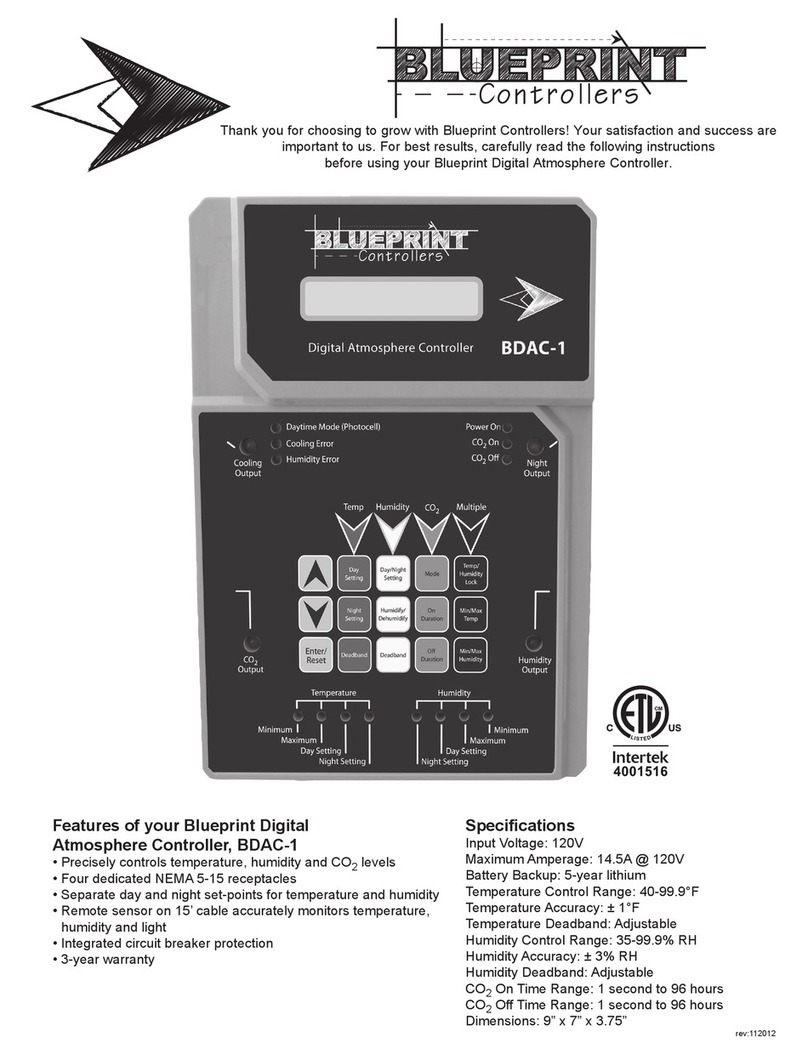
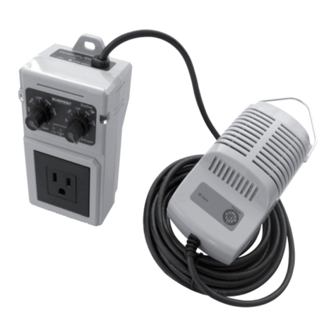
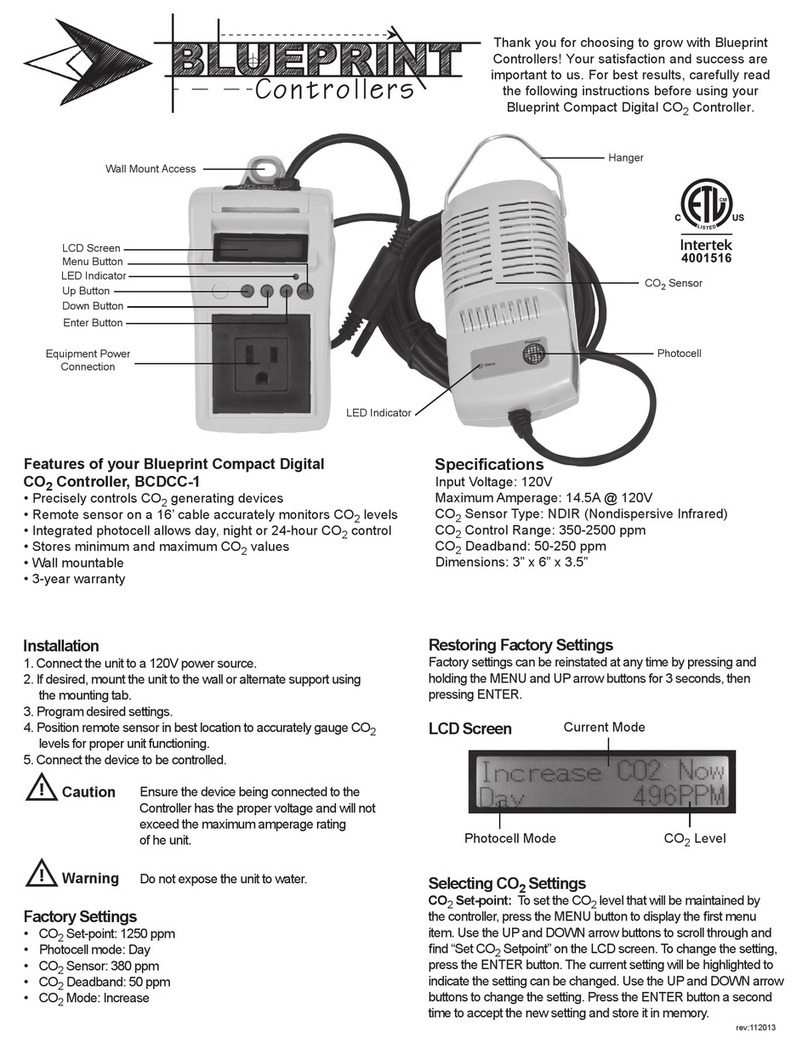
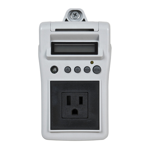
Blueprint Controllers BDAC-2 User manual

rev:112012
Thank you for choosing to grow with Blueprint Controllers! Your satisfaction and success
are important to us. For best results, carefully read the following instructions
before using your Blueprint Digital Atmosphere Controller with Fuzzy Logic.
Features of your Blueprint Digital
Atmosphere Controller with Fuzzy Logic
• Precisely controls temperature, humidity and CO2levels
• Fuzzy Logic mode allows more precise control of CO2
levels when using compressed CO2
• Four dedicated NEMA 5-15 receptacles
• Separate day and night set-points for temperature and humidity
• Remote sensor on 15’ cable accurately monitors temperature,
humidity and light
• Integrated circuit breaker protection
• 3-year warranty
Specications
Input Voltage: 120V
Maximum Amperage: 14.5A @ 120V
Temperature Control Range: 40-99.9°F
Temperature Accuracy: ± 1°F
Temperature Deadband: Adjustable
Humidity Control Range: 35-99.9% RH
Humidity Accuracy: ± 3% RH
Humidity Deadband: Adjustable
CO2 Control Range: 350-2000 ppm
CO2 Accuracy: ± 75 ppm
Dimensions: 9” x 7” x 3.75”

Installation
• Mount the Controller on the wall. Place the remote sensor at plant
height in an area with good air circulation. Avoid placing the sensor in
a location with direct, intense exposure to light.
• Connect the sensor cable to the bottom of the unit using the
quick-disconnect screw.
• Plug the Controller into a 120V NEMA 5-15 wall outlet.
• Turn the power on and allow the unit to warm up for 5 minutes.
While the unit is warming up, the display will read “CO2 heat.”
• Program the desired settings before connecting any devices.
• Plug the devices to be controlled by the unit into the
receptacles on the unit’s sides.
• Ensure the devices being connected to the
Controller have the proper voltage and will
not exceed the maximum amperage rating
of the unit.
• Before using a sulfur vaporizer around the
Controller, remove the remote sensor
from the affected area or turn the unit off
and cover the sensor with a protective
plastic bag. Remove the bag before turning
the Controller back on. Note: Failure to
protect the remote sensor during sulfur use
will result in damage to the infrared CO2
sensor and void the warranty.
• Do not expose the unit to water.
Factory Settings
The Controller is preprogrammed with the following
factory settings:
• Temperature Day Setting: Cooling – 80°F / heating – 55°F
• Temperature Night Setting: Cooling – 70°F / heating – 55°F
• Temperature Deadband: 3°F cooling and heating
• Humidity Setting: 50% RH
• Humidity Mode: Decrease
• Humidity Deadband: 5%
• CO2 Level: 1250 ppm
• CO2 Deadband: 50 ppm
• CO2 Calibration: 380 ppm
• Temperature/Humidity Lock: Split
• Temperature/CO2 Lock: Split
Restoring Factory Settings: Hold the “Enter/Reset” and DOWN
arrow buttons for 3 seconds. The display will read “f.Set.” Press the
“Enter/Reset” button again to restore the default factory settings. When
the process is complete, the display will read “donE.” Note: It may take
up to 15 seconds to complete the process.
Error LEDs
When the Controller is functioning normally, the ambient CO2level,
temperature and humidity will change slowly but steadily. If the
Controller does not detect a change in CO2level, temperature or
humidity within a 1-hour period, the unit will deactivate the affected
output and the corresponding green error LED will ash to indicate
which device may be malfunctioning. Ensure the device and remote
sensor are functioning properly. To reset the error, press the
“Enter/Reset” button.
Adjusting Photocell Sensitivity
• To change the photocell’s sensitivity, hold the DOWN arrow
button for 3 seconds. The current setting will be displayed.
• Press the UP arrow button to increase the number displayed,
decreasing the amount of light required to activate the photocell.
• Press the DOWN arrow button to decrease the number displayed,
increasing the amount of light required to activate the photocell.
• Press “Enter/Reset” to accept the new setting.
Selecting Temperature Settings
Temperature Display: Hold the UP and DOWN arrow
buttons for 3 seconds to change the temperature display from
Fahrenheit to Celsius.
Temperature Day: The Controller allows day cooling and day
heating set-points. To set the temperature at which the cooling
output will be activated during the day, press the “Day Setting”
button. The display will read “CooL__F.” Use the UP and DOWN
arrow buttons to adjust the setting. Press “Enter/Reset” to accept
the new setting. To set the temperature at which the heating output
will be activated during the day, press the “Day Setting” button twice.
The display will read “HEAt__F.” Use the UP and DOWN arrow
buttons to adjust the setting. Press “Enter/Reset” to accept the
new setting.
Temperature Night: The Controller allows night cooling and
night heating set-points. To set the temperature at which the cooling
output will be activated at night, press the “Night Setting” button. The
display will read “d.CooL__F.” Use the UP and DOWN arrow buttons
to adjust the setting. Press “Enter/Reset” to accept the new setting.
To set the temperature at which the heating output will be activated
at night, press the “Night Setting” button twice. The display will read
“HEAt__F.” Use the UP and DOWN arrow buttons to adjust the set-
ting. Press “Enter/Reset” to accept the new setting.
Temperature Deadband: The Controller allows cooling and
heating deadband settings. To set the cooling deadband, press the
“Deadband” button under “Temp.” The display will read “d.CooL__F.”
Use the UP and DOWN arrow buttons to adjust the setting. Press
“Enter/Reset” to accept the new setting. To set the heating dead-
band, press the “Deadband” button twice under “Temp.” The display
will read “d.HEAt__F.” Use the UP and DOWN arrow buttons to
adjust the setting. Press “Enter/Reset” to accept the new setting.
Note: To prevent the unit from activating both the cooling and
heating devices at the same time, the difference between the heating
and cooling set-points must be greater than the combined deadband
set-points.
Selecting Humidity Settings
Humidity Day: To select the humidity level at which the humidity
output will be activated during the day, press the “Day/Night Setting”
button. The display will read “dAy_rH.” Use the UP and DOWN arrow
buttons to adjust the setting. Press “Enter/Reset” to accept the
new setting.
Humidity Night: To select the humidity level at which the humidity
output will be activated at night, press the “Day/Night Setting” button
twice. The display will read “nit_rH.” Use the UP and DOWN arrow
buttons to adjust the setting. Press “Enter/Reset” to accept the
new setting.
Humidity Mode: To select between humidifying and
dehumidifying modes, press the “Humidify/Dehumidify” button.
The display will show the current setting, “rh_Incr” for humidifying
and “rh_dEcr” for dehumidifying. Use the UP and DOWN arrow but-
tons to choose between modes. Press “Enter/Reset” to accept the
new setting.
Humidity Deadband: To set the humidity deadband, press the
“Deadband” button under “Humidity.” The display will show the
current setting. Use the UP and DOWN arrow buttons to
adjust the setting. Press “Enter/Reset” to accept the new setting.
Caution
Warning

Selecting CO2Settings
CO2ppm Setting: To select the CO2 ppm set-point, press the “ppm
Setting” button. The current setting will be displayed. Use the UP and
DOWN arrow buttons to adjust the setting. Press “Enter/Reset” to accept
the new setting.
CO2Deadband: To select the CO2 deadband set-point, press the
“Deadband” button under “CO2.” Use the UP and DOWN arrow buttons
to adjust the setting. Press “Enter/Reset” to accept the new setting.
Locking Temperature/Humidity Functions
The temperature and humidity functions may be set to operate locked
(“connECt”) or split (“SPLit”). Press “Temp/Humidity Lock” to display the
current setting. Use the UP and DOWN arrow buttons to select a new
setting. Press “Enter/Reset” to accept the new setting.
• Select “connECt” if using only ventilating fans for cooling and
removing humidity. The fan will turn on when the sensor detects an
increase above the set-point in either humidity or temperature.
• Select “SPLit” if using a ventilating fan or AC unit for cooling and a
dehumidier for removing humidity. The cooling device will turn
on when the temperature rises above the set-point, and the
dehumidier will turn on when the humidity rises above the set-point.
• Select “SPLit” if using a fan or AC unit for cooling and a humidier for
adding humidity. The cooling device will turn on when the temperature
rises above the set-point and the humidier will turn on when the
humidity drops below the set-point.
Locking Temperature/CO2Functions
The temperature and CO2functions may be set to operate locked
(“connECt”) or split (“SPLit”). Press “Temp/CO2 Lock” to display the
current setting. Use the UP and DOWN arrow buttons to select a new
setting. Hold “Enter/Reset” for 3 seconds to accept the new setting.
• Select “connECt” if using ventilating fans for cooling and a
compressed CO2 setup. The CO2will be deactivated when the fans
are activated, allowing the fans to exchange air while minimizing loss
of CO2.
• Select “SPLit” if using a recycling air conditioner for cooling and a
compressed CO2 setup. The air conditioner and compressed CO2will
be activated independently.
• Select “SPLit” if using ventilating fans for cooling and a CO2
generator. The ventilation fans and CO2generator will be
activated independently.
• Select “connECt” if using a recycling air conditioner and a CO2
generator. The CO2generator will be deactivated while the air
conditioner is operating to reduce the amount of heat the air
conditioner must offset.
Displaying Recorded Values
Press the “Min/Max Recall” button to display the minimum and maximum
recorded values for temperature, humidity and CO2 level. Press the
button repeatedly to cycle through the values in the following order: max.
temperature, min. temperature, min. humidity, max. humidity, min. CO2,
max. CO2. Press “Enter/Reset” to reset a displayed value.
Fuzzy Logic Mode
Fuzzy Logic mode counters rising or falling CO2levels by quickly
activating the CO2 solenoid valve, allowing CO2levels to be controlled
more precisely. This function can be used only with compressed CO2.
Do not use Fuzzy Logic with a CO2generator.
Hold “Enter/Reset” for 5 seconds to activate or deactivate Fuzzy Logic
mode. Use the UP and DOWN arrow buttons to choose between Fuzzy
Logic mode (“LogIcon”) if using compressed CO2and generator mode
(“gEnErAt”) if using a CO2 generator. Press “Enter/Reset” to accept the
new setting.
Calibrating the CO2Sensor
• Place the Controller and sensor outdoors in a shaded area.
Note: If the unit is calibrated in a high-trafc or highly populated
area, a slightly higher calibration value of 400-475 ppm
is recommended.
• Plug in the Controller and allow it to warm up for a minimum of
30 minutes but 1 hour is recommended.
• Press the “Calibrate CO2 Sensor” button to activate automatic
calibration. Do not breathe on the unit while the calibration
function is activated.
• Press “Enter/Reset” to start the calibration sequence. “Co2_
CAL” will be displayed and the CO2 calibration LED will blink.
• When it is complete, the screen will display normal functions.
Calibration will not affect any other settings. Note: It may take up
to 10 minutes to complete the calibration process.
FAQ
•HowcanItelliftheCO2readingisaccurate?
Check the calibration of the CO2sensor by placing the
sensor outdoors for 30 minutes. The reading should be
about 380 ppm. If not, see the “Calibrating the CO2
Sensor” section.
•Whatifthetemperaturereadingishigh?
Verify the remote sensor is not in a location with direct,
intense exposure to light.
•Dothehumidityandtemperaturesensorsneedto
becalibrated?
No. The humidity and temperature sensors are digital and
do not require calibration.
Troubleshooting
•Whydoesthedisplayread“ErrSEn”?
The remote sensor is not connected or not
communicating with the controller. Verify the cable is
connected and the remote sensor is powered.
•WhyarethesmallerrorLEDsilluminated?
The sensor or a connected device is malfunctioning. See
the “Error LEDs” section for more information.
•Whyisn’ttheCO2outputbeingactivated?
Verify the correct CO2mode has been selected and verify
the “Daytime mode (photocell)” is illuminated.
•Whyisn’ttheControllerpoweringthe
connecteddevices?
Reset the circuit breaker. Ensure the device to be controlled
is working correctly by plugging the device into a reliable
power source. Verify the Controller is being supplied the
correct voltage.
Optional PC Connection
Downloadable software and a USB connection cable (available
separately) may be used to change the Controller’s settings, verify
outputs are operating, and record and chart conditions in the growing
area using a personal computer. Download the necessary software
and instructions at www.Sunleaves.com.
This device complies with part 15 of the FCC Rules. Operation is subject to the following two conditions:
(1) This device may not cause harmful interference, and (2) this device must accept any interference
received, including interference that may cause undesired operation.

7854 North State Road 37
Bloomington, IN 47404
Phone: 888-464-9676
Email: [email protected]
Sunleaves Garden Products
Limited 3-Year Warranty Terms
Sunleaves Garden Products warrants that the Blueprint Digital Atmosphere Controller with Fuzzy Logic will
remain free from appearance of defects in workmanship and materials for 3 years from date of original retail
purchase. This warranty is subject to the following limitations: (a) manufacturer’s liability is limited to the
replacement or repair of the unit, as decided by the manufacturer; (b) a defective unit must be returned, pre-
paid, with proof of purchase to the point of purchase or as instructed below; and (c) this warranty does not
apply to defects resulting from the alteration, abuse, accidental damage, unauthorized repair or misuse of the
unit. This warranty is given in lieu of all other warranties, guarantees and conditions on manufacturer’s part,
and the manufacturer shall have no tortious or other liability in respect to this Blueprint Digital Atmosphere
Controller with Fuzzy Logic.
Blueprint Digital Atmosphere Controller with Fuzzy Logic Warranty Is Void If:
• NOT ACCOMPANIED BY THE ORIGINAL PROOF OF PURCHASE.
• BLUEPRINT DIGITAL ATMOSPHERE CONTROLLER WITH FUZZY LOGIC HAS BEEN USED IN A NONSTANDARD WAY, INCLUDING GENERAL
MISUSE AND OUTDOOR USE.
• BLUEPRINT DIGITAL ATMOSPHERE CONTROLLER WITH FUZZY LOGIC HAS BEEN DAMAGED AS A RESULT OF ACCIDENT, IMPROPER
INSTALLATION, ALTERATION, OR FIRE, FLOOD OR OTHER NATURAL DISASTER.
Don’t forget to include the following items if you are returning your Blueprint Digital Atmosphere Controller with Fuzzy Logic to the place
of purchase:
• Legible copy of your properly dated sales receipt
• This completed form
Name: ................................................................................................
Address: ..............................................................................................
Phone #: ..............................................................................................
Email Address: .........................................................................................
RMA #: ...............................................................................................
Explain the problem: ....................................................................................
. . . . . . . . . . . . . . . . . . . . . . . . . . . . . . . . . . . . . . . . . . . . . . . . . . . . . . . . . . . . . . . . . . . . . . . . . . . . . . . . . . . . . . . . . . . . . . . . . . . . . .
. . . . . . . . . . . . . . . . . . . . . . . . . . . . . . . . . . . . . . . . . . . . . . . . . . . . . . . . . . . . . . . . . . . . . . . . . . . . . . . . . . . . . . . . . . . . . . . . . . . . . .
Blueprint 3-Year Limited Warranty
All Blueprint Digital Atmosphere Controllers are protected against manufacturer defect by a
limited 3-year manufacturer’s warranty.
rev:112012
If the retailer is unable to resolve the problem:
1. Call our toll-free number at 888-464-9676 or email
[email protected] to receive warranty information
and your RMA number if the product is being returned.
2. In the unlikely event you must return the defective
product to Sunleaves, carefully package the problem product.
3. Complete the form below and enclose it with your shipment
along with a legible copy of your properly dated sales
receipt. You must write your RMA number on the outside of
the package. Because Sunleaves is not responsible for
products damaged in shipping, we recommend insuring
your package.
Sunleaves Product Warranty Claims
To obtain warranty service in the unlikely event that your product fails to operate, return the product to the place of purchase. Often the
retailer will be able to examine the product in closer detail, determine the problem and even x the product on site.
Other Blueprint Controllers Controllers manuals
Popular Controllers manuals by other brands
Mitsubishi
Mitsubishi MELSEC-F FX-4AD user guide
ProtACT
ProtACT PRY Series manual
Bartec
Bartec SILAS A7-3741-1110 Series operating instructions
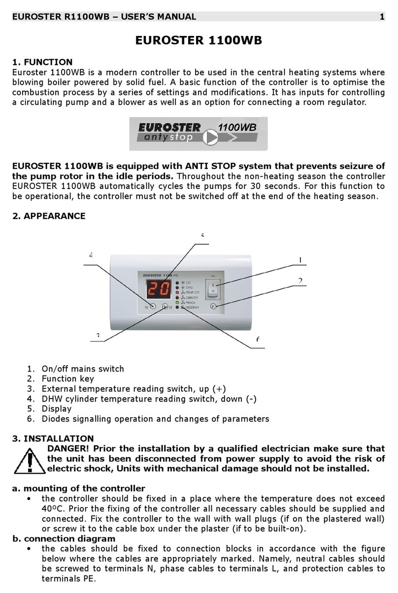
EUROSTER
EUROSTER R1100WB user manual
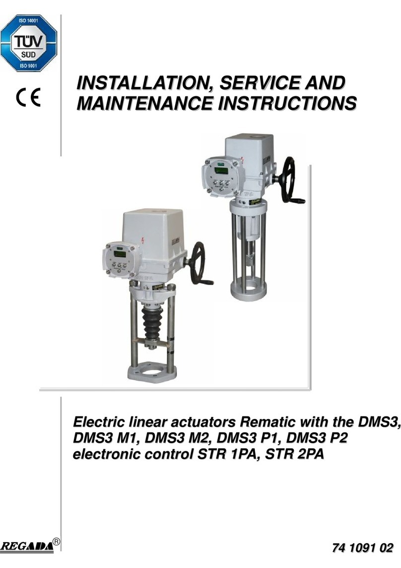
Regada
Regada Rematic STR 1PA Installation, service and maintenance instructions

Conviron
Conviron CMP6050 installation instructions
