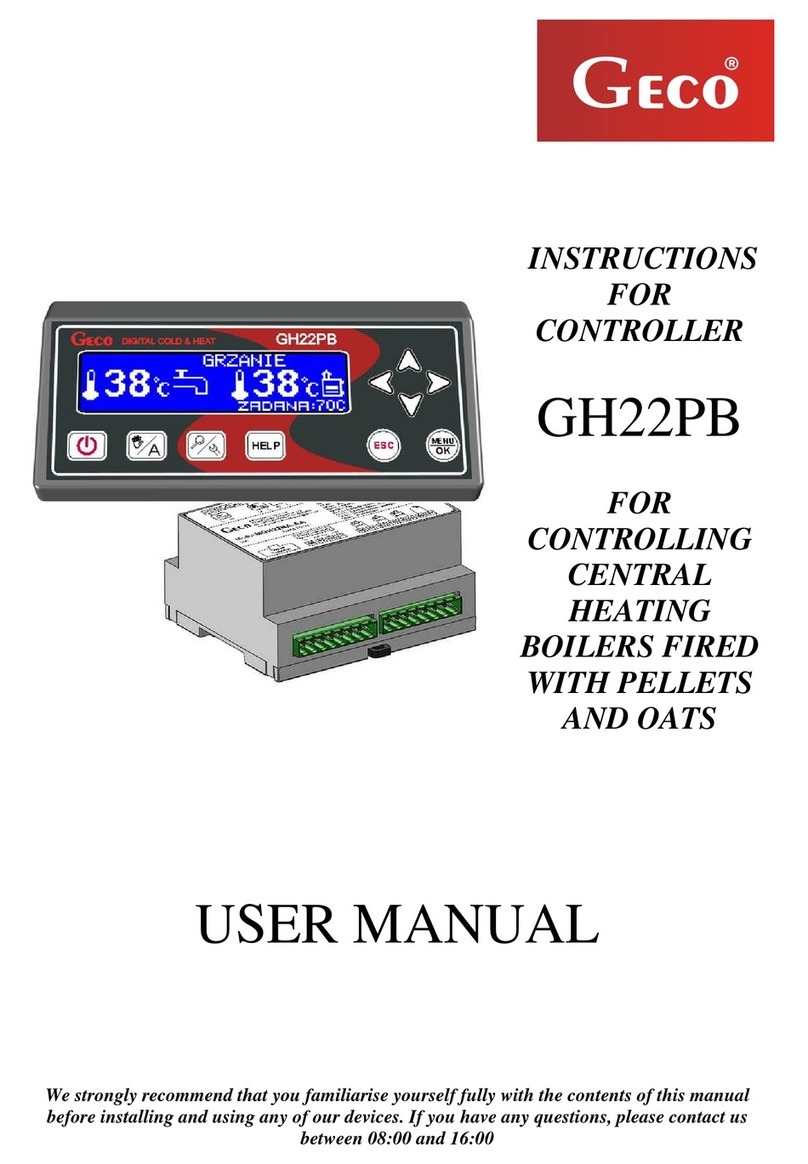
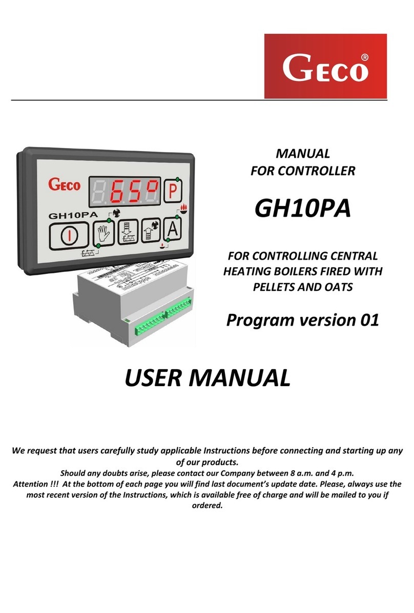
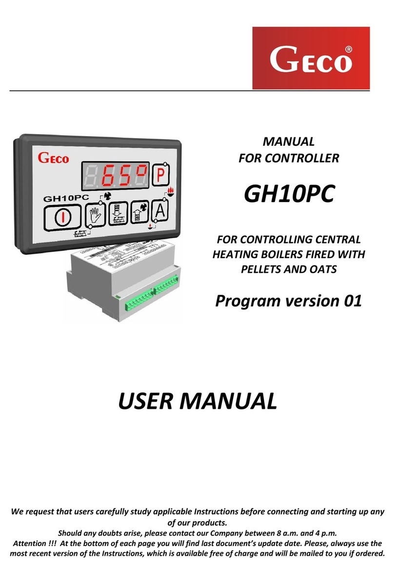
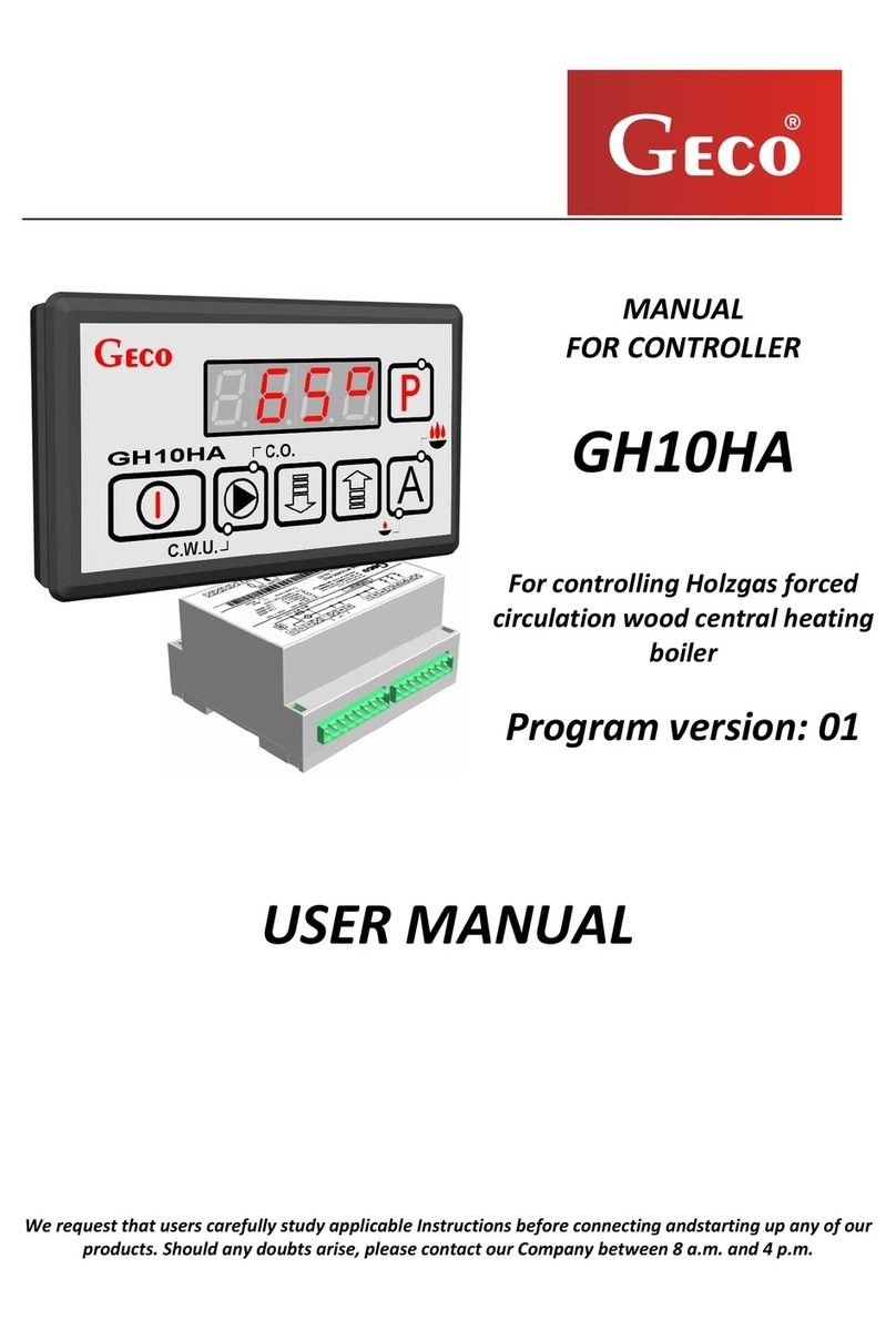
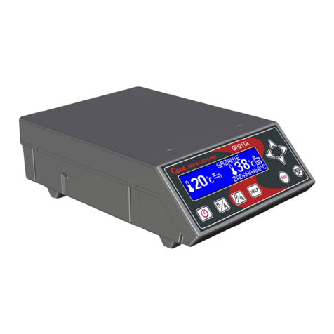
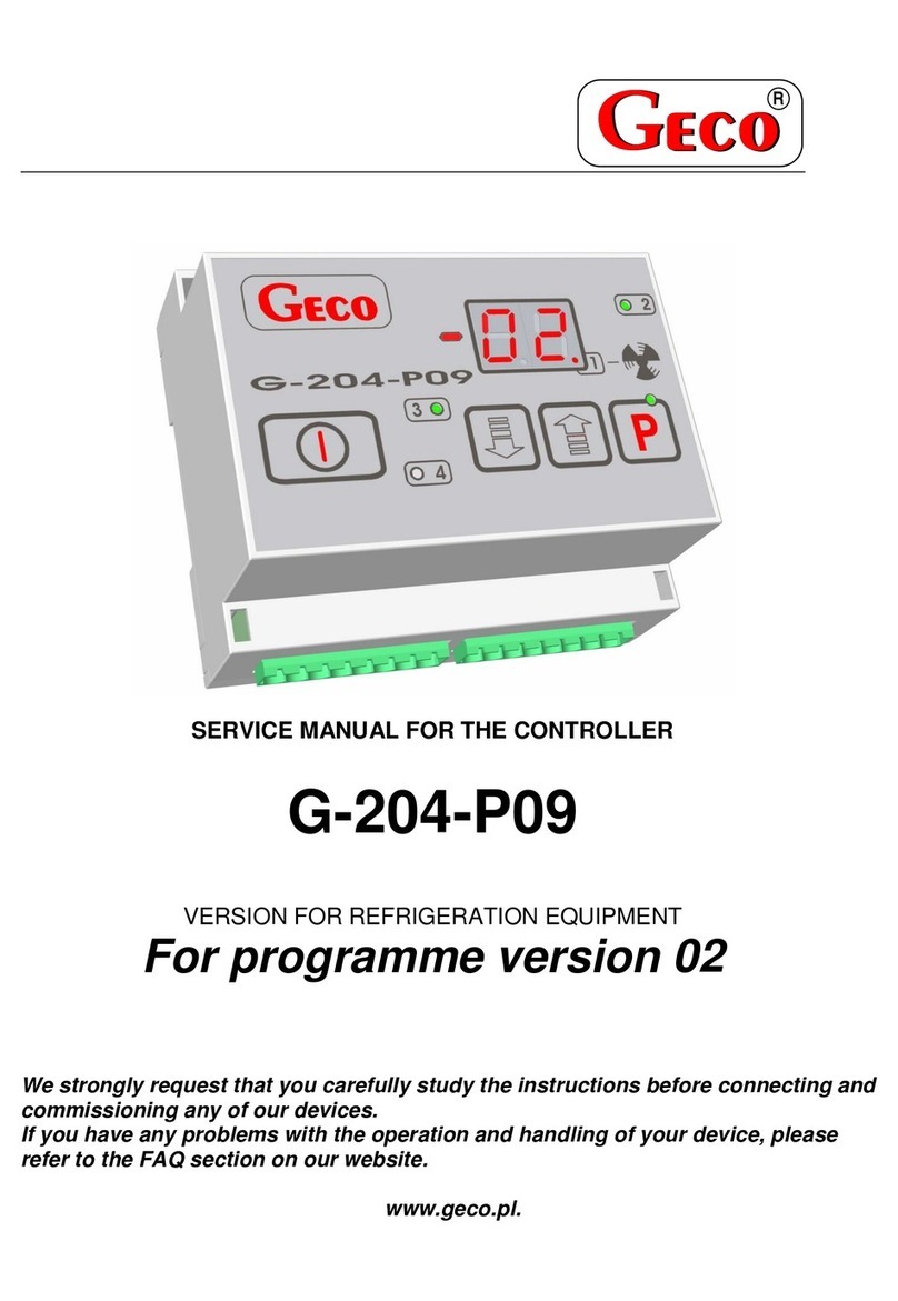
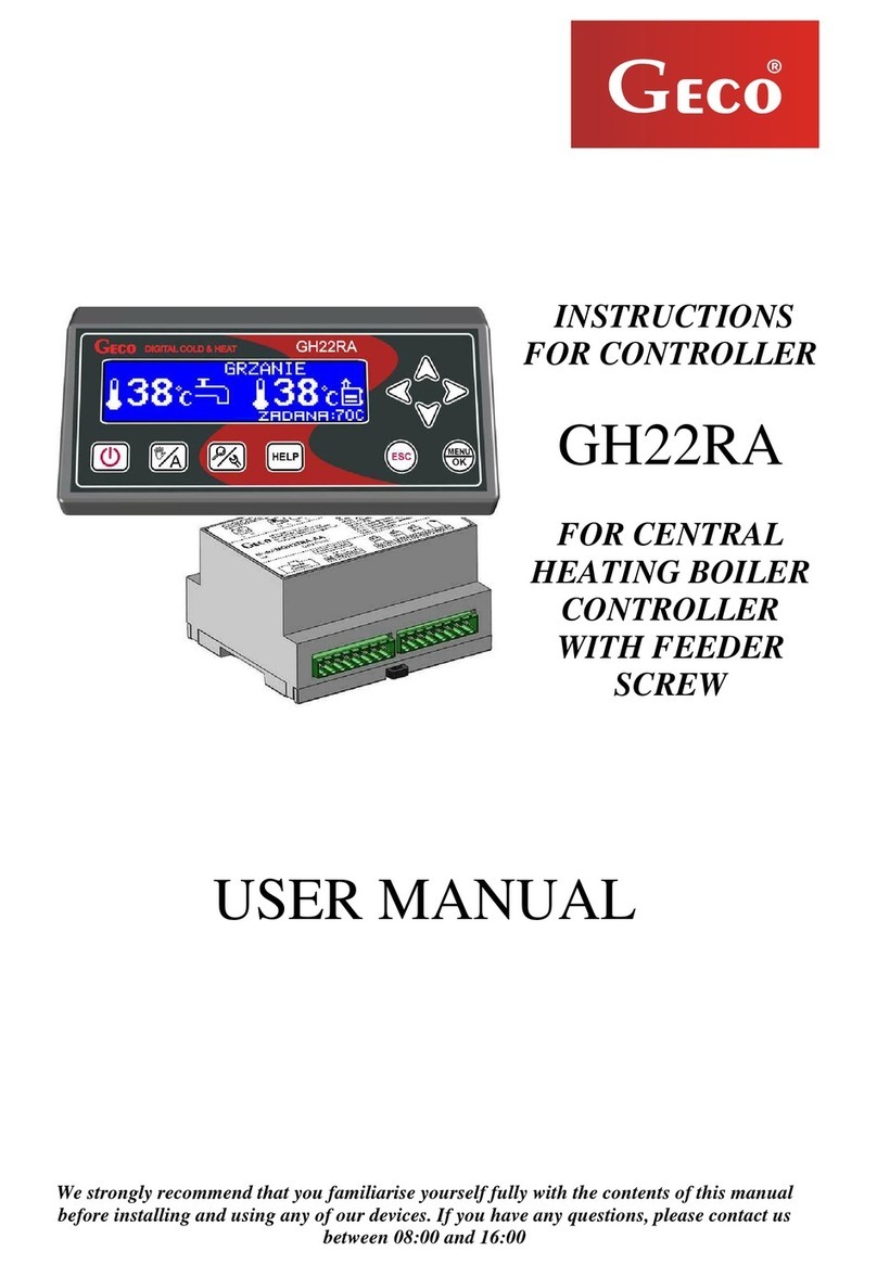
Geco GH11MA User manual

OPERATING INSTRUCTIONS
FOR THE CONTROLLER
GH11MA
TO CONTROL
VENTILATORS
CENTRAL HEATING BOILERS
FOR FINE DUST AND COAL
Version 01
SERVICE MANUAL
We strongly request that you study the instructions carefully before connecting and
commissioning of each of our devices. In case of any doubt, please contact us between 8.00 a.m.
and 4.00 p.m.

SERVICE MANUAL GH11MA PAGE 2
CONTENTS
1. INTRODUCTION ...............................................................................................................................3
1.1. GRAPHIC DESIGNATIONS..................................................................................................................3
1.2. KEYBOARD AND FUNCTION KEYS.....................................................................................................3
2. GENERAL CHARACTERISTICS. ...........................................................................................................4
3. DANE TECHNICZNE ..........................................................................................................................5
4. ELECTRICAL INSTALLATION AND CONNECTION RULES ......................................................................6
5. QUICK START...................................................................................................................................6
6. OBSŁUGA GH11MA..........................................................................................................................8
6.1. HEATING SYSTEM OPERATED...................................................................................................................8
6.2. AUTOMATIC OPERATION MODE ...............................................................................................................9
6.3 MANUAL OPERATION MODE .................................................................................................................10
6.4 TEMPERATURE OVERVIEW ....................................................................................................................10
6.5 ALARMS ............................................................................................................................................11
6.6 SUPPLY VOLTAGE FAILURE ....................................................................................................................11
6.7 BOILER EXPIRY DETECTION....................................................................................................................11
7. USER SETTINGS..............................................................................................................................12
7.2 PRESCRIBED BOILER TEMPERATURE (U0).................................................................................................12
7.3 DHW/RETURN SETPOINT TEMPERATURE (U2).........................................................................................12
7.4 ANTI-LEGIONELLA FUNCTION (U3).........................................................................................................12
8. OPERATION OF THE HOT WATER BOILER........................................................................................ 14
8.2 ASSEMBLY AND CONNECTION................................................................................................................14
8.3 CONFIGURATION OF AUXILIARY PUMP ....................................................................................................14
8.4 DHW PRIORITY ..................................................................................................................................15
8.5 SUMMER MODE..................................................................................................................................15
9. ROOM PANEL ................................................................................................................................15
10. TEMPERATURE LIMITER (STB).....................................................................................................17
SERVICE MANUAL GH11MA PAGE 3
10.2 MODE OF OPERATION ......................................................................................................................17
10.3 STB FUNCTION REACTIVATION (MANUAL) ...........................................................................................17
11. DEALING WITH CONTROLLER DAMAGE.......................................................................................19
12. CONNECTION OF APPLIANCES TO THE GH11MA CONTROLLER.....................................................21
13. INFORMATION ON THE MARKING AND COLLECTION OF WASTE ELECTRICAL AND ELECTRONIC
EQUIPMENT .........................................................................................................................................22
14. SERVICE MODE...........................................................................................................................23
1. INTRODUCTION
1.1. GRAPHIC DESIGNATIONS
Warning
This symbol is used when it is necessary to follow the sequence of operations in the
described instructions. If you make a mistake or do not follow the description, the
device may be damaged or destroyed.
Important!
This symbol indicates information of special interest.
Reference
This symbol indicates the occurrence of additional information in the chapter.
1.2. KEYBOARD AND FUNCTION KEYS
The symbols intended to signal and at the same time emphasise the importance of the text in which the
information on the warning of a dangerous situation is contained have the following graphic form:
PROGRAMMING

SERVICE MANUAL GH11MA PAGE 4
2. GENERAL CHARACTERISTICS.
The GH11MA controller is made using microprocessor technology with automatic surface mounting.
The controller controls the process of preparation of usable hot water (DHW circuit) and enables operation of the
main heating circuit (CH circuit). The control parameters can be adjusted to the current operating conditions and
the type of boiler. The controller is equipped with a system of protection against the effects of power failure and
various types of interference.
The GH11MA controller is equipped with:
Outputs:
1. to measure the temperature of the boiler outlet water (NTC type)
2. to measure the water temperature in the DHW boiler (NTC type - optional)
3. to measure the flue gas temperature (type PT1000 - optional)
input (RS485) for the connection of room panel GA01HA by GECO
It also has three outputs enabling direct connection of 230V devices, i.e.: a fan, central heating circulation pump,
HUW pump or a mixing pump, dependin
ZAŁĄCZ /
WYŁĄCZ
MANUAL ACTIVATION OF
CENTRAL HEATING AND HOT
WATER PUMPS / SIGNALLING
THE OPERATION STATUS OF
THE PUMPS
MANUAL ACTIVATION OF THE CO
/ PARAMETER VALUE CHANGE
UPWARDS
FIRING UP
MANUAL ACTIVATION OF
THE HOT WATER
PUMP/CHANGE OF
PARAMETER VALUES
DOWNWARDS

SERVICE MANUAL GH11MA PAGE 5
THE CONTROLLER SHOULD BE ALWAYS DISCONNECTED FROM
THE MAIN SUPPLY DURING A STORM
3. DANE TECHNICZNE
Supply voltage
230V ~ +10% -15%
Resistance
characteristics of NTC
sensors
Resistance
characteristics of
PT1000 sensors
Working temperature
od +5°C do +40°C
Moisture
od 20% do 80% RH
Temp.
°C
Resistance
Temp.
°C
Resistance
Fan protection
3,15A
0
7174,89
0
1000,00
Sensor type
NTC 2,2kPT
10
4374,83
50
1194,00
Operating range of the
temperature sensor
NTC:
0°C÷100°C
20
2747,10
100
1385,10
PT1000:
0°C÷750°C
30
1774,91
150
1573,30
40
1172,09
200
1758,60
50
795,08
250
1941,00
Output
Maximum
continuous load
60
547,95
300
2120,50
70
384,62
350
2297,20
Pompa CWU / miesz.
1A
200W
80
275,86
400
2470,90
Pompa CO
1A
200W
90
202,37
450
2641,80
Wentylator
1A
200W
100
149,16
500
2809,80
550
2974,90
600
3137,10
650
3296,40
700
3452,80
750
3606,40

SERVICE MANUAL GH11MA PAGE 6
4. ELECTRICAL INSTALLATION AND CONNECTION RULES
1. The boiler room should be equipped with a 230V/50Hz electrical installation in accordance with
the relevant regulations.
2. The electrical installation (irrespective of its type) must be terminated with a plug socket fitted
with a protective contact. The use of a socket without a protective terminal connected risks an
electric shock!!!
3. The controller must be connected to a separately routed power line protected with a suitably
selected fast fuse and a residual current circuit breaker (anti-shock). No other devices may be
connected to this line !!!
THE REGULATOR IS POWERED FROM THE MAINS 230V/50HZ
ANY REPAIRS CAN ONLY BE CARRIED OUT WITH THE POWER SUPPLY
DISCONNECTED AT THE FUSE
5. QUICK START
To start the GH11MA controller, perform the following steps:
1. Connect the unit to the 230V mains supply (insert plug into the socket).
2. Switch on the controller using the button . A screen will appear:

SERVICE MANUAL GH11MA PAGE 7
3. Press the button . The screen will appear:
Controller will start automatic operation based on the factory-set parameters.
Table 1 - Factory settings
Parametr
Parameter description
Min
Max
Step
Factory
setting
U00
Boiler setpoint temperature
’F03’
’F04’
1°C
50°C
U02
Desired DHW temperature / return
35
65
1°C
40°C
U03
Activation of the anti-legionella function
0
1
1
0

SERVICE MANUAL GH11MA PAGE 8
6. OBSŁUGA GH11MA
6.1. Heating system operated
6.2.2 CH + DHW circuit
INPUTS
OUTPUTS
T1 –Boiler temp.
P2 - fan
T3 –DHW temp.
P3 –DHW pump
T6 –Exhaust gas
temp.
P4 –CO pump
6.2.3 CH circuit + mixing pump
INPUTS
OUTPUTS
T1 –Boiler temp.
P2 - fan
T6 –Exhaust gas
temp.
P4 –CO pump
T8 –Return temp.
P8 –mixing pump

SERVICE MANUAL GH11MA PAGE 9
6.2. Automatic operation mode
Pressing the button enters the automatic operation mode of the controller (start of firing-up).
6.2.4 Firing up
The first stage of automatic operation is FIRING-up, which is signalled by the upper indicator light
on the button. .
FIRE-up is automatically terminated when the boiler outlet water temperature reaches U0-F29.
Completion of the firing-up process and exit from it is signalled by lighting up the upper control
light on the button , which remains on during the entire period of the boiler operation in automatic
mode. During the exit from kindling, the fan does not work.
Fire extinguishing during boiler firing up is signalled by displaying message AL 14 on the controller
main screen ( p.6.5 p.11).
This alarm sounds and the firing process is stopped if, after the time set in in service parameter F45
from the moment of start of firing-up the temperature of outlet water from the boiler does not reach the
value F6-4°C.
If it is necessary to burn fuels other than the base fuel, remove
the flue gas temperature sensor from the flue pipe.
(there is a possibility of damaging this sensor) !!!
6.2.5 Fan
In FIRING-UP mode, the fan starts from the minimum speed (gear 1) and increases its speed in
accordance with setting F31, until it reaches the maximum speed set in in service parameter F2.
The fan continues to run until the boiler outlet water temperature reaches the value set in service
parameter F29. Once this value is reached, the fan stops and does not run for approximately 120 seconds.
When the set temperature on the boiler is reached, the fan switches to periodic purging. The duration of
the purge is according to the value set in parameter F26, and the fan operates at its maximum capacity.
These purges take place at intervals set in parameter F27.
Fan activation and operation is indicated by the appearance of a lower vertical line on the controller
display before the temperature measurement.

SERVICE MANUAL GH11MA PAGE 10
6.2.6 CO Pump
In automatic operation mode, the CH pump switches on if the boiler water temperature is greater
than or equal to the value set in service parameter F6 (factory setting is 400C).
The operation of the CH pump is signalled by the upper indicator light on the button
The controller will switch off the pump if the water temperature falls to the pump switch-on temperature
minus 4oC. (If the CH pump switch-on temperature is 400C, then CH pump switch-off temperature is 360C).
6.3 Manual operation mode
Pressing the button switches from automatic to manual operation mode of the controller and
immediately stops the operation of the fan and feeder.
In this operation mode, the user can switch the CH pump and the HUW pump on and off manually and
independently. To do this, follow the diagram below:
ACTIVATION OF THE DOMESTIC HOT WATER PUMP IS
ONLY POSSIBLE IF ITS OPERATION HAS BEEN SELECTED IN
THE SERVICE PAR
6.4 Temperature overview
When the button is activated the display shows the boiler outlet water temperature. Viewing of the flue
gas and DHW/return temperatures is possible in the AUTOMAT and HOLD operating modes, provided that the
flue sensor operation (F11) or the auxiliary pump operation ( p.8.2 p.14) is activated respectively.
To preview the flue gas temperature, press the button . Ponowne wciśnięcie przycisku powoduje wyjście z
podglądu. Wyjście z podglądu następuje również samoczynnie po czasie 10s od momentu naciśnięcia przycisku.
STEP 1
STEP 2
→
i
i
The controller
shows the
measured water
temperature on
the CH boiler
DHW pump
The lower indicator light on the
button lights up .
Pressing the button again
switches off the CH pump and
extinguishes the indicator light.
CO pump
The upper indicator light on
the button lights up .
Pressing the button again
switches off the CH pump and
extinguishes the indicator light.

SERVICE MANUAL GH11MA PAGE 11
Dla uzyskania podglądu temperatury CWU/powrotu należy wcisnąć przycisk . Pressing the button again exits
the preview. Exit from the preview is also automatic 10s after pressing the button.
6.5 Alarms
The controller distinguishes between 7 alarm states. In each of these, the alarm number is displayed and the
acoustic alarm output is activated. If several alarm states occur simultaneously, their numbers are displayed
cyclically. Exit from an alarm state is only possible by pressing the button . Types of alarms:
AL1
STB tripped or fuse blown
AL2
Failure of the boiler outlet water temperature sensor
AL4
Failure of the DHW/return temperature sensor
AL7
Flue gas temperature sensor defective
AL12
Flue gas temperature sensor defective
AL13
Expiration of the boiler
AL14
Firing failure (expiration in firing-up)
6.6 Supply voltage failure
After a power failure, the controller will take action depending on the state it was in before the power
failure. The controller waits for 1 minute for the state of the power supply to stabilise and then returns to
operation with the previously programmed parameter values.
During the waiting time, the display shows the time remaining in seconds
during the wait, the display indicates the time in seconds remaining and the status of the controller
before the power failure:
The flashing letter "A" corresponds to automatic operation,
the letter "P" corresponds to sustained,
letter 'r' of manual work.
6.7 Boiler expiry detection.
If, during automatic operation for the time set in parameter F9, the boiler outlet water temperature is
below the value set in parameter F8, the controller considers that the boiler has expired and AL 13 is
reported.
If, during automatic operation, for the time set in parameter F9, the flue temperature is below the
value set in parameter F11, the controller considers the boiler extinguished and AL 13 is reported.
If F11=0, this detection after the chimney temperature is disabled.

SERVICE MANUAL GH11MA PAGE 12
7. USER SETTINGS
7.2 Prescribed boiler temperature (u0)
The boiler temperature setpoint is changed as follows:
7.3 DHW/return setpoint temperature (u2)
This parameter is available to the user only if he/she uses the
using the domestic hot water (DHW) heating option or return temperature stabilisation option, and has
configured the auxiliary pump by setting the value of service parameter F00 to "1" , "2" , "3" or "4". (
p.8.2 p.14).
Modification of this parameter is carried out in the same way as described in p.7.1
and p.7.2.
7.4 Anti-Legionella function (u3)
The GH11MA controller is equipped with an ANTI-LEGIONELLA function to limit the growth of
Legionella pneumophilia bacteria in the hot water system. This function is only available to the user when
parameter F00 is set to "2" , "3" or "4" ( p.8.2 p.14).
STEP 1
STEP 2
STEP 3
→
lub
→
The green LED on the
button lights up.
The display shows the
temperature set so far
Setting the desired
temperature from
50C to 85C
Storage
New temperature
value.
Move to parameter u1
If, when setting a new temperature for 15 seconds no key is
pressed , , ,
then the new temperature will not be memorised and the
controller will exit programming mode.

SERVICE MANUAL GH11MA PAGE 13
Legionella bacteria thrive in an aqueous environment, with an optimum in temperatures of 38-420C. The
growth of these bacteria is also favoured by stagnant hot water in plumbing systems, hot water heaters
and DHW cylinders
Legionella bacteria cause a non-specific form of pneumonia known as Legionnaires' disease, or
Legionellosis. Legionellosis has been officially recognised by the Ministry of Health as an infectious disease.
The ANTI-LEGIONELLA function implemented by the GH11MA controller to ensure the creation of a
conditions in the domestic hot water system (DHW tank) such that the Legionella bacteria do not find
favourable living conditions.
In order to activate the ANTI-LEGIONELLA function, parameter u6 should be set to value 1.
Activation of this function and its duration is indicated by the flashing "L" on the left-hand side of the
display, before the displayed temperature value.
Deactivation of this function is possible by setting the parameter u3=0 or by pressing the button .
The Anti-Legionella function also stops after a power failure.
The ANTI-LEGIONELLA function is an overriding function, which means that it is performed by the
controller first (priority function).
When this function is activated, the boiler water temperature is raised to 70C
and is maintained for a period of 10 minutes.
ACTIVATING THE ANTI-LEGIONELLA FUNCTION INCREASES THE HOT
WATER TEMPERATURE TO 700C.
TAKE SPECIAL CARE WHEN USING HOT WATER.
MAY CAUSE BURNS !!!

SERVICE MANUAL GH11MA PAGE 14
8. OPERATION OF THE HOT WATER BOILER
The GH11MA controller makes it possible to connect an additional pump to control the heating of
domestic hot water (DHW) in the boiler.
8.2 Assembly and connection
If you wish to use the domestic hot water (DHW) heating option, carry out the following steps:
1. connect the boiler according to the enclosed diagram ( p.6.1.1 p.8).
2. place the DHW temperature sensor inside the boiler
It is recommended to install the DHW temperature sensor in the
measuring wells of "GECO" Ltd.
It is absolutely forbidden to place temperature sensors in wells with
oil or other liquid !!!
3. connect the HUW temperature sensor to the controller under the terminals as
shown in Fig. 2.
4. configure the operation of the DHW pump ( p.8.2 p.14).
8.3 Configuration of auxiliary pump
his parameter enables the user to switch on the operation of an additional pump, which can be a mixing
pump or a DHW pump operating with or without priority.
The HUW pump is activated when the boiler outlet water temperature is higher than 40C
and higher than the boiler water temperature (in order not to cool down the HUW boiler), and the boiler
temperature is lower than the one set by the user in parameter u2 ( p.7.3 p.12).
The pump operation is signalled by a dot next to the fan symbol on the display.
The HUW temperature sensor is an additional sensor (option), not
supplied together with the GH11MA controller.
It is possible to purchase the aforementioned sensor for an additional
charge from the manufacturer, i.e. "GECO" Sp. z o.o.

SERVICE MANUAL GH11MA PAGE 15
In the case of the boiler room configuration as presented in the diagram ( p.6.1.1 p.8), the boiler
controller does not have an external alarm output, but has the possibility to view the HUW boiler
temperature.
Aby załączyć w sterowniku obsługę dodatkowej pompy należy postepować następująco:
STEP 1
STEP 2
STEP 3
STEP 4
→
→
lub
→
The display
shows
„─ ─ ─ ─”
Hold
for 2s
Set the desired value for parameter F00
0–no pump operation
1–mixing pump
2–DHW pump winter without priority
3–Winter HUW pump with priority
4–DHW pump summer mode
Remembering
new
value
8.4 DHW priority
It is possible to set the operation of the DHW pump in priority mode on the GH11MA controller. If you
select such a mode of operation of the DHW pump, DHW heating becomes the overriding function in the
controller.
To do this, set the value "3" of service parameter F00.
8.5 Summer mode
The GH11MA controller is equipped with the so-called SUMMER MODE, with the use of which the CH
pump can be switched off for the summer period and the boiler operates only for the needs of hot utility
water CWU.
To do this, set the value "4" in the F00 service parameter.
9. Room Panel
The GH11MA regulator has been adapted for full communication with the GA01HA room panel from
GECO, enabling comfortable supervision of boiler operation from the flat.
The GA01HA room panel connected to the GH11MA controller allows:
change of the preset boiler temperature (u0)
change of DHW set temperature (u2)
display of all alarms on the room panel
view of the operating status of the boiler
viewing the operating status of devices (fan, CH pump, DHW pump)

SERVICE MANUAL GH11MA PAGE 16
preview of all measured temperatures
If a GA01HA room panel is correctly connected to the GH11MA controller, it will be automatically detected
by the controller and no further action or settings by the user are required.
In this situation, the controller operates according to the settings set by the room panel.
Disconnection of the room panel (interruption of communication) or damage to the cable connecting the
panel with the controller is manifested by lighting of a dot on the last display after the time of 30s from the
disconnection of the panel.
In order to connect the GA01HA room panel to the GH11MA controller, it is necessary to:
STEP 1
STEP 2
STEP 3
STEP 4
STEP 5
Switch off the
controller with
the button
and unplug the
mains cord
from the
socket.
→
Open the
controller
(remove the
top cover of
the housing)
→
Connect the
room panel to
the controller
at terminals
A-B-C-D as
shown in Fig.
1.
→
Snap on the
top cover of
the controller
housing (close
the
controller)
→
Insert the mains plug
into the 230V socket
and switch on the
controller with the
GH11MA GA01HA-01
Connection diagram of room panel GA01HA to GH11MA controller
THAT THE CONTROLLER OPERATES ACCORDING TO THE ROOM PANEL
SETTINGS IS INDICATED BY THE LIGHTING OF THE DOT ON THE LAST
DISPLAY

SERVICE MANUAL GH11MA PAGE 17
10. TEMPERATURE LIMITER (STB)
The GH11MA controller is equipped with an additional mechanical protection device, independent of
the automation, called a safety temperature limiter (STB).
10.2 Mode of operation
If the heating water reaches a temperature of 950Cthe temperature limiter will operate automatically
(activates the STB function) and interrupt the combustion air supply (switches off the fan).
When the temperature at the limiter drops by approximately 200Cit will be possible to switch on the
STB function again, only manually.
10.3 STB function reactivation (manual)
To restart the unit, press the "RESET" button located on the left side of the controller housing.
For safety reasons, the controller does not automatically revert to automatic operation.
For the controller to return to operation, press the button twice :
- First press of a button clears the alarm and switches off the controller
- Second press of the button restarts the controller
- Press - the controller switches to automatic operation mode

SERVICE MANUAL GH11MA PAGE 18
PUNCTURE OR BREAKAGE OF THE CAPILLARY INDICATES A LEAKAGE
OF THE TEMPERATURE LIMITER FILLED WITH LIQUID, WHICH LEADS
TO MALFUNCTION OF THE GH11MA CONTROLLER.
IF THE DESCRIBED MALFUNCTION IS DETECTED, THE TEMPERATURE
LIMITER SHOULD BE DISCONNECTED FROM THE GH11MA
CONTROLLER, REMOVED AND REPLACED WITH A NEW UNIT.

SERVICE MANUAL GH11MA PAGE 19
11. DEALING WITH CONTROLLER DAMAGE
If you notice any malfunctions in the controller, it is advisable to contact the boiler
supplier/manufacturer or GECO Ltd.
Expert technical advice will be provided there.
If a service action to repair the controller is required, the defective controller must be removed from the
boiler and the complete controller, including the casing, sent to the address indicated.
SENDING AN INCOMPLETE CONTROLLER TO THE SERVICE CENTRE
AUTOMATICALLY VOIDS THE WARRANTY.
PREPARING THE CONTROLLER FOR SERVICE
STEP 1
Disconnect the controller
from supply voltage
(remove plug from socket)
STEP 2
Remove the front panel
using
flat screwdriver

SERVICE MANUAL GH11MA PAGE 20
KROK 3
Remove the housing cover
by undermining the latches
using
flat screwdriver
KROK 4
Remove the plug connectors with the
connected wires from the sockets,
unscrew the earth wires from the PE
strip, loosen the wire clamping strip and
remove all the wires outside the
controller
KROK 5
Remove the controller from the boiler by
unscrewing the 4 mounting screws
on the lower part of the
casing of the controller
KROK 6
Attach the top cover of the housing
and front panel
Table of contents
Other Geco Controllers manuals
Popular Controllers manuals by other brands

e-con Systems
e-con Systems See3CAM CX3RDK Series Application User's Manual

SpaNet
SpaNet SV Series quick start guide

Bosch
Bosch Buderus Logamatic 5000 Series Guideline

RBM
RBM RinoxPlus M Technical sheet

Victron energy
Victron energy BlueSolar PWM-Light 12/24-5 manual

Mitsubishi Electric
Mitsubishi Electric MELSEC iQ-R Series user manual

Siemens
Siemens SSA Series Mounting instructions

Linear Technology
Linear Technology LTC4365 Demo Manual

Dirt Devil
Dirt Devil M024 Series operating manual

Süd wind
Süd wind ambientika WallPanel manual

3One data
3One data IAP2300C Series Quick installation guide

United CoolAir
United CoolAir MARVEL MINI Installation, operation and maintenance manual