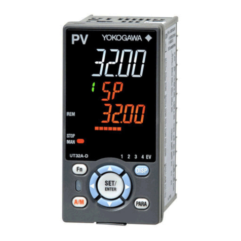
EUROSTER R1100WB User manual

EUROSTER R1100WB – USER’S MANUAL 1
EUROSTER 1100WB
1. FUNCTION
Euroster 1100WB is a modern controller to be used in the central heating systems where
blowing boiler powered by solid fuel. A basic function of the controller is to optimise the
combustion process by a series of settings and modifications. It has inputs for controlling
a circulating pump and a blower as well as an option for connecting a room regulator.
EUROSTER 1100WB is equipped with ANTI STO system that prevents seizure of
the pump rotor in the idle periods. Throughout the non-heating season the controller
E ROSTER 1100WB automatically cycles the pumps for 30 seconds. For this function to
be operational, the controller must not be switched off at the end of the heating season.
2. A EARANCE
1. On/off mains switch
2. Function key
3. External temperature reading switch, up (+)
4. DHW cylinder temperature reading switch, down (-)
5. Display
6. Diodes signalling operation and changes of parameters
3. INSTALLATION
DANGER! rior the installation by a qualified electrician make sure that
the unit has been disconnected from power supply to avoid the risk of
electric shock, Units with mechanical damage should not be installed.
a. mounting of the controller
•the controller should be fixed in a place where the temperature does not exceed
40ºC. Prior the fixing of the controller all necessary cables should be supplied and
connected. Fix the controller to the wall with wall plugs (if on the plastered wall)
or screw it to the cable box under the plaster (if to be built-on).
b. connection diagram
•the cables should be fixed to connection blocks in accordance with the figure
below where the cables are appropriately marked. Namely, neutral cables should
be screwed to terminals N, phase cables to terminals L, and protection cables to
terminals PE.

EUROSTER R1100WB – USER’S MANUAL 2
•if a room regulator is to be connected, a cramp should be removed from RP
connection box and in this place the cables for the room regulator should be
connected (recommended cable: 2x0.5).
4. O ERATION AND ROGRAMMING
a. start up of the controller
•set the switch (~) to position I,
•upon energizing all the segments and light emitting diodes of the display light up
for 3 seconds and an acoustic signal (buzzer) activates.
•the current temperature of central heating sensor is displayed and the controller
switches to the heating mode.
b. description of displayed information
•lack of lit dots on the display – central heating temperature shown
•lit dot after the first digit – DHW temperature shown
•lit dot after the second digit – the external temperature shown
•central heating diode (CO) on – signal of the central heating pump in operation
•DHW diode (CW ) on – signal of the DHW pump in operation
•central heating temperature diode on (TEMP.CO) – signal of the blower in
operation
•blinking display and a sequence of light emitting diodes – parameter changing
modes
c. change of temperatures central heating and domestic hot water
setting the temperature for central heating pump
•press the function key (F) – the diode signalling the setting for central heating will
start blinking.
•set a required temperature buy using switches (+) to increase or
(-) to decrease the displayed temperature
•wait ca. 5 seconds until the preset temperature has been stored and they display
will return to displaying the current temperature of the central heating sensor
setting the temperature for DHW pump
•press the function key (F) until the diode signalling the setting for DHW will start
blinking
•set a required temperature buy using switches (+) to increase or
(-) to decrease the displayed temperature
•wait ca. 5 seconds until the preset temperature has been stored and they display
will return to displaying the current temperature of the central heating sensor

EUROSTER R1100WB – USER’S MANUAL 3
d. viewing the outside temperature
•in order to display the outside temperature press the switch TZ (+). The display
will show the current temperature of the outside temperature sensor (with a dot
after the second digit).
e. viewing the temperature of the DHW cylinder
•in order to display the temperature of the cylinder press the switch TB (-). The
display will show the current temperature of DHW cylinder sensor (with a dot after
the first digit).
f. adjusting the temperature of the blower
setting the temperature of the blower for outside temperature at +10ºC
•press the function key (F) until the diode TEMP CO will start blinking and the
display will show the required temperature with a dot after the first digit
•set a required temperature buy using switches (+) to increase or
(-) to decrease the displayed temperature
•wait ca. 5 seconds until the preset temperature has been stored and they display
will return to displaying the current temperature of the central heating sensor
setting the temperature of the blower for outside temperature at -20ºC
•press the function key (F) until the diode TEMP CO will start blinking and the
display will show the required temperature with a dot after the second digit
•set a required temperature buy using switches (+) to increase or
(-) to decrease the displayed temperature
•wait ca. 5 seconds until the preset temperature has been stored and they display
will return to displaying the current temperature of the central heating sensor
ATTENTION!
Due to the modus operandi of the weather algorithm the preset temperature for
-20ºC cannot be set below the temperature below the preset temperature of
+10ºC.
g. setting the blower rotations
•press the function key (F) until the diode OBROTY will start blinking. Switches (+)
and (–) change the value of the setting code and set a required value of the
blower rotations. Blinking digits show a code from 0 to 9 which determines the
value of the blower rotations settings in operation. Depending on the needs the
force of blowing is determined with the use of this parameter ranging from 0 to 9,
where 0 means MAXIMAL and 1 - MINIMAL rotations of the blower.
h. blowing time adjustment
•press the function key (F) until the diode PRACA will start blinking and the display
will show a code from 0 to 9 which determines the time value of current setting in
accordance with the table below.
•set the cyclic blowing – right switch (extending) or left switch (shortening)
•wait ca. 5 seconds until the setting has been stored and the display will show the
current temperature will show the current temperature of the central heating
sensor
i. blowing interval adjustment
•press the function key (F) until the diode PRZERWY starts blinking and the display
shows a code from 0 to 9 which determines the time value of current setting in
accordance with the table below.
•set the blowing interval – right switch (extending) or left switch (shortening)
•wait ca. 5 seconds until the setting has been stored and the display will show the
current temperature will show the current temperature of the central heating
sensor

EUROSTER R1100WB – USER’S MANUAL 4
CYCLIC BLOWING TIME
CODE 0 1 2 3 4 5 6 7 8 9
TIME Off 5s 10s 15s 20s 30s 40s 60s 80s 100s
CYCLIC BLOWING INTERVAL
CODE 0 1 2 3 4 5 6 7 8 9
TIME 20s 1min 2min 4min 6min 8min 10min 12min 14min 16min
5. O ERATION OF THE CONTROLLER
a. mode: heating and cooling
•E1100WB is equipped with the heating function that is activated by the on/off
mains switch. This function is operational just after switching on the controller.
The controller checks the temperature of water in the boiler and when due to the
heating the temperature of the central heating sensor reaches the preset
temperature for the blower (the value preset for +10°C), the heating function will
be switched off and the controller will start its operation in accordance with the
settings. During the heating mode the controller does not receive information
from the external input (room regulator) and does not activate the pumps,
whereas the blower operates according to the user’s settings. When the
temperature in the boiler does not increase above 30ºC for 60 minutes, then the
controller will switch off the blower and activate the sound alarm for 20 minutes
(the furnace has cooled down). Another increase of temperature will cause the
blower to activate (heating) and operate according the user’s settings.
b. mode: controlling
•After heating up the boiler the controlling mode starts when the controller
operates according to the settings. Central heating pump is activated when the
temperature of the central heating sensor reaches the preset temperature. The
pump will be switched off if the temperature falls below the value set by 5ºC. Due
to activated DHW priority the central heating pump will be operational only when
the DHW pump is switched on.
The blower is activated when the temperature in the boiler decreases below the
preset temperature. In case when the temperature of the sensor reaches the
preset temperature, then the controller reduces its rotations every second until a
compete stop. When the measured temperature is above the preset temperature
then the process of cyclic activation of the blower will start in order to blow the
furnace. When exceeding the temperature of 85ºC the process of furnace blowing
will be inactive and the controller will start the alarm mode, absolutely activate
the central heating pump and start the acoustic signal (buzzer).
c. controlling the DHW pump and operation according to the priority
•Euroster 1100WB has a priority of heating DHW with a function of protecting the
DHW cylinder against cooling. During heating up the cylinder the controller does
not receive information from the room regulator and in this situation it will try to
heat the cylinder as soon as possible. Irrespective of other algorithms the blower
temperature will be automatically increased by 10ºC above the temperature
preset for the DHW pump. The pump is activated if the temperature of the
cylinder sensor is below the setting and the central heating temperature is 10ºC
above the current temperature of the DHW sensor. If the temperature increases
and reaches the preset temperature for the cylinder or when the temperature of
central heating sensor is equal or below the current temperature of the DHW
sensor, then the pump is switched off.

EUROSTER R1100WB – USER’S MANUAL 5
d. weather controlling
•The algorithm of controlling the blower has two separate setting temperatures
(the preset temperature of the blower for the external temperatures of: +10ºC
and -20ºC) which are used by the internal room regulator when determining the
current temperature of the blower in operation. With the use of these two settings
the controller determines the heating curve shown below.
ATTENTION !
In order to switch off the weather regulator, the same values should be set for
both settings.
Dependence of the current temperature of blower operation on the temperature outside.
e. room regulator
•The controller is equipped with an input for a room regulator. If the regulator
requires heat (shorted contacts), it means that the boiler is to operate and heat
up – the central heating pump and the blower operate according to the user’s
settings in order to maintain the preset temperature. Whereas when there is not
need for heat (opened contacts), the controller modifies the settings in order to
maintain the boiler temperature at 40ºC. The algorithm of the ventilator operates
with the preset temperature of 40ºC, cyclic blowings are active and the central
heating pump is activated.
f. operation without the DHW pump
•When a user is not going to use the function of heating the DHW, then in the place
of a DHW temperature sensor resistor at a value of 2,2 kΩ (included in the set)
should be mounted and set the temperature of the DHW pump at the minimal
value (eliminates the DHW priority function).
g. operation during the non-heating season
•In order to switch of the central heating during the non-heating season, the
temperature for the central heating pump should be set at 90ºC (above the
setting for DHW and the blower) and then only the cylinder will be heated. The
temperature set for the blower will be automatically increased by 10ºC above the
preset temperature for the DHW pump so that cylinder will be heated as fast as
possible.

EUROSTER R1100WB – USER’S MANUAL 6
6. STANDARDS AND CERTIFICATES
The Controller E1100WB is made in compliance with the following E Directives: EMC,
LVD.
The CE certificate of conformity is posted and available on our website:
www.euroster.com.pl
7. DATA SHEET
a. temperature setting range for DHW pump:10ºC - 70ºC
b. temperature setting range for central heating pump:10ºC - 90ºC
c. temperature setting range for the blower: 40ºC - 80ºC
d. supply voltage: ~230V
e. maximum power of the blower: 150W
f. maximum loading of the pumps: 6A
g. external temperature measurement: -30ºC to +99ºC
h. central heating and DHW temperature measurement: 0ºC - 99ºC
i. heating hysteresis: 5ºC
j. DHW hysteresis: 3ºC
8. ERROR CODES
a. displayed:
•C2 – incorrectly connected sensor, stoppage
•C1 – incorrectly connected sensor, short circuit
•EE – stored temperature reading error
•dd – internal error
b. acoustic (buzzer):
•emergency situation (error) – quick broken signal
•dangerous temperature of 85ºC reached (central heating) – continuous signal
•furnace cooling – continuous signal for 20 minutes
9. Exemplary wiring diagram
This diagram is simplifies and as such does not show all the components necessary for
fully functional operation of the system.
1. Heating boiler
2. Hot water cylinder
3. Shutoff valve
4. Filter screen
5. Central heating pump
6. Check valve
7. Heating unit
8. Central heating temperature sensor
9. Controller
10. Heating water circulating pump
11. DHW temperature sensor
12. External temperature sensor
13. Blower
14. Room regulator
Table of contents
Other EUROSTER Controllers manuals
EUROSTER
EUROSTER 1100K User manual
EUROSTER
EUROSTER 11Z User manual
EUROSTER
EUROSTER 11WB User manual

EUROSTER
EUROSTER 11Z User manual
EUROSTER
EUROSTER 813 User manual
EUROSTER
EUROSTER 12M User manual
EUROSTER
EUROSTER 11W User manual

EUROSTER
EUROSTER UNI3 User manual
EUROSTER
EUROSTER 11M User manual
EUROSTER
EUROSTER 10PC User manual

EUROSTER
EUROSTER 11WB User manual

EUROSTER
EUROSTER 11 User manual
EUROSTER
EUROSTER UNI2 User manual

EUROSTER
EUROSTER 11E User manual
EUROSTER
EUROSTER FH1 User manual
EUROSTER
EUROSTER 11B User manual

EUROSTER
EUROSTER 11K User manual

EUROSTER
EUROSTER 11W User manual

EUROSTER
EUROSTER 1100E User manual
EUROSTER
EUROSTER UNI4 User manual
