BM PRO TrailCheck User manual

TEAMBMPRO.COM
OWNER’S MANUAL
TrailCheck

TEAM
BMPRO
.COM
POWERING YOUR ADVENTURES
With over 50 years’ experience in
power solutions combined with
manufacturing and design facilities in
Melbourne, Australia, BMPRO are the
leading experts in RV power and control
management.
Inspired by the great outdoors, we
have created a range of rugged, smart
and reliable products to power your
adventures.
Our range of battery, power and RV
management and control systems gives
you peace of mind when you are on the
road, so that you can relax in even the
most far flung destinations, knowing
you have control over your power
needs.
To learn more about the BMPRO range
of products, please visit our website
teambmpro.com
2

CONTENTS
ABOUT TRAILCHECK 4
Key Features 4
What’s Included 4
TRAILCHECK MONITOR INSTALLATION INSTRUCTIONS 4
Pairing the TrailCheck to the TrailSafe Series 5
TrailCheck Status Indicator 6
SERVICING 9
SPECIFICATIONS 9
WARRANTY TERMS AND CONDITIONS 10
Copyright © 2019
MANUAL PART 034614
REV 1.0
Designed by BMPRO, one of Australia’s leading power solution experts, the BMPRO range of
products are proudly Australian-Made in Melbourne, Victoria and represent a high-quality
product that will provide years of service.
DISCLAIMER: BMPRO accepts no liability for any loss or damage which may occur from
the improper or unsafe use of its products. Warranty is only valid if the unit has not been
modified or misused by the customer.
3

ABOUT TRAILCHECK
TrailCheck is a wireless in-car monitor of towing safety equipment, which enables
the status monitoring of:
1. BMPRO TrailSafe - emergency trailer breakaway safety system
2. BMPRO SwayControl - proactive electronic stability control (ESC) sway control
system
The TrailCheck will indicate system status with BLUE, GREEN, ORANGE or RED LED
indicators.
KEY FEATURES
9Bluetooth connectivity.
9LED status indicators for full-system safety check.
9If paired with TrailSafe+ and SwayControl, forms the TowControl, an integrated
towing safety system with in-car reporting.
WHAT’S INCLUDED
Included with this product are:
9TrailCheck
9TrailCheck manual
9Velcro strips
TRAILCHECK MONITOR
INSTALLATION INSTRUCTIONS
The monitor should be located so that it is visible to the driver. Confirm operation by
pressing the brake pedal and viewing the battery status indicated.
With the wireless TrailCheck, some location options may provide a more reliable
connection. If a suitable location can’t be found, a wired remote is required.
TrailCheck can be mounted with the provided Velcro strips and plugs into a 15A
(or lower) fused vehicle 12VDC accessory socket. Ensure the TrailCheck will not
dislodge during severe braking.
Recommended location is on the side of the transmission tunnel or under dash. Make
sure the surface is free from dust and grease to ensure good adhesion.
4

Apply the hook Velcro to the TrailCheck on the side to be attached to the vehicle by
peeling off the clear tape.
Similarly attach the loop side Velcro to the vehicle where it will be mounted so that
the tapes will align.
Ideally clean the surface with isopropyl (rubbing) alcohol and leave for 24 hours
to achieve maximum adhesion before mounting the TrailCheck.
Avoid contacting the tape with fingers.
After completing installation of the TrailCheck, conduct a trial operation to check
for faults.
Test with the engine running. If there is too much metal between the TrailSafe series
or SwayControl and TrailCheck or a high level of electrical noise in the vehicle,
TrailCheck may not provide an adequate connection.
PAIRING THE TRAILCHECK TO THE TRAILSAFE SERIES.
To pair the TrailSafe series to the TrailCheck and enable system monitoring from the
TrailCheck, perform the following:
1. Complete wiring of the TrailSafe System and confirm that the battery indication is
working when the Pull Pin is removed.
2. Insert the Pull Pin
3. Power the TrailCheck by inserting the power connection into the vehicles 12VDC
accessory socket and turn on the ignition.
4. Press the button on the rear of the TrailCheck for 1 second confirming the Status
Indication is flashing BLUE
5. Operate the brake pedal and watch the TrailCheck Status indicator for up to 2
minutes.
a. If the TrailCheck Status indicator turns solid BLUE for 2 seconds then pairing to
the TrailSafe was successfully. The TrailCheck Status indicator will then show
either solid GREEN, solid ORANGE or solid RED. See the TrailCheck Status
indicator output descriptions.
b. If the TrailCheck Status indicator changes to flashing ORANGE then pairing
failed. Return to step 4 to try again.
If pairing does not work try an alternate location for the TrailCheck. Pairing can be
cleared by pressing and holding the button on the rear of the TrailCheck until the
Status Indication starts flashing ORANGE (approximately 5 seconds)
The TrailCheck can be unplugged when not in use and will not require repeating the
pairing sequence when reused.
5
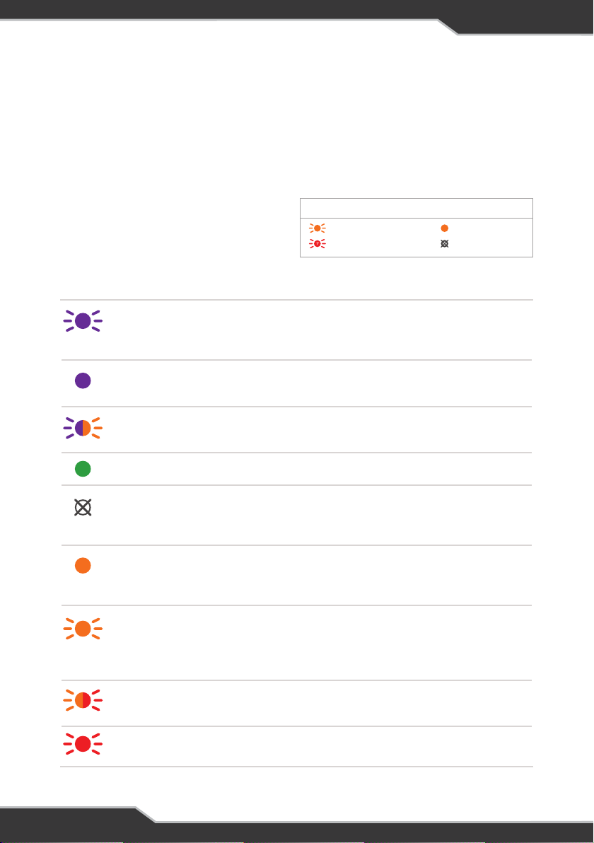
TrailSafe / TrailSafe+
in calibration
1. Wait until LED goes solid PURPLE.
2. If occurring after removing pull-pin, wait until
indicator changes then put pull-pin back in.
Completed 1st or 2nd
calibration stage
If pin is in when Solid PURPLE, remove pin; if pin
is out when Solid PURPLE, put pin back in.
Pull-pin removed before
calibration stage completed
Put pull pin back in to restart.
House battery capacity sufficient for 15mins of emergency braking operation
TrailSafe / TrailSafe+ or
TrailCheck standby or no power
If necessary, check TrailSafe / TrailSafe+
by depressing brake. Check if TrailCheck
connected to power source.
House battery may have
insufficient capacity for 15mins
emergency braking operation
Check battery to ensure at least 10Ah house
battery capacity available.
TrailSafe / TrailSafe+in
standby and battery may have
insufficient capacity for 15mins
emergency braking operation
Check battery to ensure over 10Ah house
battery capacity available.
TrailSafe / TrailSafe+breakaway
switch leaky or corroded
Do not use unit. Replace unit.
Pin out or trailer breakaway
CONDITIONSTATUS SOLUTION
TRAILCHECK STATUS INDICATOR
Correct operation of TrailSafe and SwayControl should be checked prior to each
use of the trailer. This check should be done prior to the trailer being hitched to the
towing vehicle. TrailSafe can be checked by depressing brake or pulling out the
safety pin. This will activate the system and illuminate the Status Indicator on the
side of the unit according to the table below:
1X
FLASH ONCE
SOLID COLOURCONTINUOUS FLASH
NO LIGHT
KEY LED STATUS
LED STATUS INDICATORS
6

House battery not detected or
insufficient capacity for 15mins
of emergency braking operation
Charge or replace house battery.
TrailSafe / TrailSafe+in standby
and house battery insufficient
for 15mins of operation
Charge or replace house battery.
Pull pin out when
calibration starts
Put pull pin back in; wait for 1 minute or power
cycle unit to restart calibration.
TrailCheck not receiving signal
from TrailSafe / TrailSafe+in the
last 20 mins
Check TrailSafe / TrailSafe+ by depressing brake
TrailCheck – TrailSafe/
TrailSafe+pairing unsuccessful
Repeat pairing process
TrailCheck successfully paired
to TrailSafe / TrailSafe+
TrailCheck in pairing mode Depress brake for 10s to pair with TrailSafe /
TrailSafe+
7

The indicators below are also available only
for TrailSafe+ when used with SwayControl
Battery good for 15mins operation and SwayControl in normal operation
Sway event active
Battery may have insufficient capacity
for 15 mins of braking operation or
SwayControl not detected
1. Check battery to ensure over 10Ah
battery capacity available.
2. Check if SwayControl is still connected.
No power to SwayControl after
‘wake-up’ from brake controller
Check quality of power, ground and brake
controller wire connections. Check for any
blown fuses on the tow vehicle and trailer
House battery overvoltage(> 20V)
or undervoltage ( < 3V) on SwayControl
Check power source voltage, correct
voltage is 12-15V
CONDITIONSTATUS SOLUTION
Off-road mode SwayControl disabled momentarily; Unit
will return to normal operation when not
on rough terrain
SwayControl system malfunction Service centre repair required
SwayControl sensor malfunction -
No SwayControl of trailer
Service centre repair required
Left side brake short Repair short in left side brake wiring
Right side brake short Repair short in right side brake wiring
SwayControl in ‘sleep’ mode or
TrailSafe+ standby or no power
Activate manual override on the brake
controller to “wake-up” unit
8

SERVICING
Do not attempt to service the TrailCheck yourself or dismantle, modify or repair the
TrailCheck yourself; this will void your warranty. If your TrailCheck requires servicing,
please consult your BMPRO dealer or visit teambmpro.com for assistance.
SPECIFICATIONS
TRAILCHECK SPECIFICATIONS
Communications Bluetooth Low Energy (BLE 5.0)
Operational Voltage 8-16V
Operational Temperature 0 - 50 ° C
9

WARRANTY TERMS AND CONDITIONS
Registering your BMPRO product is an important step to ensure that you receive all the benefits
you are entitled to. Please visit teambmpro.com to complete the online registration form for
your new product today.
1. BMPRO goods come with guarantees that cannot be excluded under Australian Consumer
Law. You are entitled to a replacement or refund for major failure and for compensation for
any reasonably foreseeable loss or damage. You are entitled to have the goods repaired
or replaced if the goods fail to be of acceptable quality and the failure does not amount to
a major failure. The benefits under this Warranty are in addition to your other rights and
remedies under a law in relation to the goods to which this Warranty relates (the Australian
Consumer Law).
2. BMPRO warrants products against defects for a period of two years, commencing from the
original date of purchase. Proof of purchase is required before you can make a claim under
this warranty.
HOW TO PROTECT YOUR RIGHTS UNDER THIS WARRANTY
3. You should carefully inspect the products before installation for any visible manufacturing
defects. The TrailCheck is designed to be installed in the accessory socket. Any modification
to the product will void the warranty. We accept no responsibility in addition to our consumer
guarantee obligations where a product has been installed incorrectly.
4. This warranty does not extend to product failures or defects caused by, or associated with,
but not limited to: failure to install or maintain correctly, unsuitable physical or operating
environment, accident, acts of God, hazard, misuse, unauthorised repair, modification or
alteration, natural disaster, corrosive environment, insect or vermin infestation and failure to
comply with any additional instructions supplied with the product.
5. BMPRO may seek reimbursement of any costs incurred by BMPRO when a product is found
to be in proper working order or damaged as a result of any of the warranty exclusions
mentioned in point 4 of this statement.
6. To enquire or make a claim under this warranty, please follow these steps:
a. Prior to returning a BMPRO product, please email serv[email protected] to obtain
a Return Material Authorisation (RMA) number
b. Package and send the product to:
BMPRO Warranty Department
19 Henderson Road
Knoxfield, VIC 3180
Please mark RMA details on the outside of the packaging
c. Please ensure the package also includes: a copy of the proof of purchase, a detailed
description of the fault and your contact details including phone number and return
address.
7. BMPRO will not be liable for any costs, charges or expenses incurred in the process of
returning a product in order to initiate a warranty claim.
10

11

TEAM
BMPRO
.COM
POWERING YOUR ADVENTURES.
BMPRO
+61 3 9763 0962 |sales@teambmpro.com
19 Henderson Rd, Knoxfield VIC 3180 Australia
teambmpro.com
Table of contents
Other BM PRO Automobile Accessories manuals

BM PRO
BM PRO SwayControl User manual

BM PRO
BM PRO ASDisplay User manual

BM PRO
BM PRO THOR RVMASTER User manual

BM PRO
BM PRO TrailSafe Series User manual

BM PRO
BM PRO TrailSafe Series User manual

BM PRO
BM PRO Trek3 User manual

BM PRO
BM PRO CommLink BC300 User manual

BM PRO
BM PRO ProBoost User manual

BM PRO
BM PRO ASPero User manual

BM PRO
BM PRO THOR RVMASTER User manual


