BN Products BNT-40X User manual

Page | 1
Operating Instructions
BNT-40X • BNT-25X •BNT-58X
Automatic Rebar Tying Machines
These tools have
Passed ISO9001 International
Quality System Certification
The charger has passed ETL Certification
Please read this manual carefully before using this machine to make
sure you are familiar with all safety and warning instructions.
BNT-40X Technical Manual.indd 9/18
BNT-25X
BNT-40X
BNT-58X
Page | 2
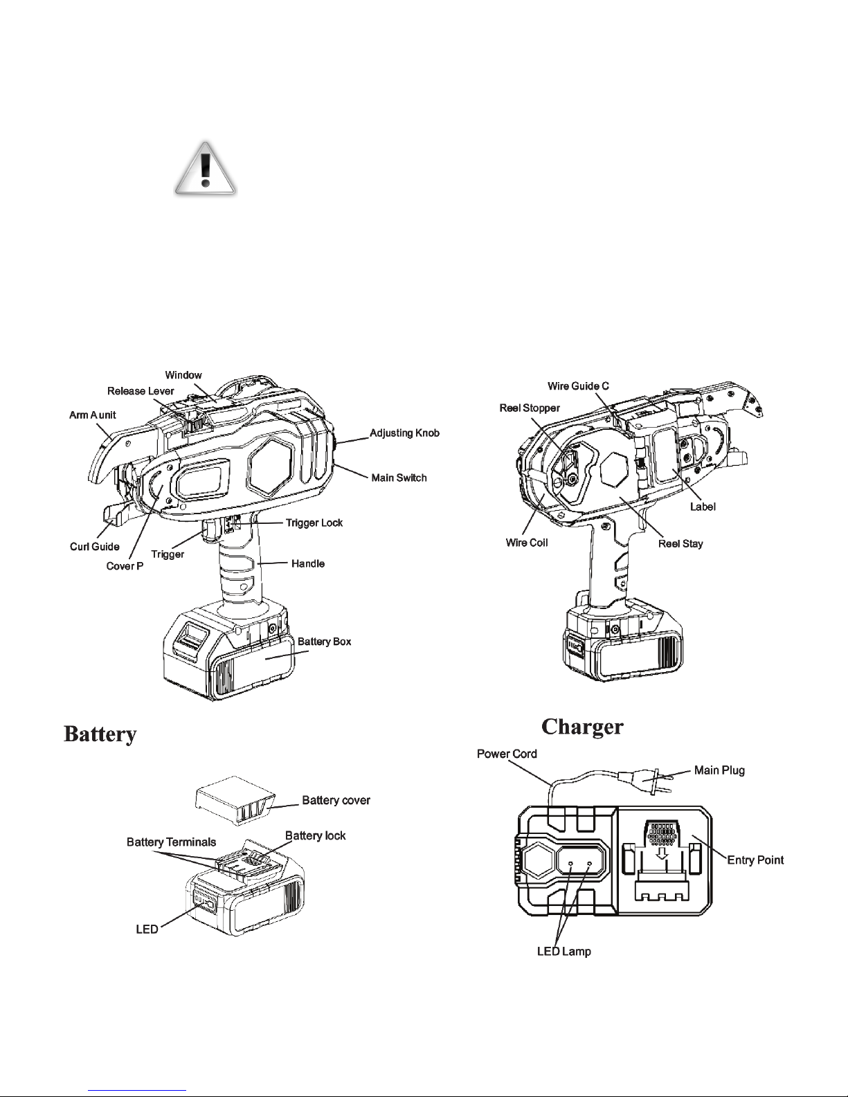
OPERATION INSTRUCTION
Machine Call-Outs
Please read this manual carefully before using
this machine to make sure you are familiar with
all safety and warning instructions.

Page | 3
Safety
This machine is a high-performance battery operated tool.
Failure to follow the warnings and instructions may result
in an electric shock, fire or serious injuries.
• Always operate the tool with personal protection
equipment (including eye protection, etc.). Using the
appropriate safety equipment at all times will avoid
body injury.
• Keep children and bystanders away while operating
this tool. Distractions may cause serious accidents.
• Do not aim the tool at those standing around your
work area. Serious accidents can happen if you mis-
handle this tool.
• Do not place your hand or position the machine near
your body. This could cause serious injury.
• Do not attempt to dismantle, modify or perform any
major maintenance on this tool. Modifications may
result in a deterioration of the tool’s performance and
may cause serious injury and void he warranty.
• Make sure that the main switch is in the off position
when the tool is not being used or when abnormalities
occur. When changing or adjusting the wire coil, or
when changing the battery pack, make sure to turn off
the main power switch and lock the trigger.
• Do not place fingers or hands in the wire coil area.
This may result in distortion of the coil and may cause
injury to you.
• Do not operate this tool in the rain or areas where
moisture is present. This may result in electrical
shock or accident.
• Stay particularly alert while working in a high area.
Do not operate any power tool under the influence of
drugs, alcohol, or medication. A moment of inatten-
tion may result in serious injury to you or someone
near you.
• Do not operate this tool in a hazardous area contain-
ing flammable liquid, gas or powders which may ignite
and cause a fire.
• The charger has been designed to use standard AC
power (100-240V ~ 50-60Hz). Do not recharge the
battery using a generator power supply as this will
cause the charger to malfunction.
• Our batteries charge best when the ambient tempera-
ture is between 32°F and 113°F. Super-cooling or over-
heating environments are not suitable for charging.
• Continuous use of the charger is not advised as this
will shorten the life span of the battery and the perfor-
mance of the charger itself. When not in the charging
mode the power supply must be turned off.
• Please do not carry the charger by the cord. Do not
pull out the power cord from the wall socket with the
cord, this will damage the cord and break the wires or
cause a short circuit. A damaged cord must be re-
paired or replaced immediately.
• Use only the specified charger that came with your
machine. Using an unauthorized charger may result
in damage to the battery components and possible
explosion.
• Avoid battery terminal contact with other metal ob-
jects. Trying to recharge the battery with an external
wire could result in a short circuit of the battery.
• Do not throw away the protective battery cap. Use it to
cover the terminal when not in use.
Safety Locks
Make sure that all safety features are
operational before using any power tool.
DO NOT OPERATE THE TOOL IF THE
SAFETY LOCKS ARE NOT FUNCTIONAL.
This tool is equipped with the
following safety devices:
The Main Switch: Please turn the main switch off when not
in operation.
The Trigger Lock: Always turn the trigger lock to the off
position when not in use or when changing the wire spool.
Technical Data
Tool Specs
Product No. BNT-25x BNT-40x BNT-58x
Weight Information
Tool Only 4.15 lbs.
(1.9 kg)
4.45 lbs.
(2.02 kg)
4.85 lbs.
(2.2 kg)
Tool + Battery 5.5 lbs.
(2.5 kg)
5.8 lbs.
(2.63 kg)
6.2 lbs.
(2.8 kg)
Tool+Battery
+Spool
6.4 ils.
(2.91 kg)
6.7 lbs.
(3.04 kg)
7.1 lbs.
(3.22 kg)
Height 11.81 in.
(300mm)
11.81 in.
(300mm)
12.2 in.
(310mm)
Width 4.29 in.
(109mm)
4.29 in.
(109mm)
4.29 in.
(109mm)
Length 11.06 in.
(281mm)
11.69 in.
(297mm)
12.28 in.
(312mm)
Ties per coil 160 - 220 120 - 160 90 - 120
Wraps per Tie 3 Wraps/tie
Time per Tie 0.6 - 0.8 sec per tie
Max Tying Diameter 1”
(25mm)
1.575”
(40mm)
2.283”
(58mm)
#3 x #4
bar
#6 x #6
bar
#8 x #8
bar
Battery Li-Ion 18V, 4.0Ah, 72Wh
(BNTLI-18)
Page | 4
Ties Per Charge 4000-5000 ties per charge
Additional Charger (BNTLI-18C)
Holster (BNH-40)
Extension Arm (BNEX-40)
Electronic Extension Arm (***)
Humidity 80% RH or less
Wire Technical Parameters
Part No. BNT-40-Wire
Diameter (in.) ø 0.03 (21 Gauge)
Material Q195 Galvanized
Length (in.) 3937 (approx)
Part No. BNT-40-Wire-USA
Diameter (in.) ø 0.03 (21 Gauge)
Material Q195 Galvanized
Length (in.) 3937 (approx)
Part No. BNT-40-Wire-P
Diameter (in.) ø 0.03 (21 Gauge)
Material Q195 Polycoated
Length (in.) 3937 (approx)
Battery and Charger Usage
Before inserting or removing the battery from this tool,
please set the main switch to the off position.
• To avoid a short circuit to the battery, always use the
battery terminal cover when it is not in use with the
tool.
• When placing the battery into the tool, press the bat-
tery lock before placing it into the battery holder. When
removing the battery, press the battery lock button
before pulling it out of the battery holder.
• Use 100-240V ~ 50-69Hz AC power supply for the
charger. Fully insert the battery into the charger slot
and it will begin to charge automatically as indicated
by the charging light. It will take approximately 74
minutes to fully complete the battery charge.
• It is recommended to charge the battery between 32°F
and 113°F. Do not charge in extreme cold or hot envi-
ronments.
Machine Operation and Methods
Before inserting and removing the wire spool turn the
main power switch to the off position, lock the trigger
switch and remove the battery.
When installing the wire coil spool.
only use recommended wire
without rust in this tool.
Only use recommended wire spools. Using non-standard
wire or spool could cause the tool to malfunction.
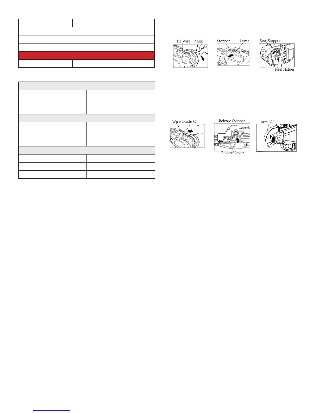
• Cut about 2 inches of wire from the coil.
• Push the reel stopper to release the reel stay and open
the gate at the same time.
• Install the wire pool with the left side facing the tool.
Lock the opening by closing the reel holder door.
• Insert the wire into the wire guide “C” (Note: the wire
must not be bent or curved).
• The wire must pass through the wire guide “C” in be-
tween the two feeding gears until it reaches the flared
tub. Then push the wire an additional 1/2” into the
flared tub.
• Keep pushing the wire until it reaches the arm “A” unit.
• Release the release stopper and confirm the release
lever has returned to its original position. (Note: the
wire must be clamped by the feeding gears).
• Remove the rest of the remaining adhesive tape from
the wire spool if any.
• Install the battery into the machine, when you hear
a locking sound the battery has been installed cor-
rectly. (Note: make sure that the main power switch is
in the off position and that the trigger is locked before
installing the battery).
• Turn on the main power switch. The machine is now
ready for use.
How to remove the wire coil spool
• Turn off the main power switch, lock the trigger and
remove the battery.
• Press the release lever and confirm that it is caught in
the open position.
• Remove the plastic wire spool.

Page | 5
The Tying Procedure
Unlock the trigger lock. Keep the mechanical arm on the
rebars to be tied with a 45° angle at a vertical position to
the rebars.
Press the trigger and the tool will tie automatically.
Remove the tool when the tying is complete.
Do not press the trigger when the mechanical arm is not
on the rebar surface. (Note: if this should happen turn off
the machine, position the trigger lock to the “off ” position
and remove the trapped wire with a pair of pliers inside
the machine mouth).
Adjust the tie tightness. There are 5 tightness levels that
can be adjusted with the “adjusting dial”.
Replacement of Gears
• Remove the screw that fastens the plastic housing
over the motor as show above.
• Remove the wire guide “C” which is fastened on the
plate as shown on previous page.
• Use a pair of pliers to remove the E-ring and washer
on the feed gear as shown above. Remove gear.
• With a pair of pliers remove Spring “A” at the end of
the release lever as shown above.
• Be careful not to drop the smaller Spring “B” at the
other end of the release lever when you take out
Spring “A” as shown above.
• Remove the hex screws of the release lever from the
plate and take out the release lever in the direction of
the arrow as shown above.
• After you remove the release lever you can remove the
E-rings with pliers and the feeding gear “B” and then
replace them.
After you finish replacing the gears all of the
tool parts must be reassembled in reverse order.
• First install the release lever and fasten it.
• Install spring “B” and the latch lever. Fit Spring “A” at
the end of the release lever
• Install the feeding gears, washer and E-ring in se-
quence
• Fix wire guide “C” on to the plate
• Finally attach the plastic cover with screws.
Care and Maintenance
• Perform a daily inspection prior to using this tool.
• Please maintain this electric tool carefully, making
sure that the adjustments are correct and that it has
been stored properly.
• Inspect the tool for damage and cracks in the housing
and that the power supply is in good working order.
• Make sure that the battery charger is the one that
came with your machine. Using another charger could
cause damage to the battery and/or charger and could
even cause a fire.
• Improper use of the battery could cause it to leak. If
this happens it will need to be replaced and properly
recycled. Do not touch any leaking material from this
battery. If you come in contact with the battery liquid,
flush with clean water and seek medical attention if
necessary.
• When not in use, store this tool carefully in the sup-
plied case. It can be washed with a soft cloth and
soapsuds after you finish work. Do not use petroleum
chemicals or alcohol to clean this tool.
• In the event that this tool malfunctions or drops in
performance you can call our Customer Service Repair
Center (800) 992-3833 or send us a note to mail@
bnproducts.com.

Page | 6
BNT-25X
mesh
#1 #2 #3 #4 #5
1/8” 1/4” 3/8” 1/2” 5/8”
6mm 8mm 10mm 13mm 16mm
mesh x x x x x x
#1 1/8” 6mm x x x x x x
#2 1/4” 8mm x x x x x
#3 3/8” 10mm x x x x x
#4 1/2” 13mm x x x x
#5 5/8” 16mm x x
BNT-40X
#1 #2 #3 #4 #5 #6 #7 #8 #9 #10
1/8” 1/4” 3/8” 1/2” 5/8” 3/4” 7/8” 1” 1-1/8” 1-1/4”
6mm 8mm 10mm 13mm 16mm 20mm 22mm 25mm 29mm 32mm
#1 1/8” 6mm x x x x x x x x
#2 1/4” 8mm x x x x x x x x x
#3 3/8” 10mm x x x x x x x x x
#4 1/2” 13mm x x x x x x x x
#5 5/8” 16mm x x x x x x x
#6 3/4” 20mm x x x x x x
#7 7/8” 22mm x x x x x
#8 1” 25mm x x x x
#9 1-1/8” 29mm x x x
#10 1-1/4” 32mm x x
#11 1-3/8” 36mm
#14 1-3/4” 43mm
#18 2-1/4” 57mm
BNT-58X
#3 #4 #5 #6 #7 #8 #9 #10 #11 #14 #18
3/8” 1/2” 5/8” 3/4” 7/8” 1” 1-1/8” 1-1/4” 1-3/8” 1-3/4” 2-1/4”
10mm 13mm 16mm 20mm 22mm 25mm 29mm 32mm 36mm 43mm 57mm
#1 1/8” 6mm x x x x x
#2 1/4” 8mm x x x x x x
#3 3/8” 10mm x x x x x x x
#4 1/2” 13mm x x x x x x x x
#5 5/8” 16mm x x x x x x x x
#6 3/4” 20mm x x x x x x x x
#7 7/8” 22mm x x x x x x x
#8 1” 25mm x x x x x x
#9 1-1/8” 29mm x x x x x
#10 1-1/4” 32mm x x x x
#11 1-3/8” 36mm x x x
#14 1-3/4” 43mm x x
#18 2-1/4” 57mm x
Product Specifications and Technical Parameters

Page | 7
Common Faults Warning
Sound
Indicator
Light Items To Inspect Possible Cause Actions
The machine does
not work after
putting in a new wire
spool.
None Off Inspect the battery
terminal
Oxidation or there
is dirt on the elec-
trodes
Use a dry cloth to
wipe the surfaces
Beep---- On Confirm that the bat-
tery is charged
Low power in the
battery
Recharge the bat-
tery
Beep,
Beep,Beep
On Off On
Off On off...
Check wire guide “A”
to see if there is stray
wire in the guide
The head of the
wire was caught
in the guide
Using a pair of pli-
ers remove the wire
Beep, Beep,
Beep, Beep...
On Off On
Off On off...
Check the curl guide to
see if there is a stray
wire caught in the tool
Tying strength
may be too strong
Adjust the tying
force and remove
the caught wire
The wire does not
feed correctly
Beep, Beep On Off On
Off On off...
Check the curl guide The curl guide is
open
Close the curl guide
Beep, Beep,
Beep
On Off On
Off On off...
Check the diameter of
the rebars
The diameter of
the rebar exceeds
chart
Use the proper di-
ameter rebars
Beep, Beep,
Beep, Beep...
On Off On
Off On off...
Check the tightness of
the wire coil
The wire is too
tight on the coil
Clear the wire
Irregular binding and
wire stepping out of
the curl guide
None On- Alarm when pressing
the trigger-- No alarm
when released
Overheated motor
from constant use
Let the motor cool
down
Failure to cut the
wire after binding
None On- Check if the wire hits
the rebar when tying
The wire hitting
the rebar will stop
the action
Pay attention so
that the wire does
not hit the rebar
Tying knot is loose
None On- Check to see if the
cutting mechanism is
working correctly
There may be
a stray piece of
wire in the cutting
mechanism
Clean the cutting
mechanism
None On- Check the operation
instruction
Wrong operation Please read the
operation manual
Tying knot is not
correct
None On- Check the tying
strength
The tying force is
too great
Adjust to the proper
tying force
Common Faults
This tool alerts you to the following fault conditions by means of a warning sound and warning light. If the
problem is not solved please contact our maintenance support department: (800) 992-3833.

Page | 8

Page | 9
PARTS LIST BNT-40X
Part Description Qty.
101 Arm A 1
103 Connecting Plate 1 1
104 Fixed Cutter 1
105 Torsion Spring 1 1
106 Cutter 1
107 Cutter Lever A 1
108 Connecting Rod 1 1
109 Cutter Sleeve 1
110 Arm A unit 1
111 Shaft Screw 1
112 Washer 4 1
113 Cutter Lever C 1
114 Arm A Unit Assy 1
115 Wire Guide A 1
201 Stopper Shaft 1
202 Torsion Spring 3 1
203 Curl Guide 1
204 Curl Guide Assy 1
301 Hook 2
302 Key A 1
303 Sleeve A 1
304 Sleeve Guide 1
305 Cutting Ring Guide 1
306 Cutting Plate 1
307 Cutting Ring Washer 1
308 Tip Axis Guide Assy 1 12.4g
309 Tip Axis B 1
310 Key B 2
311 Tip Axis A 1
312 Pin 1 2
313 Comp. Spring 2 1
314 Bumper 1
315 Internal Gear 1
316 Pin 5 1
317 Planet Gauge Unit 1
318 Planet Gear 4
319 Gear Press Wheel 1
320 Twisting Motor Gearbox 1
321 Sun Gear Unit 1
322 Motor Fixing plate 1
323 Twisting Motor Unit 1
256.5g
324 Comp. Spring 1 1
PARTS LIST BNT-40X
Part Description Qty.
325 Route PWB Unit 1 1g
326 Magnetic Plate 1
327 Twister Assy 1
191.6g
328 Twisting Motor Assy 1
326.8g
401 Feeding Gear B1 1
402 Partition Plate 1
403 Feeding Gear Shaft 1
404 Dust-Proof strip 1
405 Feeding Motor Gearbox 1
406 Feeding Motor Unit 1
157.4g
408 Hollow Pin 1 1
409 Release Lever 1
410 Comp. Spring 3 1
411 Step Pin 1 1
412 Feeding Gear B2 1
413 Wire Guide C 1
414 Rubber Base 1
415 Pipe 1
416 Feeding Motor Assy 1
206.8g
417 Release Lever Assy 1
501 Reel Press D 1
502 Torsion Spring 7 1
503 Reel Press A 1
505 Reel Press Centre Axis 1
506 Torsion Spring 7 1
507 BN Reel Press limit Axis 1
601 Step Pin 2 1
602 Release Stopper 1
603 Reel Stopper 1
605 Comp. Spring 4 2
606 Window 1
607 Joint Reel Magazine 1
608 Reel Guide 1
609 Fixing Plate 1 1
610 Hollow Pin 7 11
611 Motor Cover 1
612 Step Pin 3 2
613 Torsion Spring 5 1
614 Rubber Washer 2
615 Reel Stopper 1
616 Torsion Spring 6 1

Page | 10
PARTS LIST BNT-40X
Part Description Qty.
617 Reel Stay 1
618 Strength Plate 1
619 Nut M3 15
620 Adjusting PWB Unit 1 3.8g
621 Adjusting Spring 1
622 Joint Knob 1
623 LED Unit 1
624 Adjusting Plate 1
626 Adjusting Knob 1
627 Main Switch Unit 1 3.8g
630 Fixing Plate 2 1
631 Jaw Pin 1
632 Brake Motor Platen 1
633 Jaw 1
634 Socket Cap 1
635 Socket 1 0.8g
636 Feeding PWB unit 1 2.4g
637 Sensor PWB D Unit 1 1g
638 Trigger Switch 1 3g
639 Trigger Switch 1
640 Comp. Spring 5 1
641 Trigger Lock 1
642 Bolt 1
643 Torsion Spring 4 1
644 Switch Lever 1
645 Pin 4 1
647 Cover L Unit 1
648 Frame L 1
649 Frame R 1
650 Cover P Unit 1
651 Belt Hook 1
652 Electrode Unit 1 23.4g
653 18V Li-ion Battery 1
583.6g
654 Battery Connecting Wire 1 5.2g
655 Main PWB Unit 1 93.5g
656 Feeding Motor Connecting Wire 1 2g
657 Sensor Connecting Wire 2 0.5g
658 Adjusting Connecting Wire 1 1.5g
659 Reel Stopper Assy 1
660 Motor Cover Assy 1
661 Reel Stay Assy 1
PARTS LIST BNT-40X
Part Description Qty.
662 Main Switch Base Assy 1 26.8g
663 Frame R Assy 1
664 Frame L Assy 1
665 Feeding-Response PWB unit 1
666 BN Cam Connecting Wire 1
901 Hex Bolt M4X6 2
904 Hex Bolt M3X4 2
905 Hex Bolt M3×5 1
906 Hex Bolt M3×6 5
908 Hex Bolt M3×8 5
910 Hex Bolt M3×10 6
912 Hex Bolt M3×12 5
914 Hex Bolt M3×14 8
916 Hex Bolt M3×16 5
922 Hex Bolt M3×22 1
930 Spring Washer φ3 4
931 Spring Washer φ4 1
932 Washer 4
933 Washer 2 1
934 Washer 3 1
935 Nut M3 (T4) 1
950 Button Head Screw M3X6 3
951 Button Head Screw M3X8 8
952 Button Head Screw M4X20 1
960 E-ring 3 3
961 E-ring 4 2
962 E-ring 5 1
963 E-Ring 2 1
964 C-ring 20 1
970 Spring Pin φ2.5 2
980 Hex Screw M3×4 5
981 Pan-head Screw ST2.2×6 5
982 Pan-head Screw ST3×8 2
983 Countersunk screw M2×4 1
984 Countersunk Scew M3×10 1
985 Pan-head Countersunk screw
M2×4
1
990 Bearing 1 1
991 Bearing 2 1
992 Bearing 3 1
993 Bearing 4 1

Page | 11
The BNT-Series are hand-held battery operated tools. In this
manual you will learn that these machines consists of four parts:
the machine body, special wire coil, battery box and a charger.
The tool is designed to be used for the fast tying of rebar or steel
used in construction sites for the building trades. Due to its
speed, convenience and safety, this machine can save a great deal
of valuable labor and material resources. In addition, the parts
and components as well as advanced production technologies
are made from well-known manufacturers both here and abroad.
This machine was developed as an economical and practical tying
machine with many international patents.
BN Products-USA
3450 Sabin Brown Road
Wickenburg, AZ 85390

Page | 12
This manual suits for next models
2
Table of contents
Other BN Products Power Tools manuals


Popular Power Tools manuals by other brands


Makita
Makita 6924N instruction manual

Black & Decker
Black & Decker JS660 instruction manual

ISC
ISC RP280 Instructions for Installation/Set-up, Operation, and Maintenance

Westfalia
Westfalia JIM-KZ4-100 instruction manual

Sherline Products
Sherline Products 8-DIRECTION MILL Supplement manual

Far Tools
Far Tools SN 30 manual