Bistos BT-250 User manual
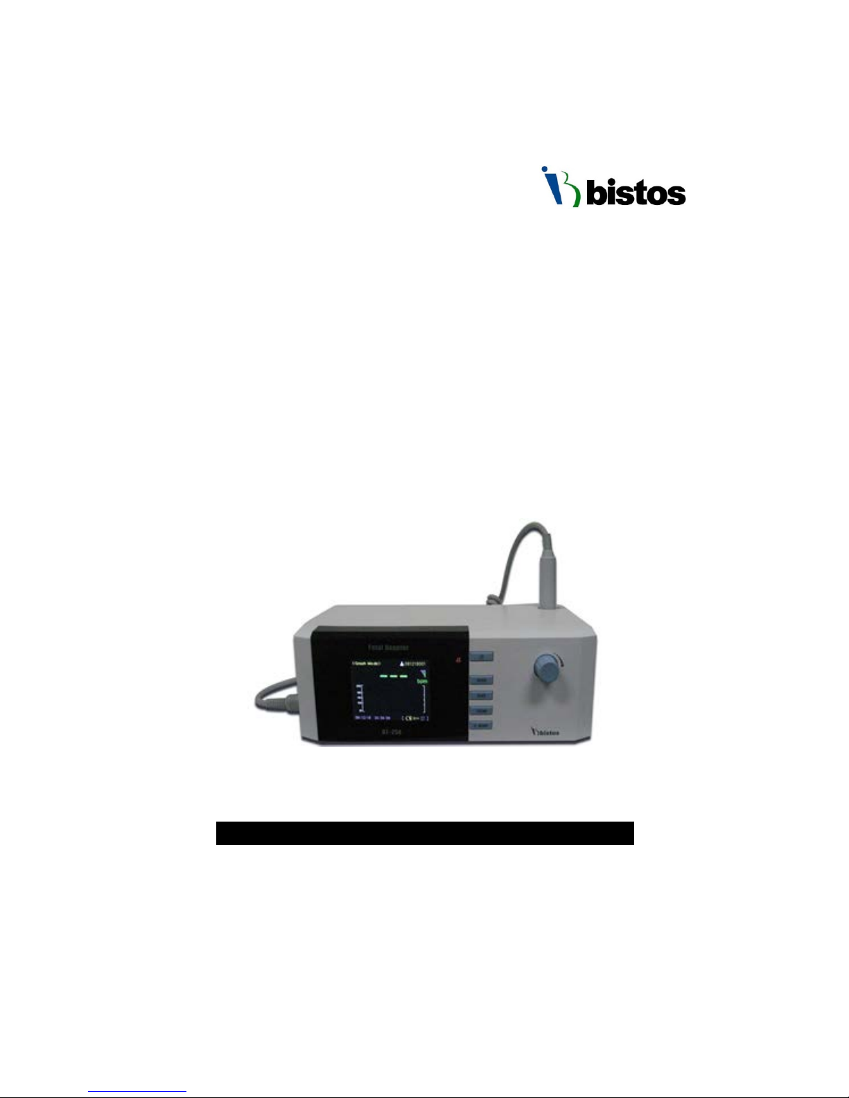
BT-250
Ultrasound Doppler System
Operation Manual
BT-250
Keep this manual for future reference
P/N: 250-ENG-OPM-EUR-R06

BT-250 Operation Manual
1
P/N: 250-ENG-OPM-EUR-R06
Bistos Co., Ltd.
2018,03
Proprietary Material
Information and descriptions contained in this manual are the property of
Bistos Co., Ltd. and may not be copied, reproduced, disseminated, or
distributed without express written permission from Bistos Co., Ltd.
Information furnished by Bistos Co., Ltd is believed to be accurate and
reliable. However, no responsibility is assumed by Bistos for its use, or any
infringements of patents or other rights of third parties that may result from
its use. No license is granted by implication or otherwise under any patent
or patent rights of Bistos Co., Ltd.
The information contained herein is subjects to change without notice.
Prepared by:
Bistos Co., LTD.
7th FL., A Bldg., Woolim Lions Valley 5-cha, 302,
Galmachi-ro, Jungwon-gu, Seongnam-si, Gyeonggi-do, Korea
Telephone: +82 31 750 0340
Fax: +82 31 750 0344
Revision 06
Printed in Korea
Copyright © Bistos Corporation 2017. All rights reserved.

BT-250 Operation Manual
2
P/N: 250-ENG-OPM-EUR-R06
Bistos Co., Ltd.
2018,03
Table of Contents
1.·System basics·············································································3
1.1 Device description and Intended Use····························································3
1.2 Options and Accessories················································································3
1.3 Description of Front Panel ···········································································4
1.4 Description of Side Panel ·············································································4
1.5 Description of Rear Panel ············································································5
2.·Preparing to use ·······································································6
2.1 Place to use·····································································································6
2.2 AC/DC adapter and Transducer connection ·················································6
2.3 Factory Default Setting ·················································································7
2.4 Understanding the BT-250 Display Screen ····················································7
2.5 Button description ························································································9
2.6 BT-250 Control Knob ····················································································· 10
2.7 Data Saving ··································································································· 11
2.8 Trend Mode (Data Tracing Mode) ································································11
3.·Monitoring fetal heart rate ························································13
4.·Cleaning and disinfection ·························································15
4.1 Monitor ·········································································································15
4.2 Transducer ····································································································15
5.·Trouble shooting and maintenance ··········································17
5.1 Transducer ····································································································17
5.2 Battery Disposal and Handling ······································································17
5.3 Maintenance ·································································································17
6.·Safety and regulatory information ············································18
6.1 Warnings ·······································································································18
6.2 Cautions ········································································································20
6.3 General precaution on environment ····························································22
6.4 Symbols ·········································································································23
6.5 Compliance to the standards ········································································ 24
6.6 Guidance and manufacturer’s declaration – Electromagnetic emissions·······25
6.7 Guidance and manufacturer’s declaration – electromagnetic immunity ·····25
6.8 Recommended separation distances between portable and mobile RF
communications equipment and the BT-250 ················································28
7.·Specifications·············································································29
Product Guarantee ·······································································30
BT-250 Operation Manual
3
P/N: 250-ENG-OPM-EUR-R06
Bistos Co., Ltd.
2018,03
1.1 Device description & Intended Use
The BT-250 is a desktop fetal Doppler that measures the fetal heart rate, which
is displayed on a LCD display, and outputs the fetal heart sound through built-in
speaker. This device is for use only by trained medical personnel.
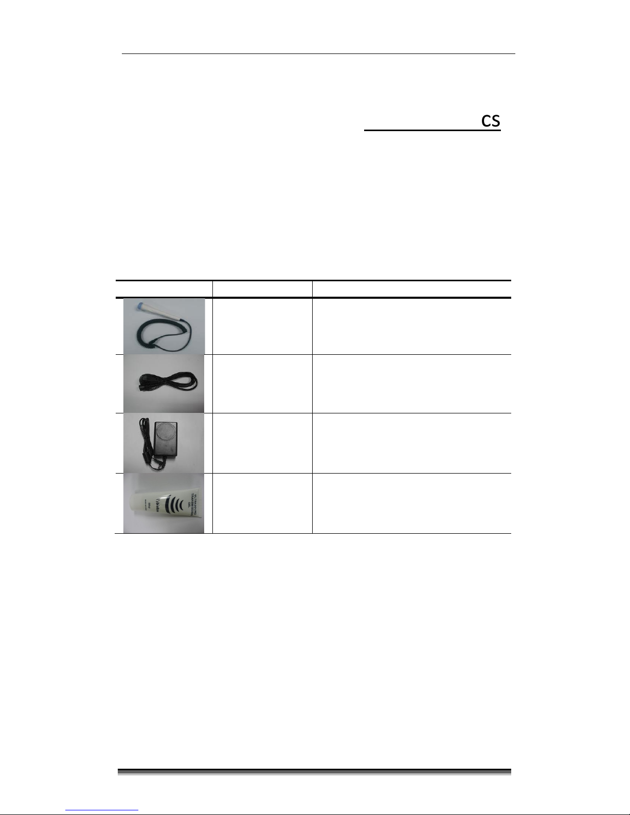
1.2 Options and Accessories
Accessory
Name
Description
Doppler
transducer
(1ea)
Ultrasound transducer for measuring
FHR
IPX7 : Waterproof
(1 meter of water for up to 30 minutes.)
Power cord
(1ea) AC power cord
Power adaptor
(1ea)
AC/DC power adaptor
Input : AC100~240 V[50/60 Hz]
Output : DC 9V, 2.0A
Ultrasound gel
(1ea) Ultrasound transmission gel
Table 1.1. BT-250 Accessories
1
System basics
BT-250 Operation Manual
4
P/N: 250-ENG-OPM-EUR-R06
Bistos Co., Ltd.
2018,03
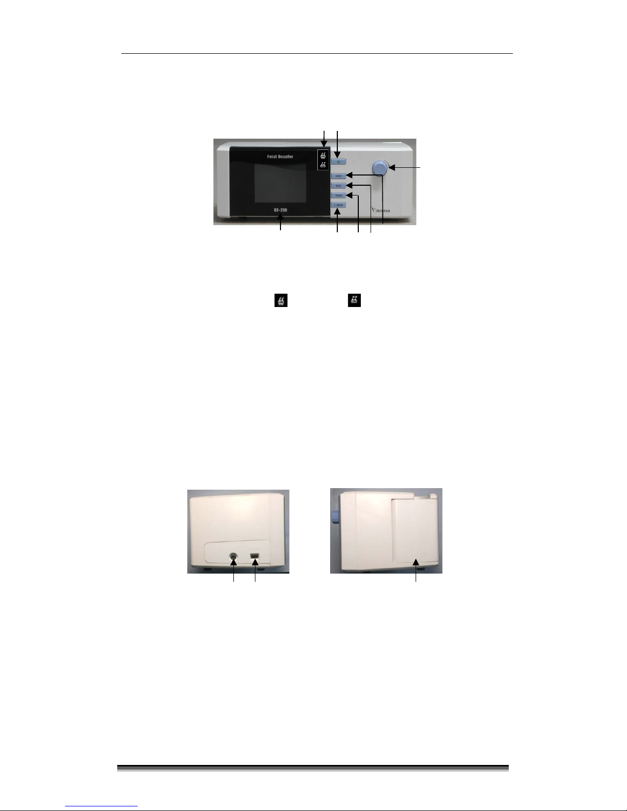
1.3 Description of the Front Panel
Fig. 1.1 BT-250 Front Panel
①Power Indicating LED ( AC: Green / Battery: Orange)
②Power On/Off Button
③Control knob
④Mode change button
⑤Save On/Off button
⑥Trend mode Button
⑦Event mark
⑧TFT-Color LCD
1.4 Description of the Side Panel
Fig. 1.2 Left Panel Fig. 1.3 Right Panel
①Earphone jack connector
②Doppler transducer connector
③Doppler transducer holder
①
②
①
⑧
④
③
⑤
⑥
⑦
③
②
BT-250 Operation Manual
5
P/N: 250-ENG-OPM-EUR-R06
Bistos Co., Ltd.
2018,03
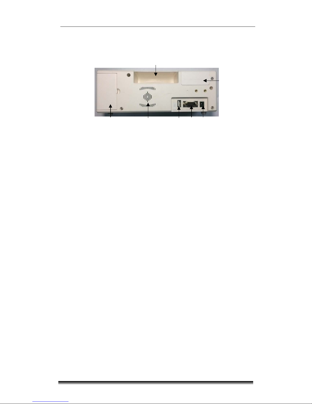
1.5 Description of the Rear Panel
Fig. 1.4 Rear Panel
①Grip
②Battery cover
③AC/DC adaptor connector
④RS-232C port
⑤USB port
⑥Built-in speaker
⑦Doppler transducer holder
①
②
③
④
⑥
⑦
⑤

BT-250 Operation Manual
6
P/N: 250-ENG-OPM-EUR-R06
Bistos Co., Ltd.
2018,03
2.1 Place to use
Certain strong electromagnetic fields can interfere with the ultrasound
transducer and cause a false heart rate reading. This interference is rare, and
usually found in the vicinity of large machinery. In order to avoid the possibility
of these interfering signals being analyzed as fetal heart rates, the following
procedure should be followed whenever the monitor is to be used in a new
location, or if it is known that electrical machinery is being operated in the
vicinity.
After connecting the ultrasound Doppler transducer, turn on the monitor and
observe the heart rate indications on the screen for 30 seconds while no signal
input applied to the transducer surface. Intermittent display of random heart
rates is acceptable. However, if there is a constant display of a heart rate lasting
more than 5 seconds, this is an indication that there is a source of
electromagnetic interference in the vicinity. The following steps should be
taken to determine if it is possible to use the monitor in this environment.
Move all line cords and line-powered equipment at least 6 feet (1.8 meter)
away from the BT-250. Check for extension cords running behind or under
the bed and equipment in adjacent rooms. If the artifact heart rate
indication ceases, the monitor may be used normally.
Remove the line cord from the monitor’s power supply. If the artifact heart
rate indication ceases, the monitor may be used normally.
If these measures do not result in cessation of the artifact heart rate, the
monitor cannot be safely used in this environment.
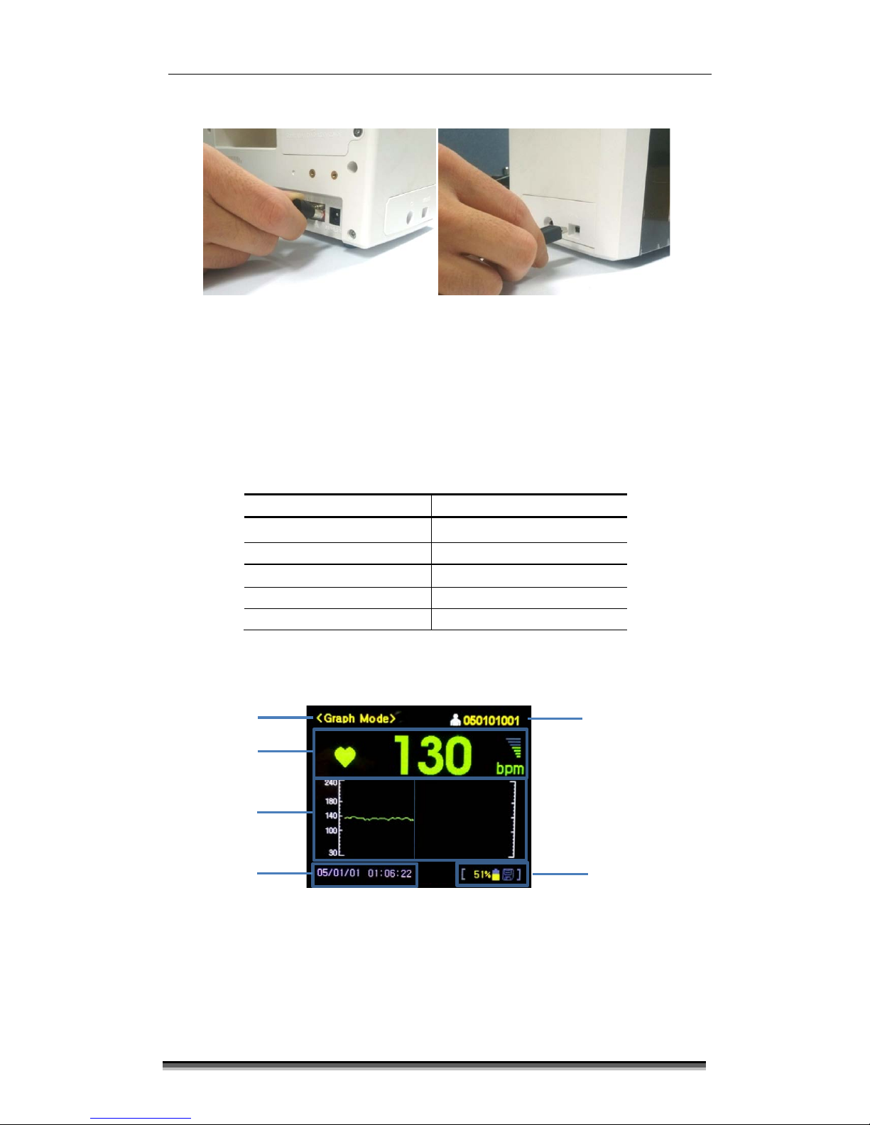
2.2 AC/DC adaptor & Transducer Connection
Connect the power cord which supplied by Bistos Co., Ltd. to power outlet and
power adapter receptacle. Connect the adapter plug to the BT-250 AC/DC
adaptor connector as shown in Figure 2.1. Turn on the BT-250 by pressing down
the power ON/OFF button about 2 seconds.
Connect the Doppler transducer cable to BT-250 as shown in the figure below.
2
Preparing to use
BT-250 Operation Manual
7
P/N: 250-ENG-OPM-EUR-R06
Bistos Co., Ltd.
2018,03
Fig. 2.1 Power adaptor and Transducer Connection
2.3 Factory Default Setting
To enter the factory setting mode, turn on BT-250 by press down the power ON/OFF
button for about 2 seconds while press down the control knob simultaneously. In
factory setting mode, all configuration parameters are initialized to factory setting
value. The initial factory setting values of each parameter are as below;
Setting parameter
Factory default value
Monitoring Mode Number Mode
Graph Area
30~240
Auto Shunt Down
5
Language
English
Start Volume
3
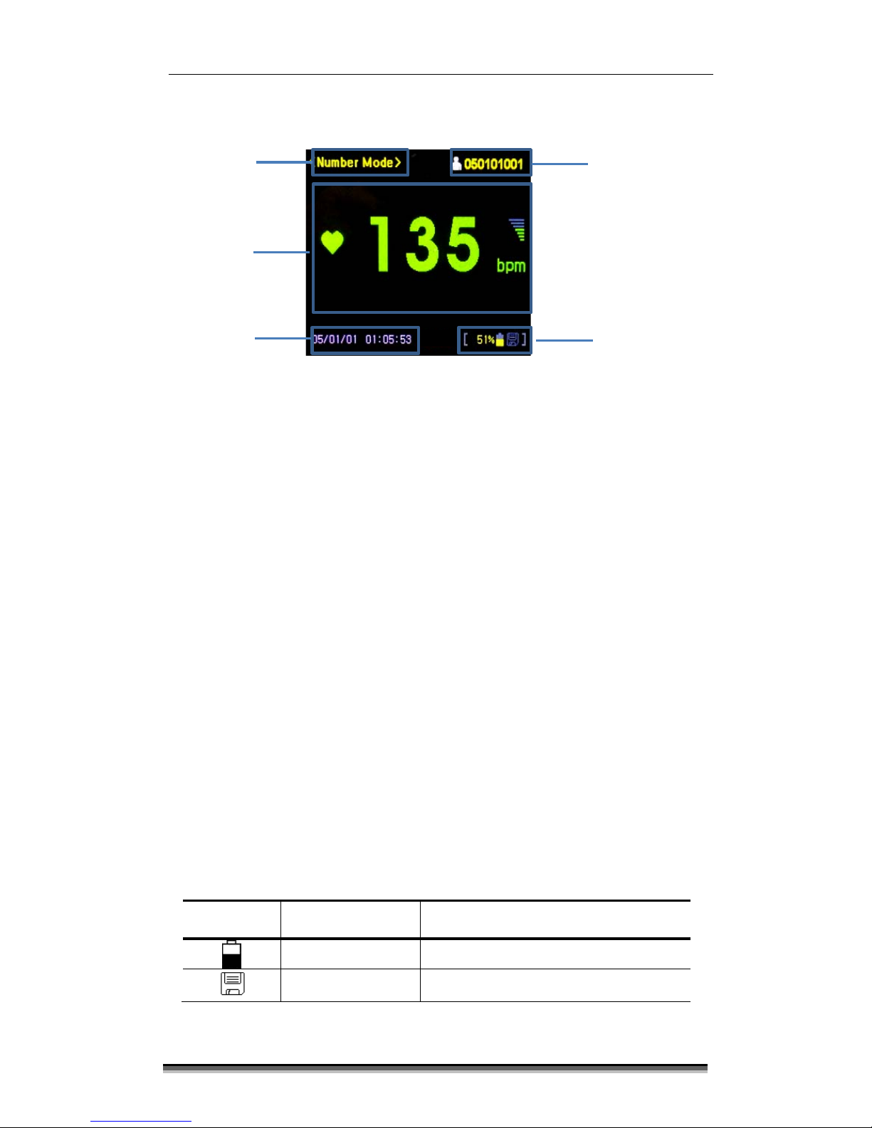
2.4 Understanding the BT-250 Display Screen
Fig. 2.2 Main Monitoring Screen – Graph Mode
Status frame
FHR graph
frame
Patient ID frame
Mode frame
FHR frame
Date/Time
frame
BT-250 Operation Manual
8
P/N: 250-ENG-OPM-EUR-R06
Bistos Co., Ltd.
2018,03
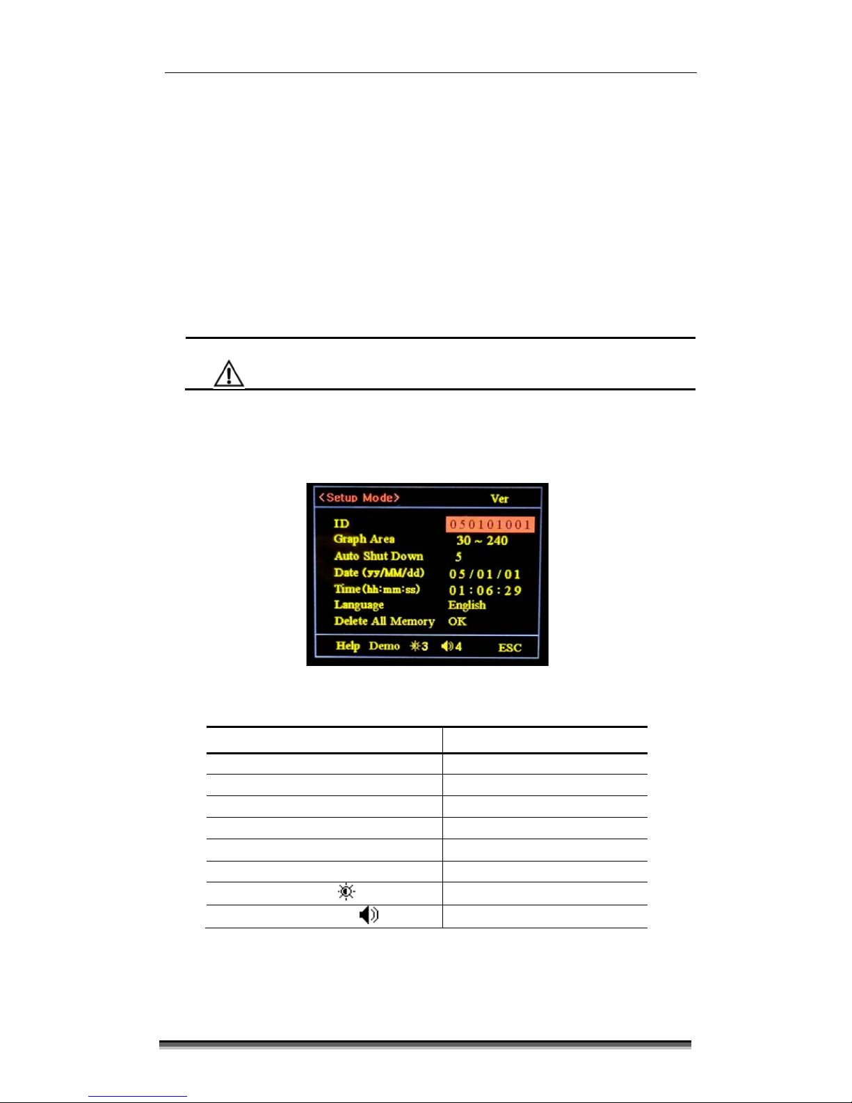
Fig. 2.3 Main Monitoring Screen – Number Mode
To change the monitoring mode between “Number Mode” and “Graph Mode”, press
the [MODE] button.
2.4.1 Mode frame
The mode frame shows the current mode. There are monitoring mode
(Number and Graph), setup mode and trend mode.
2.4.2 Heart Rate frame (FHR frame)
The heart rate (FHR) frame displays the fetal heart rate with a heart icon and
current speaker volume setting. The heart icon blinks at the measured heart
rate interval. The solid heart icon blinks when a valid rate is present and only
the outline of heart icon blinks when a measured rate is unstable or weak.
The volume icon indicates the current speaker volume setting for the fetal
echo sounds.
2.4.3 Heart Rate Graph frame (FHR Graph frame)
The Heart Rate (FHR) Graph frame displays a graphical representation of the
fetal heart rate. The vertical scale is labeled corresponding to the recorder
paper (30 to 240 BMP).
2.4.4 Status frame
This frame shows battery status and data saving status.
Symbol Name Description
Battery Status Icon Indicates the battery residual quantity
Save Icon Indicates the data saving status
Mode frame
FHR frame
Date/Time
frame
Patient ID frame
Status frame

BT-250 Operation Manual
9
P/N: 250-ENG-OPM-EUR-R06
Bistos Co., Ltd.
2018,03
When alarm occurs, alarm status is shown below.
Symbol Name Description
Low Battery Alarm
Icon
Blinking until AC/DC adapter is
connected.
2.4.5 Patient ID frame
This flame displays the patient identification number. The BT-250 uses time and
date information to generate the part of ID number (6 digits). The last 3 digits
used for the individual patient ID. Default ID number is YYMMDD001 when
YYMMDD is the current date information. To change the individual ID number
(3 digits) enter [Setup mode] by pressing control knob button. (Refer to ‘4.4 BT-
250 Control Knob’ section)
2.4.6 Time and Date
This frame shows the current time and date saved. These settings can be
changed as needed. (Refer to ‘4.4 BT-250 Control Knob’ section)
2.5 Button description
There are 5 buttons located on the front panel. The operation of the buttons is
summarized below.
CAUTION
Never use sharp or pointed objects to operate the front-
panel buttons
Symbol Description
Turns power on or off.
MODE Display mode Change [ Graph Mode ↔Number Mode]
SAVE Start and stop the save function.
TREND
To enter into or exit from Trend mode. The trend frames
shows historical patient data and the control knob
provides navigation capability.
E.MARK Marking event
BT-250 Operation Manual
10
P/N: 250-ENG-OPM-EUR-R06
Bistos Co., Ltd.
2018,03
2.6 BT-250 Control Knob
In monitoring mode, the control knob decrease and increase the fetal heart
audio volume.
In Trend mode, use Control Knob to search the stored data to recall. After
selecting the stored data, press down the Knob to see the data.
In the Setup mode, use Control Knob to adjust parameters. Press down the
control knob in monitoring mode to enter Setup mode. Rotate the knob to
select the item and press down the knob for editing. Rotate the knob again to
change the value and press knob after change.
CAUTION
Pressing the knob on ‘Delete All Memory’ item makes the all
saved data is deleted.
To save the changed value and exit from Setup mode, select ‘ESC’ and press the
knob. The BT-250 will return to monitoring mode after storing the changes
values.
Fig. 4.3 System setup menu
Configuration parameter Available List
ID (Last 3 digits)
001 ~ 999
Graph Area
30~240/100~180
Auto Shut Down (minutes)
5/10/15/30/off
Date YY/MM/DD
Time
HH:MM:SS
Language
English/Spanish
Bright
1~5
Start Volume
1~7

BT-250 Operation Manual
11
P/N: 250-ENG-OPM-EUR-R06
Bistos Co., Ltd.
2018,03
2.7 Data Saving
BT-250 has a data saving function. It can save up to 4 hours (10 minutes for one time,
total 25 times).
Press [SAVE] button to start saving. When the function is stared, the save icon [ ]
is activated and rotated.
Press [SAVE]button again to stop saving.
2.8 Trend Mode (Data Tracing Mode)
Press [TREND] button to enter the Trend mode. In trend mode, the saved data is
displayed.
Fig. 4.4 Trend Mode display
Rotate the control knob to select the saved data and press it to see the saved data.
Fig. 4.5 Saved Data Tracing Mode display
Mode frame
FHR frame
Saved data
Start Time
frame
Data Searching
Frame
FHR graph
frame
Patient ID frame

BT-250 Operation Manual
12
P/N: 250-ENG-OPM-EUR-R06
Bistos Co., Ltd.
2018,03
2.8.1 Saved Data Start Time Frame
This frame shows the date and start time of data saving.
2.8.2 Patient ID Frame
This frame shows the saved patient ID.
2.8.3 Data Searching Frame
This frame is consisted of control buttons for searching saved data. The description of
each button is shown below:
Button
Description
Searching for saved data in previous page.
Searching for saved data in next page.
Tracing the saved data

BT-250 Operation Manual
13
P/N: 250-ENG-OPM-EUR-R06
Bistos Co., Ltd.
2018,03
Fetal heart rate is measured by placing an ultrasound Doppler transducer on
the maternal abdomen and by analyzing the echo signal to calculate a heart
rate and an audible sound.
Step 1: Preparing the Monitor
Turn the monitor on and verify that the normal monitoring screen appears on
the display. Do not use the BT-250 if an error occurs.
Check whether the monitor is powered from the internal battery or AC power.
If operating on the internal battery, check the power status frame on the
display to determine whether the battery has sufficient charge to complete the
monitoring session. Use the AC power if the battery is too low.
Step 2: Acquiring the Fetal Heart Signal
Determine the location of the fetal heart using palpation or a fetoscope. Place
the transducer on the maternal abdomen and listen for the fetal heart signal.
Reposition the transducer for the loudest fetal heart signal and verify the heart
icon on the screen is blinking at the fetal heart rate.
Secure the ultrasound transducer. Make sure the transducer is still positioned
for the loudest fetal heart signal.
Verify the monitor is displaying fetal heart rate values and that the heart icon
on the screen is blinking at the measured heart rate.
Step 3: Monitor Adjustments
Readjust the volume settings for the desired loudness.
3
Monitoring fetal heart rate
BT-250 Operation Manual
14
P/N: 250-ENG-OPM-EUR-R06
Bistos Co., Ltd.
2018,03
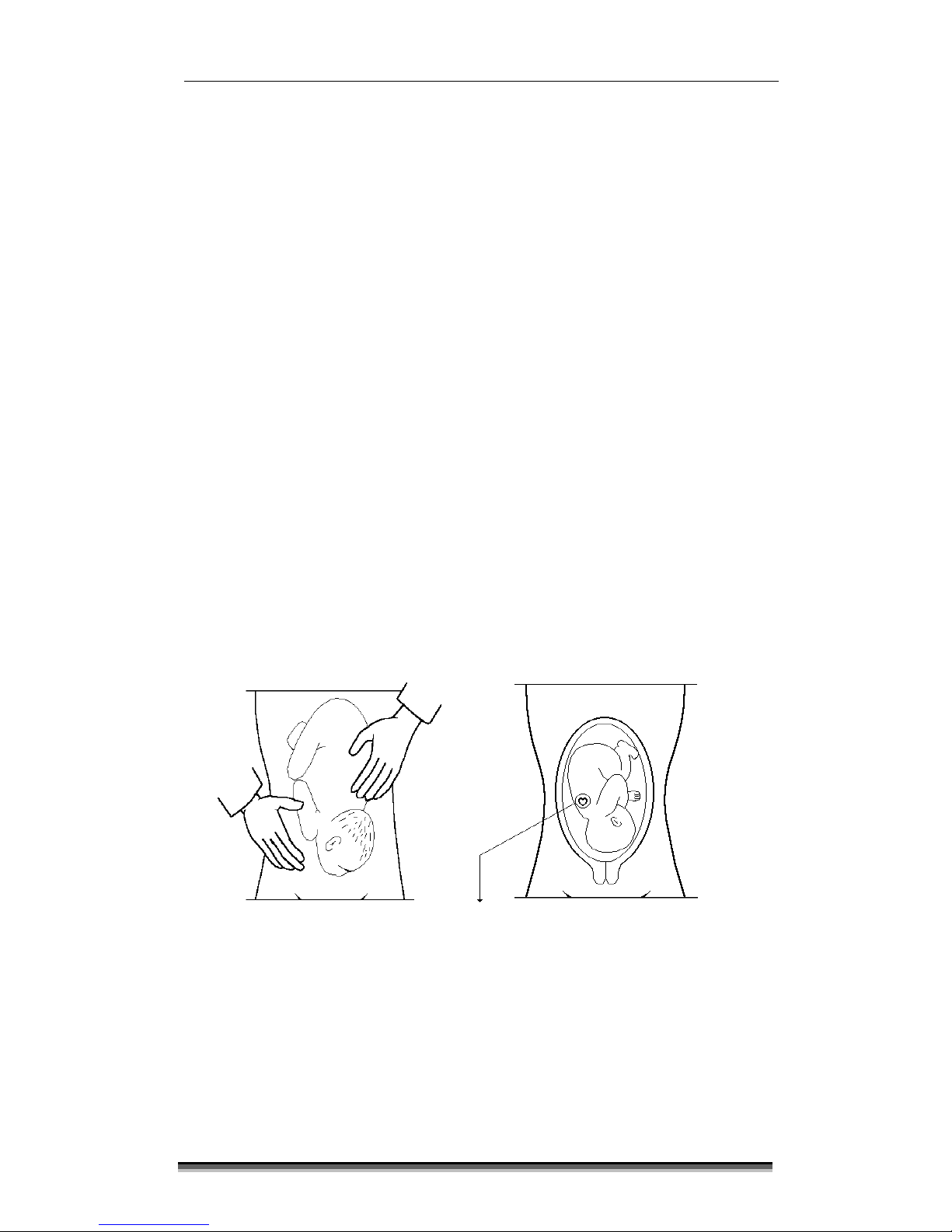
Detail Procedure
①Explain procedure to the patient.
②Turn the monitor power on. The power button is located on the front panel.
③Determine the position of the fetus using Leopold’s maneuvers. The
strongest fetal heart tones are heard through the fetal back.
④Plug the ultrasound transducer cable into the connector labeled “DOP.”
⑤Apply a small amount of ultrasonic transmission gel to the face of the
transducer.
⑥Place the transducer face down on the maternal abdomen over the area
determined to be the fetal back.
⑦Volume Up/Down may be used to adjust the volume.
⑧Reposition the transducer as necessary until the clearest heart sound is
heard. Three to five seconds after a clear heart beat sound is heard, the
heart icon will flash synchronously with the sound. This indicates that the
received signal is stable.
[Figure 3.1 Direction of Doppler Transducer]
Ultrasound transducer

BT-250 Operation Manual
15
P/N: 250-ENG-OPM-EUR-R06
Bistos Co., Ltd.
2018,03
The BT-250 requires proper care and preventive maintenance. This ensures
consistent operation and maintains the high level of performance necessary in
monitoring procedures.
All exterior parts and transducer should be cleaned and/or disinfected as
necessary or between uses. Clean each compartment to remove any surface
particles.
4.1 Monitor
Turn off the monitor prior to clean.
Use a clean gauze pad or lint-free cloth, lightly moistened with a mild
detergent, to wipe the surface of monitor. Ensure that cleaning solution does
not seep into the monitor. Be careful not to power on the monitor during
cleaning.
After cleaning, use a clean, lint-free cloth to dry the surface.
WARNING
Unplug the monitor from the AC power source and detach
all accessories before cleaning. Do not immerse the unit in
the water or allow liquids to enter the case.
CAUTION
Take extra care when cleaning display surface, which are
sensitive to rough handling. Rub the lens that covers them
with a soft, dry cloth.
4.2 Transducers
WARNING
To avoid electrical shock and damage to the monitor,
disconnect the transducer prior to cleaning and disinfecting.
CAUTION
Transducers are sensitive instruments – irreparable damage
may occur if they are dropped, knocked against other
objects, cut, or punctured. Do not attempt to repair to alter
any part of a transducer.
Do not autoclave or EO gas sterilize.
4Cleaning and disinfection

BT-250 Operation Manual
16
P/N: 250-ENG-OPM-EUR-R06
Bistos Co., Ltd.
2018,03
To clean a transducer,
1. Disconnect the transducer from monitor.
2. Moisten a clean gauze pad with water and wipe the transducer to
remove any gel or particles remaining on the transducer. If water is not
effective, then you can use an approved pre-cleaner or low-level
disinfectant.
3. Carefully wipe the entire transducer, including the cable and connector.
4. After cleaning, use a clean cloth to dry the transducer.
To disinfect a transducer,
1. Disconnect the transducer from the monitor.
2. Thoroughly clean, rinse, and dry the transducer.
3. Take care to keep the cable strain relief and the connector of the
transducer dry while immersing the transducer in an approved
disinfectant.
4. Carefully follow the disinfectant manufacturer’s instructions for
disinfections or high-level disinfection.
5. After disinfecting or high-level disinfecting, use a clean cloth to dry the
transducer.
The following high-level disinfectant agents have been approved for use with
transducers.
Cidex OPA
Cidex Plus

BT-250 Operation Manual
17
P/N: 250-ENG-OPM-EUR-R06
Bistos Co., Ltd.
2018,03
5.1 Transducer
To test an ultrasound transducer:
1. Properly connect the transducer to the side of the monitor.
2. Turn on the monitor.
3. Adjust the speaker volume to an audible level.
4. Hold the transducer on one hand and tap on the transducer face with the
other hand. The tapping sound should be heard from the monitor
speaker if the transducer operating properly. The transducer is
operating properly if you can hear noise from the speaker. Do not use the
transducer if no sound is heard or until the proper cause is identified and
repaired.
5.2 Battery Disposal and Handling
Be sure to follow the applicable regulations and/or laws regarding recycling
when dispose the internal Li-ion battery. Avoid storing battery above 60°C
(140 °F). If cloth or skin comes in contact with material from inside the
battery, immediately wash with plenty of clean water.
5.3 Maintenance
To maintain the safety and functionality of the BT-250, maintenance must be
performed every 12 months. Electrical safety tests must also be performed at
regular intervals as specified by local safety regulations.
5
Troubleshooting and maintenance

BT-250 Operation Manual
18
P/N: 250-ENG-OPM-EUR-R06
Bistos Co., Ltd.
2018,03
You should make sure to comply with the following safety precautions during all
phase of operation. If you fail to comply with these safety precautions or specific
warnings in this manual, you violate safety standards in terms of design, manufacture,
and intended use of this monitor. Bistos Co., Ltd. does not have liability for your
failure to comply with these requirements.
Safety Notice
WARNING
A WARNING notice indicates a hazard. You need to observe an
operating procedure, practice, or conducts like that. If you do
not correctly perform this notice, it could result in personal
injury or death.
CAUTION
A CAUTION notice indicates a hazard. You need to observe an
operating procedure, practice, or conducts like that. If you do
not correctly perform this notice, it could result in damage to
the system or less of important data.
6.1 Warnings
WARNING
EXPLOSION HAZARD — Do not use the BT-250 in an
explosive atmosphere.
SHOCK HAZARD —Do NOT use BT-250 with RF Surgical
equipment.
SHOCK HAZARD — Do not attempt to connect or
disconnect a power cord with wet hands.
Always use accessories and cables supplied or appointed by
Bistos Co., Ltd.
Do not contact RS-232C port and patient at the same time.
Use only AC/DC Adaptor supplied or appointed by Bistos
Co., Ltd.
Do not use stacking and location close to other equipment.
Do not remove the covers of a monitor yourself to avoid
damage to the monitor and unexpected electrical shock.
Only qualified Bistos service engineer must repair or
replace components.
6
Safety and regulatory information

BT-250 Operation Manual
19
P/N: 250-ENG-OPM-EUR-R06
Bistos Co., Ltd.
2018,03
Before cleaning up and disinfecting the monitor, always
make sure turn off the monitor and unplug the power cord
from the power outlet.
Do not allow water or liquids on or above the monitor.
Dripping water or liquids into the monitor may cause
electrical shock and damage to the monitor.
Always use accessories approved by Bistos. You must
secure connect the accessories to the monitor.
Do not modify the monitor such as components, or
software. When you modify the monitor, it may cause
safety hazards. Only qualified Bistos service engineer must
modify the monitor.
Always use the monitor properly to avoid serious injury.
Before using the monitor, you must read the instructions
for use carefully.
Always use transducers approved or supplied by Bistos.
When you observe that the monitor causes any
malfunction, you must stop operating the monitor and
contact to Bistos service engineer.
Always make sure that you do not use the monitor in an
explosive atmosphere.
You should use the monitor after few hours when the
monitor is in a high humidity place.
Using spray cleaners on the monitor drips cleaning fluid
into the monitor. It damages component in the monitor.
Do not use aerosol spray cleaners on the monitor to
prevent electrical shock and damage to the monitor.
Do not use damaged or defective transducer to prevent
monitor damage and serious patient injury.
Use only approved or supplied ultrasound transmission gel.
Using unapproved gels may damage the transducer and
void the warranty.
Do not drop the transducer. Always keep the transducer
secure in transducer holder when you do not use it.
Other manuals for BT-250
1
Table of contents
Other Bistos Medical Equipment manuals

Bistos
Bistos BT-350 User manual

Bistos
Bistos BT-200 User manual

Bistos
Bistos BT-220 User manual

Bistos
Bistos BT-710 User manual

Bistos
Bistos BT-550 User manual

Bistos
Bistos BT-770 User manual

Bistos
Bistos BT-350 User manual

Bistos
Bistos BT-450 User manual

Bistos
Bistos BT-400 User manual

Bistos
Bistos BT-750 User manual


Popular Medical Equipment manuals by other brands


Getinge
Getinge Arjohuntleigh Nimbus 3 Professional Instructions for use

Mettler Electronics
Mettler Electronics Sonicator 730 Maintenance manual

Pressalit Care
Pressalit Care R1100 Mounting instruction

Denas MS
Denas MS DENAS-T operating manual

bort medical
bort medical ActiveColor quick guide

AccuVein
AccuVein AV400 user manual


