PAV-SIPA125SM-05 | 009-1657-03 | 200709
© 2020 Savant Systems, Inc.
45 Perseverance Way, Hyannis, MA 02601
Savant.com | 508.683.2500
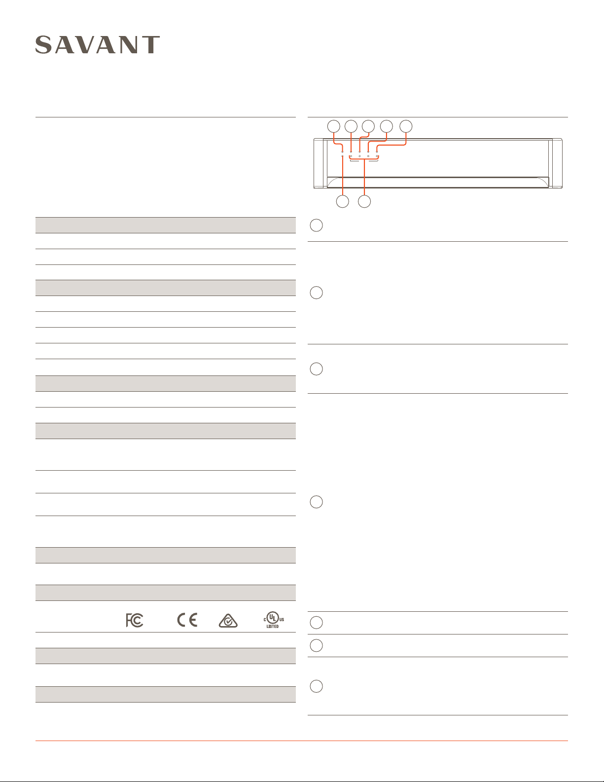
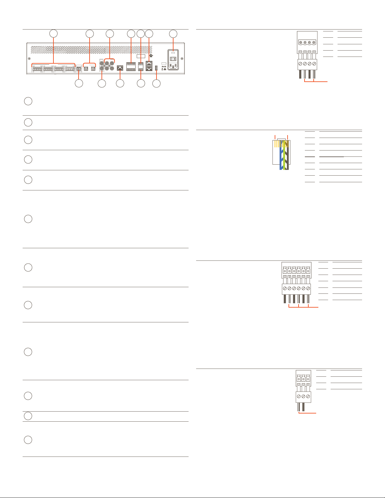
Rear Panel
Speaker
Connections
(4) Speaker output zones.
Uses 4-pin Speaker Connectors.
NOTE: Compatible with 8 ohm or
4 ohm speakers.
Digital
Audio Out
(1) Digital optical preamp output (TOSLINK),
line-level 96kHz/24-bit output, fixed volume.
Digital
Audio In
(2) Digital optical audio inputs (TOSLINK).
Supports up to 96kHz/24-bit digital audio in;
PCM stereo format only.
Analog
Preamp
Output
(1) Analog stereo line output (Left & Right).
Direct Line Level 2.1-VRMS Output.
Analog
Inputs
(2) Analog stereo inputs (Left & Right),
RCA line-level inputs;
22 kΩinput impedance.
Ethernet
8-pin RJ-45 port
10/100/1000 Base-T auto-negotiating port.
Supports Audio Video Bridging (AVB).
Activity LED:
Green Blinking: Activity (Rx/Tx)
O: No Activity.
Link LED:
Green Solid: Ethernet Link is established.
O: Ethernet link is not established.
IR
(6) IR Ports.
Uses 6-pin IR Connectors to send IR signals to
control devices with an IR input or IR receiver
via an IR flasher (5V tolerant only). See IR Wiring
section for important precautions regarding IR
functionality before making any connections.
Relay
3-pin Control Connector.
See Relay Wiring for pinouts.
Normally Open (NO) Normally Closed (NC) to
control devices requiring basic on/o operation.
DC Voltage Max: 30V DC 1A.
GPIO
3-pin Control Connector
See GPIO Wiring for pinouts
GPIO Input: When configured as an input the
processor will look for a low (<0.8V DC) or a high
(>2.4V DC) state.
Minimum 0V DC / Maximum 12V DC.
GPIO Output: When configured as an output, the
port provides a binary output of 0-12V
DC 150mA max.
RS-232
8-pin RJ-45 port used to transmit and receive
serial binary data to and from serial controllable
devices. CTS/RTS handshaking availability based
on component profile. See RS-232 Connections
section for pin-outs.
USB USB 2.0 Type A (reserved for future use)
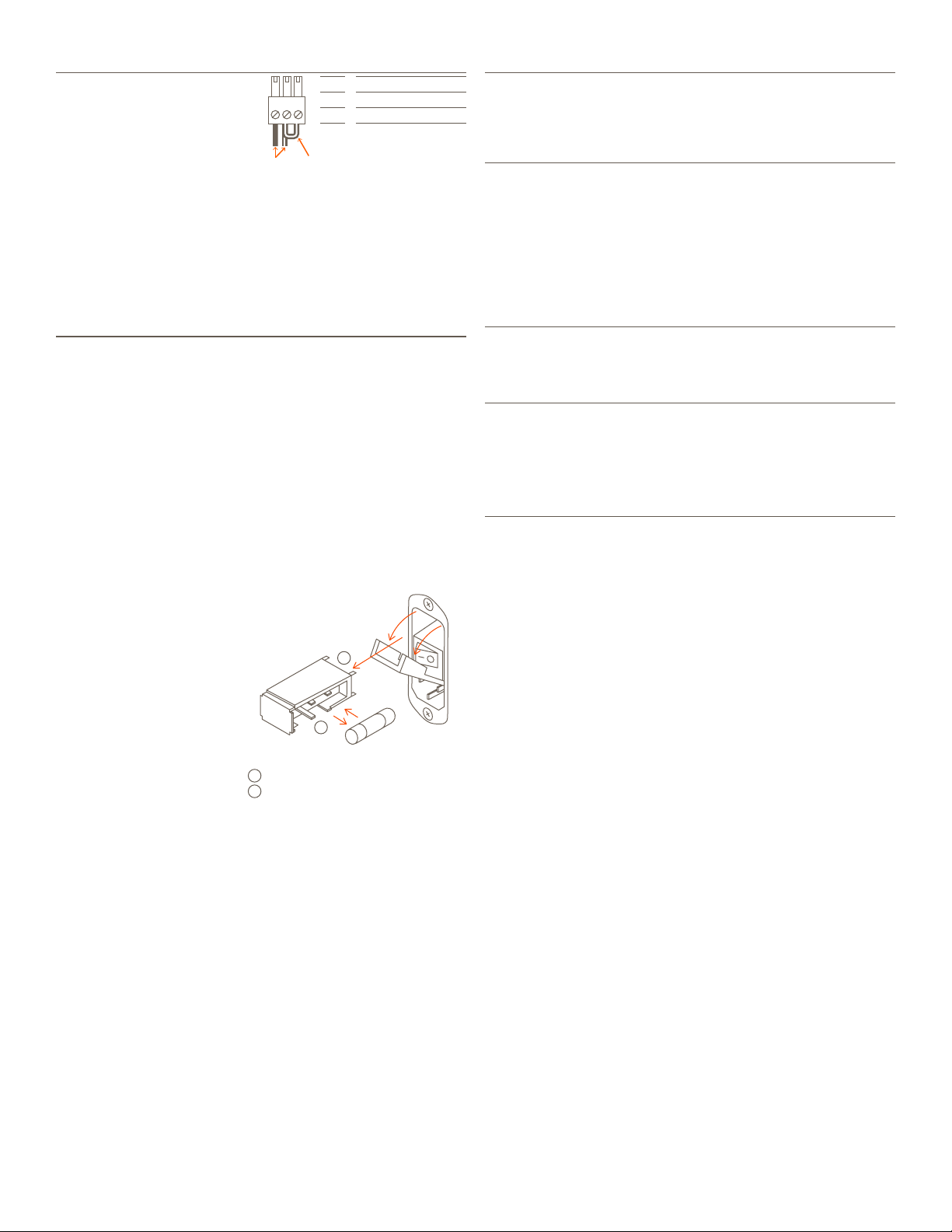
Power Input
100/240V AC (50/60 Hz) 5.7A
Fuse: 250V 10A slow blow fuse; field replaceable
I/O (power switch):
I (On): Powers On the chassis.
O (O): Powers O the chassis.
A
B
C
D
E
F
G
H
I
J
K
L
AV Equipment E475835
Max Current: 10A
100-240 VAC 50/60 Hz
-
Distributed Audio
-
R+L+
Zone 1
-R-L
+
Zone 2 Zone 3
+R+
-L+
-+
-R+
-L
Zone 4 Out In 1
Digital Audio
In 2
+
+
Analog Audio
Out In 1 In 2
Ethernet
R
-4
L
1
-
-
5+
-6+GPIO
G1PD
-
2+
-
IR
3+
Relay
NC CNO
M/N S/N UID
RS232-2
USB
RS232-1
Fuse: 250V, 10A Fast Acting
HIPOT
A
B
C
D
E
F
GH
I
J
K
L
Speaker Connections
-
R +
-
L +
Zone 1
432
1
Pin 1
Pin 2
Pin 3
Pin 4
Right -
Right +
Left -
Left +
Use white stripe
for positive (+)
Speaker wiring connections are made
using 4-pin Speaker Connectors
supplied with the device. The wire slips
into the hole and locks with a screw
located at the top of the connector.
Speaker connectors accept up to
12AWG speaker cable.
NOTES:
– Wire order shown does not represent any wiring standard.
– While not shown in the diagram above, Zones 2 to 4 follow the same
wiring as Zone 1.
RS-232 Connections
Pins 7 and 8 are only required
for CTS/RTS handshaking.
Pin 1
Pin 2
Pin 3
Pin 4
Pin 5
Pin 6
Pin 7
Pin 8
No Connection
No Connection
No Connection
Ground (GND)
Receive (RXD)
Transmit (TXD)
Clear to Send (CTS)
Request to Send (RTS)
Pin 1 Pin 8
RJ-45 Connector
(Gold pins face up)
IMPORTANT: When wiring to
this port, do not connect any
wires within the cable that are
not required for
communication.
NOTES:
– CTS/RTS handshaking is supported for flow control based on the
profile used in the configuration.
– Wire coloring is included to identify the pins used for this
connection. Colors shown do not represent any wiring standard.
– The IP Audio 125 does not support RS-422/485.
RJ-45 to DB9 Adapter: Savant oers RJ-45 to DB9 adapters in a
variety of configurations that can be used for RS-232 control.
Refer to the RS-232 Conversion to DB9 and Pinout Application Note
located on the Savant Customer Community for more information on
RJ-45 to DB9 adapters.
IR Wiring
432
1
-
1 +
-
2 +
65
-
3 + Pin 1
Pin 2
Pin 3
Pin 4
Pin 5
Pin 6
IR 1 -
IR 1 +
IR 2 -
IR 2 +
IR 3 -
IR 3 +
Use white stripe
for positive (+)
IR connections are made using
6-pin IR Connectors supplied with
the device. The wire slips into the
hole and locks with a screw
located at the top of the
connector.
IMPORTANT NOTES:
– Ensure that all IR emitters are within 15 feet (4.6 meters) from the
controller’s location.
– Use of 3rd party blinking IR emitters with Talk Back is not
supported. These types of emitters can draw voltage away from the
IR signal that can degrade IR performance.
– While not shown in the diagram above, IR connections 4 to 6 follow
the same wiring as 1 to 3.
Relay Wiring
32
1
NC NOC
/ / Pin 1 Normally Closed
Pin 2 Common
Pin 3 Normally Open
Relay ports are used when a device is
controlled via a normally open (NO) or
normally closed (NC) relay.
Use white stripe
for positive (+)
1 of 4