Bohle Liftmaster B1 User manual

Operating Instrutions
B1
Liftmaster

Operating Instructions Bohle LiftMaster B1 –Version 1.1 E 1
Introduction
Dear Customer,
Thank you for purchasing the Bohle LiftMaster B1 handling aid.
Please read these operating instructions carefully before start-up. The complete instruction manual
should be kept beside the handling aid at all times.
If you have questions or wish to order spare parts or report problems, please indicate the machine
type and model number.
No part of this instruction manual must be reproduced or processed, duplicated or distributed by elec-
tronic systems in any form or by any means (print, photocopy, microfilm or other procedures) without
prior written consent by Bohle AG.
Subject to technical changes to reflect technical advances.
This document is an English translation of the German original version.
© Bohle AG. All rights reserved.
Table of Contents
Introduction 1
Table of contents 1
EC declaration of conformity 2
1. General safety instructions 3
2. Technical data 5
3. Transport, storage and scope of delivery 6
4. Overview 8
5. Functions, controls 10
6. Work procedure 23
7. Inspection and maintenance 29
8. Troubleshooting 30
Inspection log appendix 31

Operating Instructions Bohle LiftMaster B1 –Version 1.1 E 2
Declaration of Conformity
We hereby declare that handling aid
Model
Liftmaster B1
No.
Date of manufacture
in the version supplied, complies with the relevant provisions:
Supply of Machinery (safety) Regulations 2008
Harmonised standards applicable, in particular
DIN EN 13035-1
DIN EN 13035-2
Bohle does not accept any liability if:
-the handling aid is not used for its intended purpose,
-the handling aid has been modified or altered without authorisation,
-components or spare parts of other manufacturers are used,
-the handling aid is installed or used incorrectly or by unauthorized personnel,
-the handling aid is not serviced regularly,
-the instructions and regulations of this manual are not observed.
Intended use
This Bohle handling aid is designed for transporting and handling glass elements and similar flat ob-
jects with gas-tight surfaces. Any other use is considered to be contrary to its intended use.
Haan, (date) _______________
Edgar Höhn
Technical machines manager, authorised for the compilation of technical documentation
Bohle AG, Dieselstraße 10, D-42781 Haan

Operating Instructions Bohle LiftMaster B1 –Version 1.1 E 3
1. General Safety Instructions
•This handling aid must be set up, operated, and maintained only by authorised, trained
and registered personnel who are familiar with these instructions. Personnel must be
informed about existing
residual hazards.
•We will accept liability for trouble-free operation only if original Bohle spare parts are
used.
•Before use, all safety devices must be checked to ensure that they are correctly in posi-
tion and undamaged.
•To avoid hold-ups, the operator must operate the handling aid
according to these operating instructions and the relevant regulations.
•In addition to the operating instructions, all relevant legal and other binding regulations
concerning accident prevention and environmental protection must be observed.
•When performing maintenance, remove the transport material / glass pane!
•Always wear suitable protective clothing when handling glass.
•Do not make any modifications, additions or conversions to the
handling aid. This particularly applies to safety devices.
Unauthorised alterations and modifications to the handling aid will cause the above EC
Declaration of Conformity to become void. This will then have to be re-issued by the
operator or by an authorised representative.
•Keep these operating instructions available beside the handling aid.
•Never release the vacuum in the vacuum lifter while transporting an object.
•The handling aid must be used only on level ground with sufficient load bearing capaci-
ty.
•Please follow the operating instructions of the vacuum lifter being used. The operating
instructions for the vacuum lifter remain valid!
•Regularly check the suction pads, pressure gauge and vacuum hoses for damage. Im-
mediately replace damaged parts!
•Using the equipment in areas with potentially explosive atmospheres (ATEX areas) is
strictly forbidden.
•It is also strictly forbidden to stand or walk under a suspended load! Risk of injury!
•Never intervene in the work area around the machine, either manually or using aids,
while the handling aid is in use. Do not bypass any safety devices. Risk of injury!
•The operator must ensure that no unauthorised persons work with the handling aid or
enter the surrounding area. Risk of injury!
•No one must be lifted or carried with this handling device!
•The equipment must not be used in windy conditions (maximum wind force 4 Beaufort),
or in snow or rain. Depending on the shape and size of the workpiece, operation may
have to be stopped.
•Never leave the handling aid unattended with a suspended load.

Operating Instructions Bohle LiftMaster B1 –Version 1.1 E 4
•Check the condition of the steel cable in the cable winch every day. In case of damage,
operation must be suspended immediately.
•While carrying a load, the steel cable must be kept tensioned to prevent uncontrolled
unwinding of the cable.
•Use the equipment only in combination with lifting devices which have been approved
by Bohle for use with the handling aid.
•It is strictly forbidden to operate the handling aid under the effect of medication which
affects reaction speed or cognitive ability, or under the effect of drugs and alcohol!
•If safety devices have been removed in the course of repair work, the machine must not
be operated again until all safety devices have been attached and checked for correct
function.
•Never use more than three counterweights at a time.
Warning against hand
injuries
Wear protective shoes
Wear protective glasses
Do not stand or walk
under the suspended
load
Wear hair net
Wear protective gloves
Warning against danger spot
Read instruction manual

Operating Instructions Bohle LiftMaster B1 –Version 1.1 E 5
2. Technical Data
Total height with vacuum lifter [mm] max.
2600
Total width [mm] max.
1085
Total length [mm] max.
2405
Glass thickness [mm] min.
3
Max. load [kg]*
180
Working temperature range [°C]
10 –40°
Weight with vacuum lifter, incl. counterweight [kg] approx.
120
Option: Counterweight [kg per piece]
25
* considering the loading cases and diagrams starting from Page 22

Operating Instructions Bohle LiftMaster B1 –Version 1.1 E 6
3. Transport, Storage, and Scope of Delivery
The handling aid is supplied mounted on a pallet.
Scope of delivery includes the assembled handling aid, a vacuum lifter, and the operating instructions.
It is essential to check the delivery for completeness and for damage. Transport dam-
age must be reported to the carrier (shipping agent, train operator, etc.) immediately
and in writing.
Do not use the equipment if damaged!

Operating Instructions Bohle LiftMaster B1 –Version 1.1 E 7
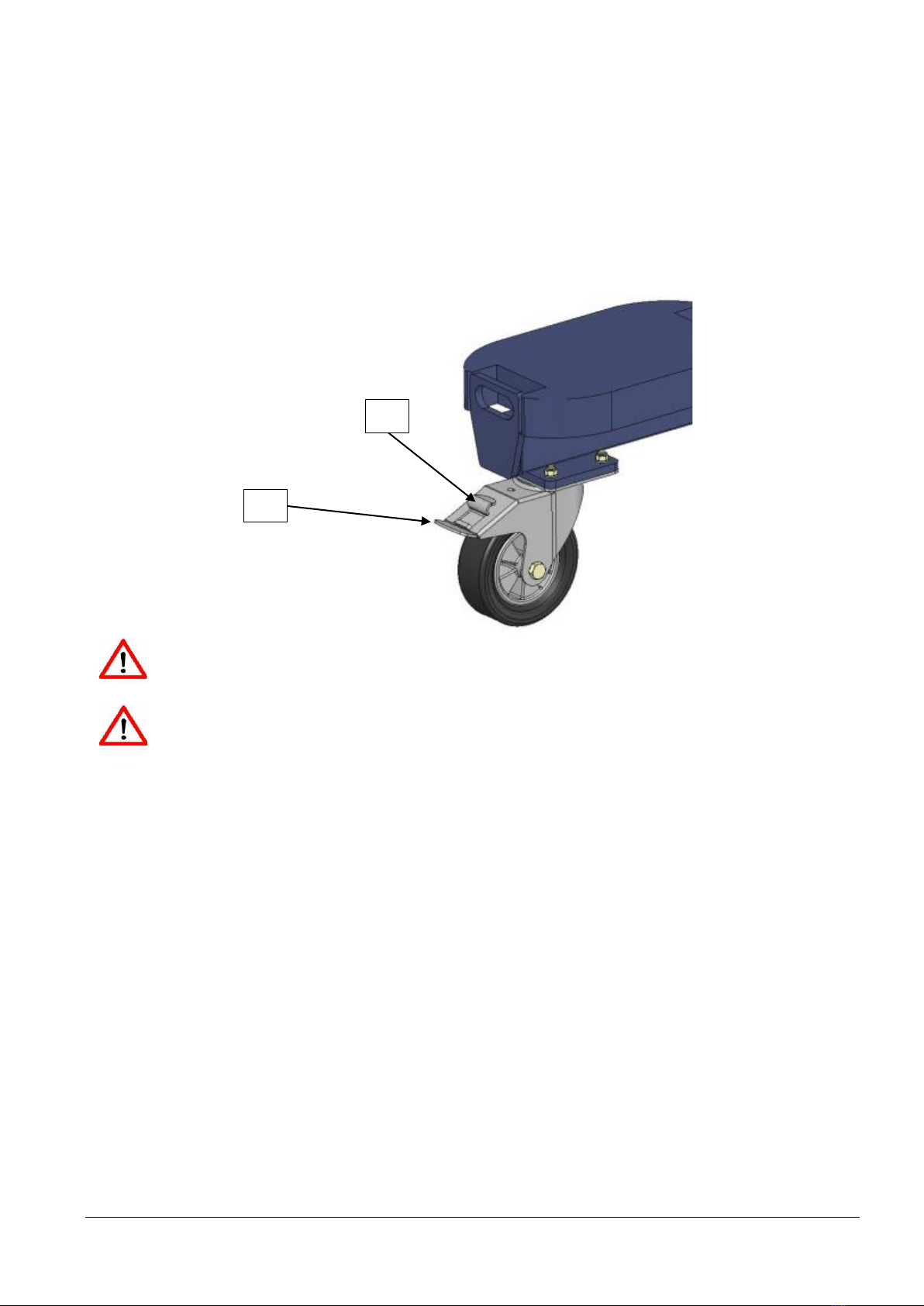
Remove all transport locks and packaging material and have a second person assist in removing the
handling aid from the pallet.
Unlock rear wheel "a" and loosen star knob "b".
The Liftmaster is now ready for use.
a
b

Operating Instructions Bohle LiftMaster B1 –Version 1.1 E 8
4. Overview
01: Vacuum lifter
02: Cable winch "Vacuum lifter up/down" function SP 88.B0013
03: Star knob "Fix skid guide" function
04: Front wheel SP 88.B0106
05: Foot pedal "Rotate mast" function
06: Rear wheel with brake SP 88.B0107
07: Counterweight BO 88.025
08: Handle
09: Mast
10: Steel cable SP 88.B0015
11: Unlock "Tilt mast" function
12: Unlock "Adjust handle" function
1
2
3
4
7
6
9
8
10
5
11
12

Operating Instructions Bohle LiftMaster B1 –Version 1.1 E 9
13: Lock pin "Adjust counterweight" function
14: Rubber pad
15: Star knob "Adjust front wheels" function SP 88.B0115
16: Swivel handle "Manipulate vacuum lifter" function
13
15
16
14

Operating Instructions Bohle LiftMaster B1 –Version 1.1 E 10
5. Functions/controls
The operator can bring the Liftmaster into different positions for lifting and placing loads.
These positions are then locked using the locking elements (e.g. lock pin, brake)
After an adjustment, always ensure that related locking element is released.
Always carry out only one adjustment procedure at a time. (Example: position the
Liftmaster first, then adjust the load height).
When parking the Liftmaster, always apply the rear wheel brake.
Except when transporting the Liftmaster, always pull out and lock the counterweight
in order to obtain maximum leverage.
5.1 Vacuum lifter functions
Follow the operating instructions of the vacuum lifter!
Liftmaster B1 is operated exclusively with the supplied vacuum lifter Type BO B18DM4.
The vacuum lifter can be uncoupled from the Liftmaster and used
independently.

Operating Instructions Bohle LiftMaster B1 –Version 1.1 E 11
Removing and mounting the vacuum lifter
The vacuum lifter is held on the skid of the Liftmaster by pin 19.
For removal, crank the vacuum lifter to an ergonomically suitable height (in horizontal position).
Release lock pin 17 and turn through 90° so that it remains unlocked.
Push ratchet 18 towards the mast, raise the vacuum lifter 30 mm and pull it out of the guide.
For mounting, crank the skid to an ergonomically suitable height.
Push the pin of the vacuum lifter fully in (horizontal position) and lower the vacuum lifter till it can be
heard to engage. Check that the vacuum lifter is correctly seated. Release lock pin 1 by turning
through 90° and then turning the vacuum lifter until the lock pin engages.
17
18
19
18

Operating Instructions Bohle LiftMaster B1 –Version 1.1 E 12
"Rotate vacuum lifter" function
The vacuum lifter can be turned continuously through 360° with or without load.
Remember that the diagonal dimensions of the load are longer than the lateral dimen-
sions. Make sure that the load has sufficient room for turning without touching the
operator or hitting against the Liftmaster or nearby objects.
Grasp the load at the centre, otherwise substantial torsional forces will be created.
Pull lock pin 17 and turn the vacuum lifter slowly into the desired
position.
Caution! Danger of crushing!
To stop movement of the load automatically at each quarter turn,
release the lock pin immediately after rotation has started, so that the lock pin engages at the
next locking point. The lock pin should
always remain engaged when no turning movement is required.
This will prevent damage to the load and injuries to the operator.
Rotate the load only if the vacuum lifter is fully connected to the Liftmaster!
Never engage the lock pin while the vacuum lifter is turning –with or without load.
This will avoid severe wear and, in the worst case, accidents.
17
Operating Instructions Bohle LiftMaster B1 –Version 1.1 E 13
5.2 Liftmaster functions
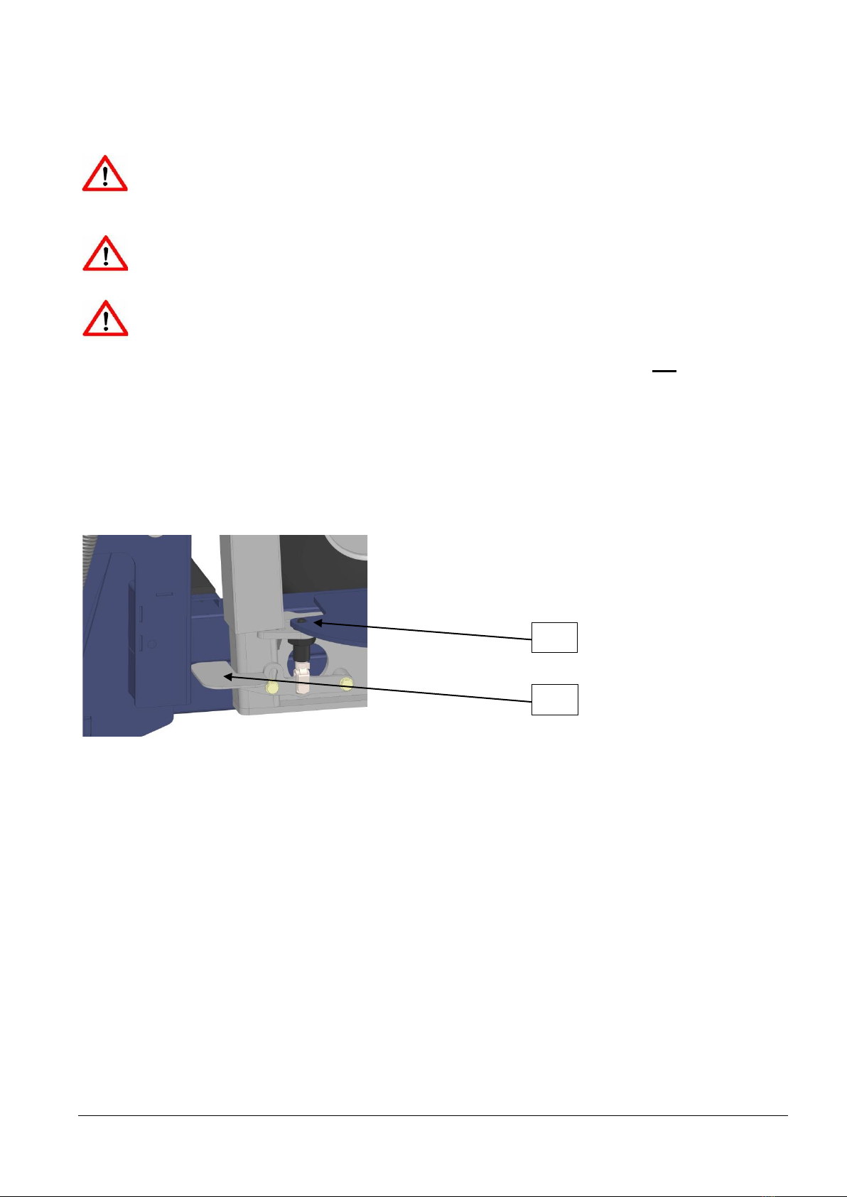
"Rear wheel brake" function
This function is used to secure the Liftmaster by preventing undesired or spontaneous movements.
The rear wheel brake is applied by stepping on brake pedal a. and released by stepping on release
pedal b.
Please note that this brake is an immobiliser.
It is not suitable for braking the carriage while moving.
When parking the Liftmaster, always apply the rear wheel brake.
b.
a.
Operating Instructions Bohle LiftMaster B1 –Version 1.1 E 14
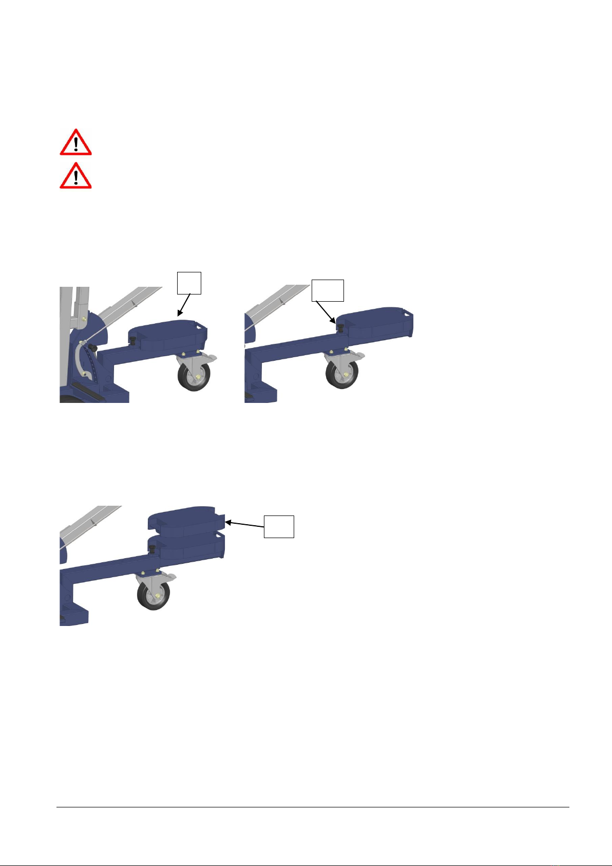
"Counterweight" function
This function is used to improve the leverage under load and to ensure
stability.
For the counterweight, 3 counterweights are supplied as standard.
Lock pin 20 must always be locked.
Refer to the loading cases and diagrams starting from Page 22
To pull out the counterweight: Release lock pin 20, pull out counterweight 7, lock the lock pin 20.
Counterweight in initial position Counterweight in work position
Placing an optional additional weight
7
20
21
Operating Instructions Bohle LiftMaster B1 –Version 1.1 E 15
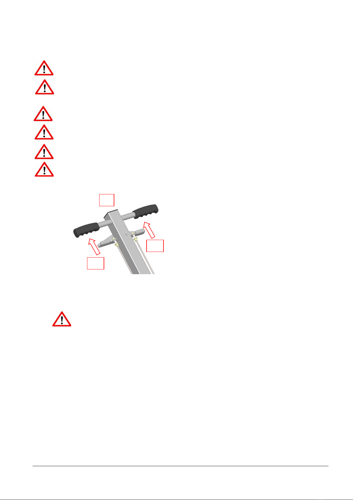
Swivel handle "Manipulate vacuum lifter" function
This function is used to manipulate the vacuum lifter.
Locking holes 22 are provided for fixing the position. To move the vacuum lifter, unlock the lock pin 23
and turn through 90°. Then move swivel handle 24 to the desired position. If the vacuum lifter is to be
left in one position over long periods, engage lock pin 23.
Make sure that the swivelling area is free of obstacles. Risk of collision and breaking
glass!
24
22
23
Operating Instructions Bohle LiftMaster B1 –Version 1.1 E 16
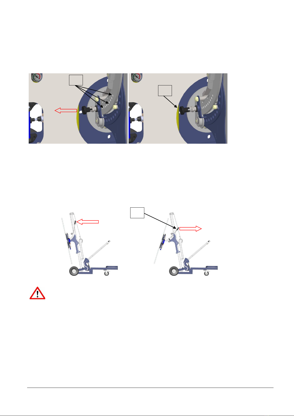
"Tilt mast" function
For lifting and placing loads in front of the front wheel axle of the Liftmaster, the mast can be tilted and
locked in various positions.
Refer to the load diagrams on Page 24ff.
Tilt the mast only when positioned "parallel to the front axle"
After an adjustment, always ensure that related locking element is released.
Always carry out only one adjustment procedure at a time. (Example: position the
Liftmaster first,then adjust the load height).
When parking the Liftmaster, always apply the rear wheel brake.
Except when transporting the Liftmaster, always pull out and lock the counterweight.
Make sure that the tilting range is free of obstacles. Risk of
collision and breaking glass!
To tilt the mast, use lever 12 to bring handle 8 into an ergonomic position and lock it.
Use lever 11 to tilt the mast while at the same time raising handle 8.
When tilting, be careful if the load's centre of gravity is moving over the front
axle.
12
11
8

Operating Instructions Bohle LiftMaster B1 –Version 1.1 E 17
The handle is tilted backward by following the same procedure in the reverse order.
Mast in initial position "parallel to front axle"
Mast tilted
Operating Instructions Bohle LiftMaster B1 –Version 1.1 E 18
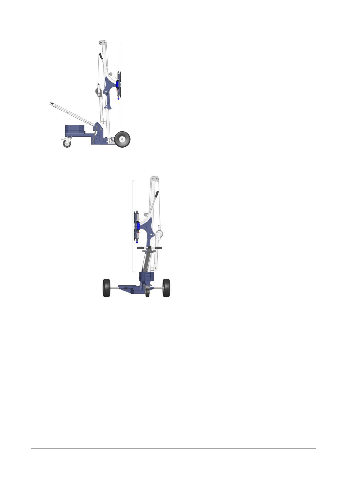
"Rotate mast" function
This function is used to bring loads that have been lifted in front of the Liftmaster into the transport
position.
After an adjustment, always ensure that the related locking element is released.
Always carry out only one adjustment procedure at a time. (Example: adjust the Lift-
master first,then adjust the load height).
When parking the Liftmaster, always apply the rear wheel brake.
Except when transporting the Liftmaster, always pull out and lock the counterweight.
Rotate the mast only when not tilted, i.e. it is in vertical position.
Make sure that the swivelling area is free of obstacles.
Risk of collision and breaking glass!
Rotate the mast only if the load is located at the mast (the load must not be swivelled
out)
To turn the mast, lock pin 25 must be released by stepping on foot pedal 26. Rotate the mast counter-
clockwise.
The mast can be locked again in two different positions:
-Parallel to the front axle to lift and place glass panes,
-Across the front axle, vacuum lifter to the left, as for transport position,
25
26
Operating Instructions Bohle LiftMaster B1 –Version 1.1 E 19
Mast position parallel to front axle (Lifting and placing loads)
Mast position across front axle (Transporting loads)
Table of contents
Other Bohle Lifting System manuals


Popular Lifting System manuals by other brands

Guardian
Guardian Voyager Portable Ceiling Lift System 98000 Installation instructions manual

Wesco
Wesco POWER-LIFT STACKER Operating instructions and parts manual

Strongline
Strongline XK1025A instruction manual

BrandSafway
BrandSafway Spider SC1000 Series Service manual

BLACKHAWK!
BLACKHAWK! Minipost MPT60 instruction manual

Bend-Pak
Bend-Pak XPR-10XLS-LP-181 Service manual

Bend-Pak
Bend-Pak HDS-14 Installation and operation manual

SAFE-TECH
SAFE-TECH Palift MK3 user manual

Bend-Pak
Bend-Pak Clearfloor 10APX Service manual

Air Lift
Air Lift loadlifter 5000 installation guide

ARJO HUNTLEIGH
ARJO HUNTLEIGH Minstrel Instructions for use

PRO LIFTS
PRO LIFTS VMB TE-074 Operating instructions & user manual


