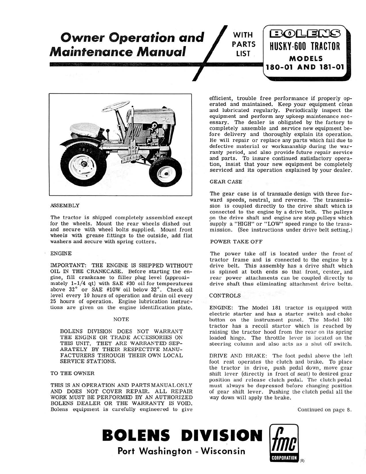
(]30[6[3~
HUSKY
-
600
TRACTOR
Owner
Operation
and
Maintenance
Manual
MODELS
--
-
--
----
-----------180
-
01
AND
181
-
01
WITH
PARTS
LIST
NlSEMBLY
The
tractor
is
shipped
compl
etely a
ss
e
mbled
ex
ce
pt
for
th
e
wh
e
els.
Mount
the
rear
whe
els
dished
out
and
se
c
ure
with whe
el
bolts
supplied.
Mount
front
wheels
with
grease
fittin
gs
to
th
e
outside
,
add
flat
washers
and
secure
with
spring
cotters.
ENGINE
IMPORTANT:
THE
ENGINE IS
SHIPPED
WITHOUT
OIL
IN
THE CRANKCASE.
Before
startin
g
the
en-
g
ine,
fill
crankcase
to
filler
plug
lev
el
(approxi-
mately
1-
1/4
qt
) with SAE #30
oil
for
temperatures
above
32°
or
SAE #lOW
oil
below 32°.
Check
oil
le
vel
every
10
hours
of
operation
and
drain
oil
every
25
hours
of
operation.
Eng
ine
lubrication
instruc-
tions
are
g
iv
en on
th
e
en
g
ine
identific
a
tion
plate
.
NOTE
BOLENS DIVISION DOES NOT WARRANT
TilE
ENGINE OR TRADE ACCESSORIES
ON
THIS UNIT. THEY ARE WARRANTED
SEP-
ARATELY BY
THEIR
RESPECTIVE
MANU-
FACTURERS THROUGH
THEIR
OW
N LOCAL
SERVICE STATIONS.
TO THE OWNER
THIS IS
AN
OPERATION AND
PARTSMANUALONLY
AND
DOES NOT COVER
REPAIR
.
ALL
REPAIR
WORK MUST BE
PERFORMED
BY
AN
AUTHORIZED
BOLENS
DEALER
OR
THE
WARRANTY
IS
VOID.
Bolens
equipment
is
carefully
engineered
to
give
efficient,
trouble
free
performance
if
properly
op-
erated
and
maintained.
Keep
your
equipment
clean
and
lubricated
regularly.
Periodically
inspect
the
equipment
and
perform
any ,
upkeep
maintenance
nec-
essary.
The
dealer
is
obligated
by
the
factory
to
completely
assemble
and
service
new
equipment
be-
fore
delivery
and
thoroughly
explain
its
operation.
He
will
repair
or
replace
any
parts
which
fail
due
to
defective
material
or
workmanship
durin
g
the
war-
ranty
period,
and
also
provide
future
repair
service
and
parts
. To
insure
continued
satisf
a
ctory
opera-
tion,
insist
that
your
new
.
equipment
be
c
omplet
ely
serviced
and
its
operation
explained
by
your
dealer.
GEAR CASE
The
gear
case
is
of
transaxle
design
with
thre
e
for-
ward
speeds,
neutral,
and
reverse
.
The
transmis
-
sion
is
c
oupled
directly
to
the
drive
shaft
which
is
conne
c
ted
to
the
engine
by a
drive
be
lt.
Th
e
pulleys
on
the
drive
shaft
and
en
g
ine
are
step
pulleys
which
'supply a "HIGH"
or
"LOW"
speed
ran
ge
to
the
trans-
mission.
(S
ee
in
s
tru
c
tions
under
driv
e be
lt
se
ttin
g.)
POWER TAKE
OFF
The
power
take
off
is
located
under
th
e
front
of
tra
c
tor
frame
and
is
c·
onnected
to
the
eng
in
e by a
driv
e be
lt.
This
assembly
has
a
dri
ve
shaft
which
is
s
plin
ed
at
both
ends
so
th
at
fr
o
nt,
ce
nt
e
r,
and
r e
ar
power
attachments
can
be c
oupl
ed
dire
c
tly
to
driv
e
shaft
thus
e
liminatin
g
atta
clmte
nt
dri
ve
belts.
CONTROLS
ENGINE:
The
Model
181
tra
ctor
is
eq
uipped with
electric
starter
and
has
a
start
er
swit
ch
and choke
button
on
th
e
instrument
p
ane
l.
Th
e
Mo
del 180
tractor
has
a
recoil
st
a
rt
er which is
reac
hed by
raisin
g
the
tra
c
tor
ho
od
fr
om the
rear
on its
sprin
g
lo
a
ded
hin
ge
.
Th
e
throttl
e l
ever
is
loc
at
ed on the
steerin
g c
olumn
a
nd
al
so
ac
ts
as
a
shut
off switch.
DRIVE
AN
D BRAKE:
Th
e
fool
pedal
above
th
e l
eft
foot r
es
t
op
er ates
th
e clutch and
brak
e. To
pl
ace
th
e
tra
c
tor
in
dri
ve,
push p
eda
l down, move
ge
ar
s
hift
l
eve
r
(dire
c
tly
in
front
of
seat)
to
d
es
ir
ed
ge
ar
po
s
ition
and r el
ease
c
lut
ch peda
l.
The clu
tc
h pedal
must
always
be de
press
ed before changing
position
of
gear
shift
lever.
Pushin
g
th
e c
lut
ch pedal
all
the
way down
will
apply
th
e
brak
e.
Cont
inued
on p
age
8.
BOLENS
DIVISION
fmc
Port
Washington
-
Wisconsin