Jun 30/01
21-00-00 Page 1
EFFECTIVITY: All
z
SD3-60 AIRCRAFT MAINTENANCE MANUAL
AMM21-00-00 1.0.0.0AIR CONDITIONING - DESCRIPTION AND OPERATION
1. General
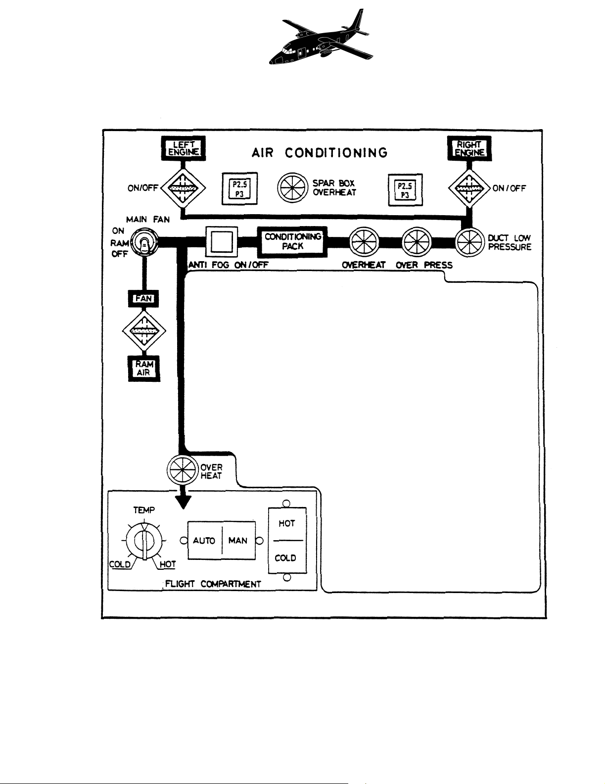
Refer to Figure 1.
A single air conditioning system supplies conditioned air to the flight and passenger
compartments with separate temperature control for each.
The system derives its hot air from bleeds on both engines but will continue to work, with reduced
performance on a supply from one engine only.
2. Bleed air conditioning
Refer to Figure 1. Refer to Figure 2 (Sheet 1).
Bleed air is taken via fixed orifices from the P2.5 and P3 bleed connections on each engine. At
low power settings, when the P3 bleed pressure is below 35 p.s.i.g., the temperature control
valve (TCV) is fully open admitting P3 bleed air only, to operate the system. At high power
settings, when pressure in the P3 bleed line exceeds 35 p.s.i.g. a pressure switch operates to
initiate modulation control via the solenoid selector valve and temperature sensor (TS), initially
closing the TCV. Due to the absence of P3 pressure, the check valve in the P2.5 bleed line
opens, maintaining system requirements on P2.5 bleed air only. Should the temperature in the
common bleed line fall to below 300° F whilst operating on P2.5 bleed air, a temperature sensor
(TS) will modulate the TCV to open, allowing P3 bleed air to mix with P2.5 thus maintaining the
bleed air temperature above 250° F. To prevent spurious over-pressure warning being caused by
a cold TS, a time delay is included to postpone the opening of the TCV until 10 seconds after the
HA/SOV is selected open.
Downstream of the TS air passes through a hot air shut-off valve (HA/SOV), a venturi and a
check valve to a common line. The check valves in each half system prevent cross-flow between
engines and the dumping of all bleed air, should either duct fracture.
Air in the common line passes to a refrigeration unit consisting of a dual heat exchanger and a
three-wheel air cycle machine (ACM). In the heat exchanger the bleed air is cooled in the primary
section, compressed and then intercooled in the secondary section. The cooling medium in the
heat exchanger is ambient air driven through the heat exchanger by the fan of the ACM. The
NACA inlet for ambient air is located in the fuselage roof fairing. A flap at the top rear is spring-
loaded closed and will open inwards to supplement the supply during static running should the
demands of the ACM cause a partial depression within the fairing. A lip at the rear of the flap (aft
hinge point) provides for aerodynamic assistance of flap closure during flight (in addition to spring
action).
From the secondary section of the heat exchanger, the bleed air is ducted to the turbine inlet and
to one half of a dual bypass valve; the outlets from both units combine and deliver the air to a
water separator. The cooled air from the secondary section expands in the turbine and produces
a low temperature and condensed mixture (fog); it also provides the power to drive the
compressor and the fan. The water separator coalesces the fog into drops which, when