manuals.online logo
Brands
  1. Home
  2. •
  3. Brands
  4. •
  5. Borglocks
  6. •
  7. Lock
  8. •
  9. Borglocks BL2005 Configuration guide

Borglocks BL2005 Configuration guide

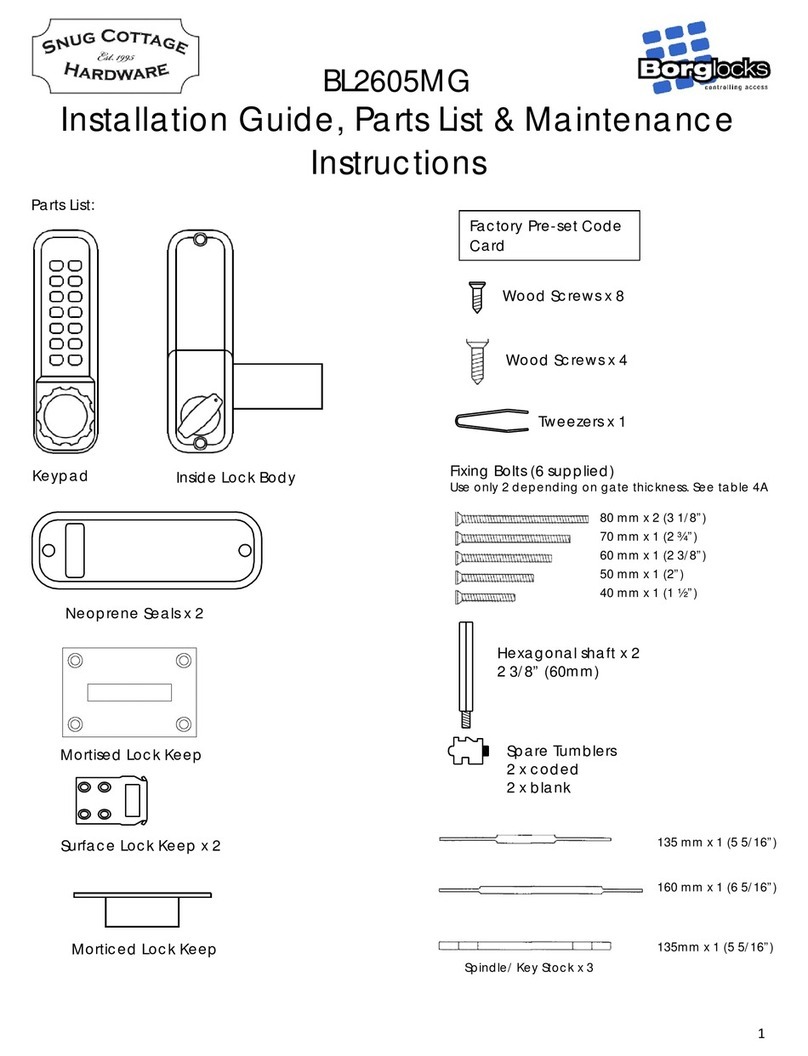
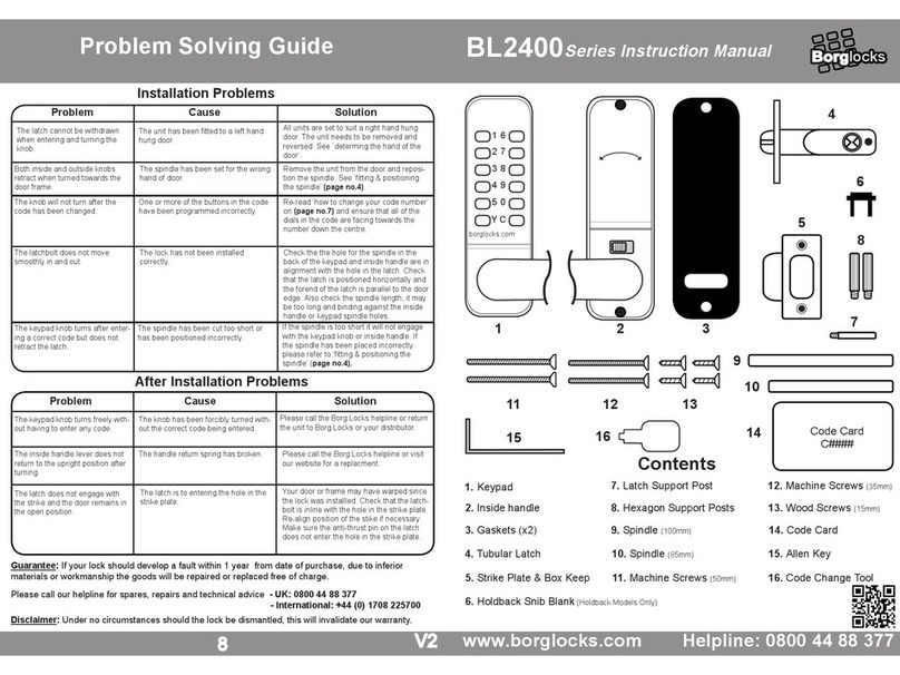
Parts List
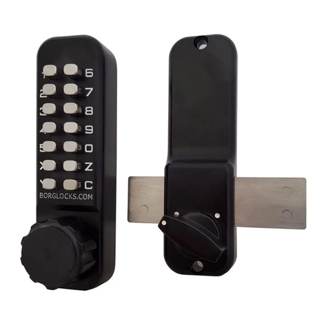
Keypad
Inside Handle
Neoprene seals x2
Spindles (Only one is used)
Surface lock keep
Morticed lock keep
Tweezers (For code changing)
Fixing bolts. 4 Supplied
Spare tumblers. 2 x Coded
2 x Uncoded
Code card
(1)
(2)
(3)
(4)
(5)
(6)
(7)
(8)
(9)
(10)
Please make sure you have received all
the following parts:
BL2005
3. Latch Support Post
4. Positioning the Spindle
Installation
Check the Hand of your door
1.
2. Apply the Template
Special Notes
Positioning and Fixing the Latch
Before commencing installation, check that all
parts are workly correctly: Press the code
according to the code card and then the knob
should turn and return easily under spring
pressure. If you intend to change the code, you
should do so before installing the lock. See the
code chain instructions.
Make sure that the inside handle moves freely.
Check that the snib will engage and hold the
handle in the "latch-open" position if it's a model
with a latch stopper
Check that the latch bolt moves freely by pressing
at the end and also by turning the flat spindle in
the latch cam
Select the spindle to suit the thickness of the door.
Insert the spindle through the slot in the door and
makes sure it engages the latch correctly - (See
Diagram)
When fitting an inside handle to a left-hand door, the
blue screw must go into the right-hand hole and vice
versa.
Your door is
right-handed, if
viewed from the
outside, the hinges
are on the right
Tape the template to the door. Make
sure you fold it along the line.
Mark and drill all six 10mm holes.
Use a chisel to clear the line of 4 x 10mm
holes into a single slot.
Mark a central point on the "centre line of latch" on
the door edge.
Drill a 25mm hole x 85mm deep.
Insert the latch into the hole, and draw around the
face plate.
Remove the latch and cut a 3mm rebate so that
the face plate will fit flush with the door.
Secure the latch with the wood screws.
5. Fixing the Lock How to change your code number
6. Fitting the Strike Plate
7. The Snib Function
Cut the fixing bolts to suit the door thickness,
allowing at least one threaded section to screw
into the keypad.
Hold the keypad and the inside handle, with the
seals, onto the door with the spindle in position.
Using the fixing bolts, screw everything together
through the top and bottom holes of the inside
handle. Before final tightening, make sure the lock
is vertical, and test the mechanism to ensure that
it is all moving easily.
DO NOT CLOSE THE DOOR UNTIL YOU'RE SURE THAT
THE CODE WORKS.
DO NOT over tighten the fixing bolts. This may cause
distortion and poor operation.
Position the strike plate on the door so that it lines up
with the flat of the latcholt, NOT THE PLUNGER.
Mark the inner and outer edges of the strike plate and
cut a 1mm rebate so that it fits flush with the surface
of the door frame.
Drill or cut a recess for the latchbolt.
Fit the strike plate using only wood screw to ensure
it's positioned accurately. The latch bolt, and not the
plunger, should enter the aperature easily and be held
without too much 'play'. When satisfied, secure the
strike with the second screw.
The 'Hold-open' model is equipped with a snib on the
inside handle. This enables the latchbolt to be held
open when required.
If the snib function is not required, you can remove it by
unscrewing the 4 screws, one from each corner, (2 long & 2
short) from inside the backplate. This will enable the metal
plate, the snib, a small spring & a ball bearing to be removed.
Please note that the metal plate, only needs to be replaced
plus the enclosed plastic clip to cover the aperture.
it is all moving easily.
DO NOT CLOSE THE DOOR UNTIL YOU'RE
SURE THAT THE CODE WORKS.
DO NOT over tighten the fixing bolts. This may
cause distortion and poor operation.
Position the strike plate on the door so that it lines up with
the flat of the latchbolt, NOT THE PLUNGER.
Mark the inner and outer edges of the strike place and cut
a 1mm rebate so that it fits flush with the surface of the
door frame.
Drill or cut a recess for the latchbolt
Fit the strike plate using only wood screw to ensure it's
positioned accurately. The latch bolt, and not the plunger,
should enter the aperature easily and be held without too
much 'play'. When satisfied, secure the strike with the
second screw.
N.B The plunger beside the
latchbolt deadlocks the latchbolt
and protects against manipulation.
It must not enter the strike plate
aperture when the door is closed.
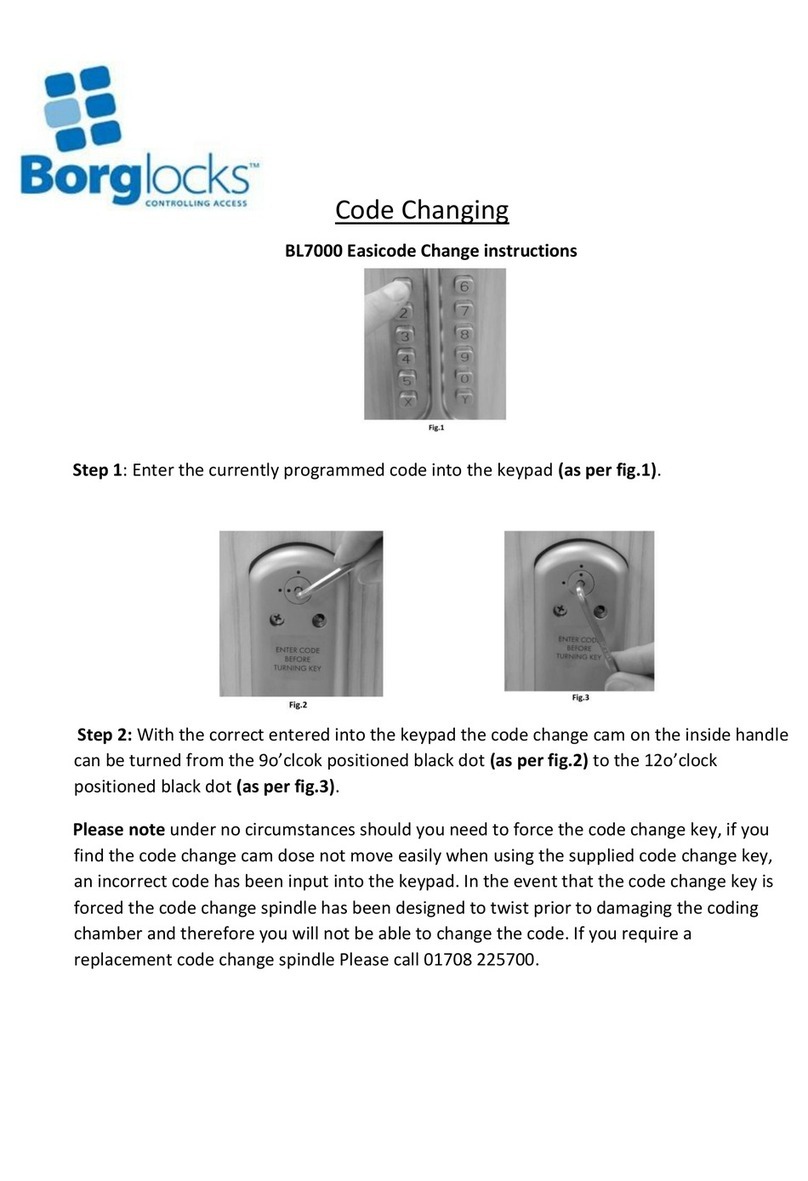
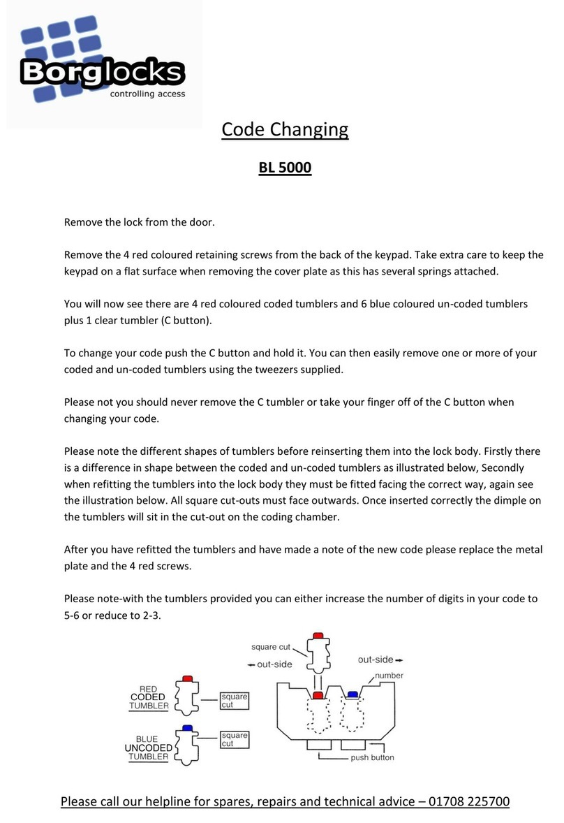
Remove the lock from the door.
Remove the 4 retaining screws from the back of
the keypad. Take extra care to keep the keypad on
a flat surface, when you are removing the plate
due to all of the small components inside.
You will now see that there are 5 red coloured
coded tumblers & 8 blue coloured, uncoded
tumblers plus 1 clear tumbler ('C' button).
To change your code, push the 'C' button down
and hold it. You can then easily remove one or
more of your coded & uncoded tumblers, using the
tweezers supplied.
Please note you should never remove the 'C' tumbler.
Please note the different shapes of tumblers,
before reinsterting them into the lock body. Firstly,
there is a difference in shape between the coded &
uncoded tumblers into the lock body, they must be
fitted facing the right way.
After you have refitted the tumblers and made a note
of the new code, please replace the metal plate with
the 4 screws.
Please note, with the spare tumblers provided, you
can either increase the number of digits in your
code to 6 or 8 or reduce to 4.
1)
2)
3)
4)
5)
6)
7)
8)
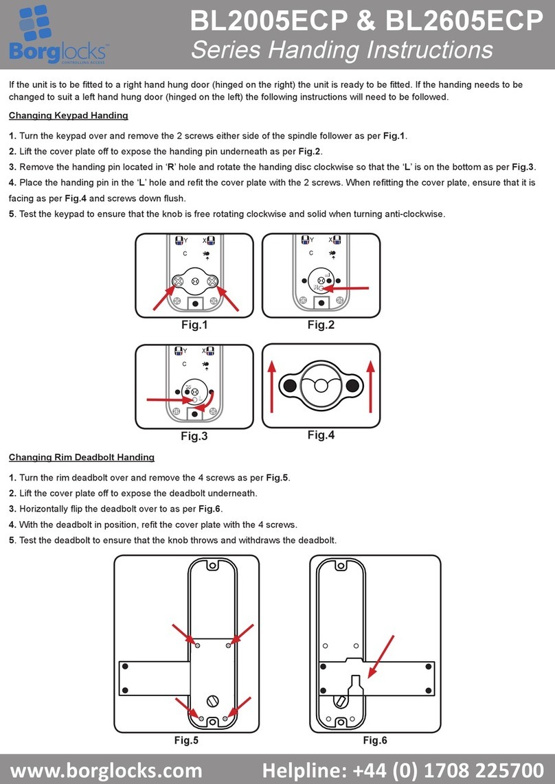
Lay the keypad on a table as shown on drawing below. Turn the bolt handle towards the left.
Turn over the bolt as shown in the drawing below
and replace the plate and screws removed earlier

Other Borglocks Lock manuals

Borglocks BL2615MG Configuration guide

Borglocks

Borglocks BL2615MG Configuration guide

Borglocks BL 2605 MG Pro Configuration guide

Borglocks

Borglocks BL 2605 MG Pro Configuration guide

Borglocks BL2005ECP Series User manual

Borglocks

Borglocks BL2005ECP Series User manual

Borglocks BL2605MG User manual

Borglocks

Borglocks BL2605MG User manual

Borglocks BL3030ECP User manual

Borglocks

Borglocks BL3030ECP User manual

Borglocks BL2615MG Configuration guide

Borglocks

Borglocks BL2615MG Configuration guide

Borglocks BL7000 Easicode User manual

Borglocks

Borglocks BL7000 Easicode User manual

Borglocks BL2605MG Configuration guide

Borglocks

Borglocks BL2605MG Configuration guide

Borglocks BL 5000 User manual

Borglocks

Borglocks BL 5000 User manual

Borglocks BL2400 Series User manual

Borglocks

Borglocks BL2400 Series User manual

Borglocks BL4409 User manual

Borglocks

Borglocks BL4409 User manual

Borglocks BL2701 Quick guide

Borglocks

Borglocks BL2701 Quick guide

Popular Lock manuals by other brands

JNF 20.937 quick start guide

JNF

JNF 20.937 quick start guide

HES 9600 GENESIS installation instructions

HES

HES 9600 GENESIS installation instructions

G-U BKS detect3 B 31 Series Assembly instructions

G-U

G-U BKS detect3 B 31 Series Assembly instructions

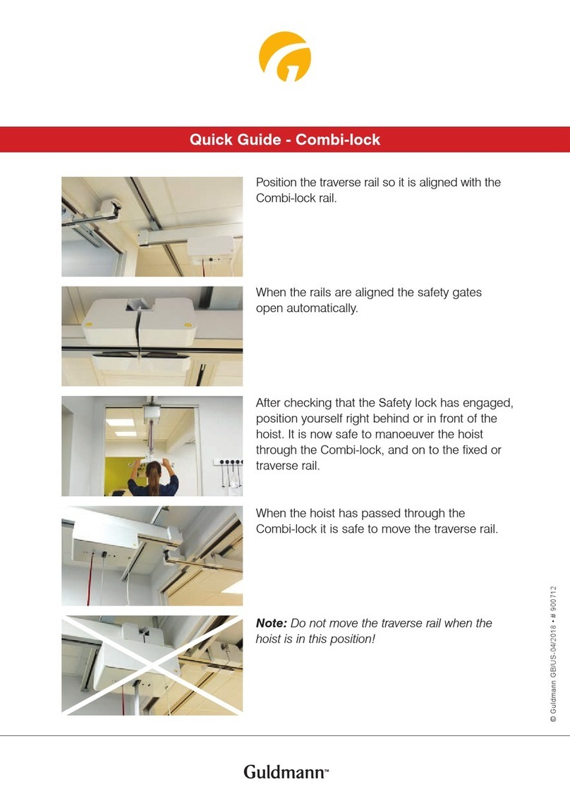
Guldmann Combi-lock quick guide

Guldmann

Guldmann Combi-lock quick guide

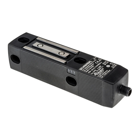
schmersal MZM 100 AS operating instructions

schmersal

schmersal MZM 100 AS operating instructions

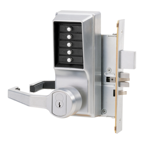
Kaba Simplex 8100 Series installation instructions

Kaba

Kaba Simplex 8100 Series installation instructions

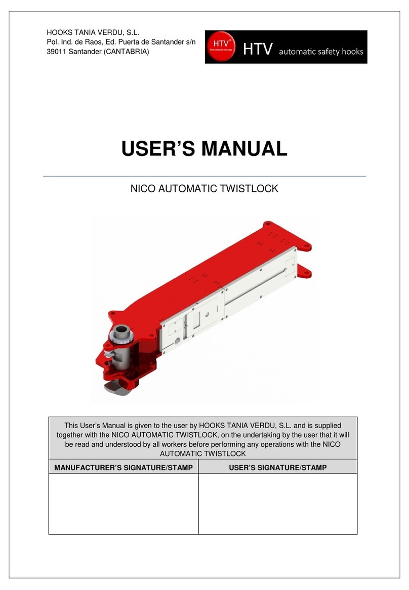
HTV NICO user manual

HTV

HTV NICO user manual

Chamberlain MG 1300 Wiring & specifications

Chamberlain

Chamberlain MG 1300 Wiring & specifications

ADI PRO 0E-UNISTRIKE installation instructions

ADI PRO

ADI PRO 0E-UNISTRIKE installation instructions

Schlage CO-100 installation instructions

Schlage

Schlage CO-100 installation instructions

ZKTeco AL10B user manual

ZKTeco

ZKTeco AL10B user manual

SITEMA KRGP Series operating manual

SITEMA

SITEMA KRGP Series operating manual

Simons Voss Technologies LockNode SREL2.G2 quick guide

Simons Voss Technologies

Simons Voss Technologies LockNode SREL2.G2 quick guide

Hama X81178 quick start guide

Hama

Hama X81178 quick start guide

Dormakaba La Gard Reset Box user guide

Dormakaba

Dormakaba La Gard Reset Box user guide

Nationwide Industries Keystone Advantage KLADV-P2 Installation, adjustment and maintenance instructions

Nationwide Industries

Nationwide Industries Keystone Advantage KLADV-P2 Installation, adjustment and maintenance instructions

D&D Technologies MAGNALatch 2 Series installation instructions

D&D Technologies

D&D Technologies MAGNALatch 2 Series installation instructions

Untethered Labs GATEKEEPER user manual

Untethered Labs

Untethered Labs GATEKEEPER user manual

manuals.online logo
manuals.online logoBrands
  • About & Mission
  • Contact us
  • Privacy Policy
  • Terms and Conditions

Copyright 2025 Manuals.Online. All Rights Reserved.