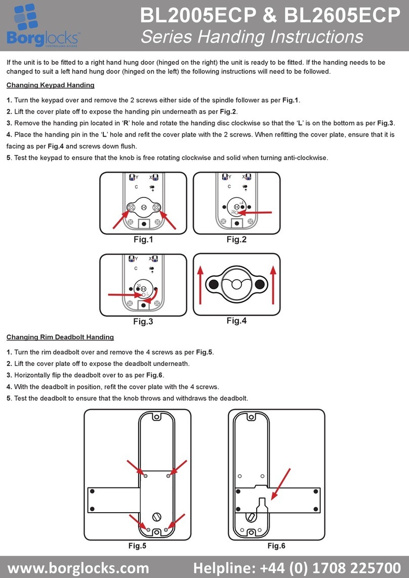
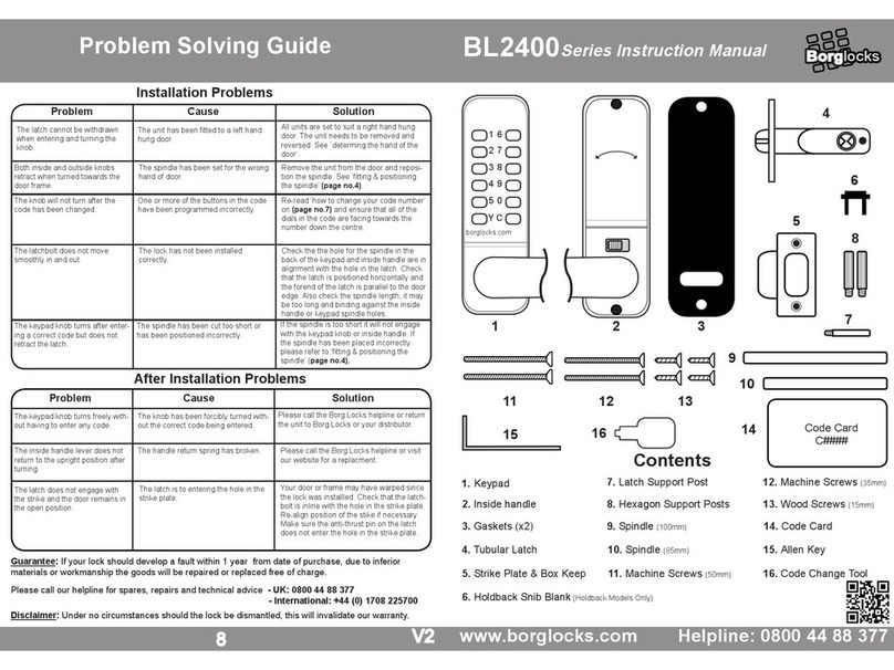
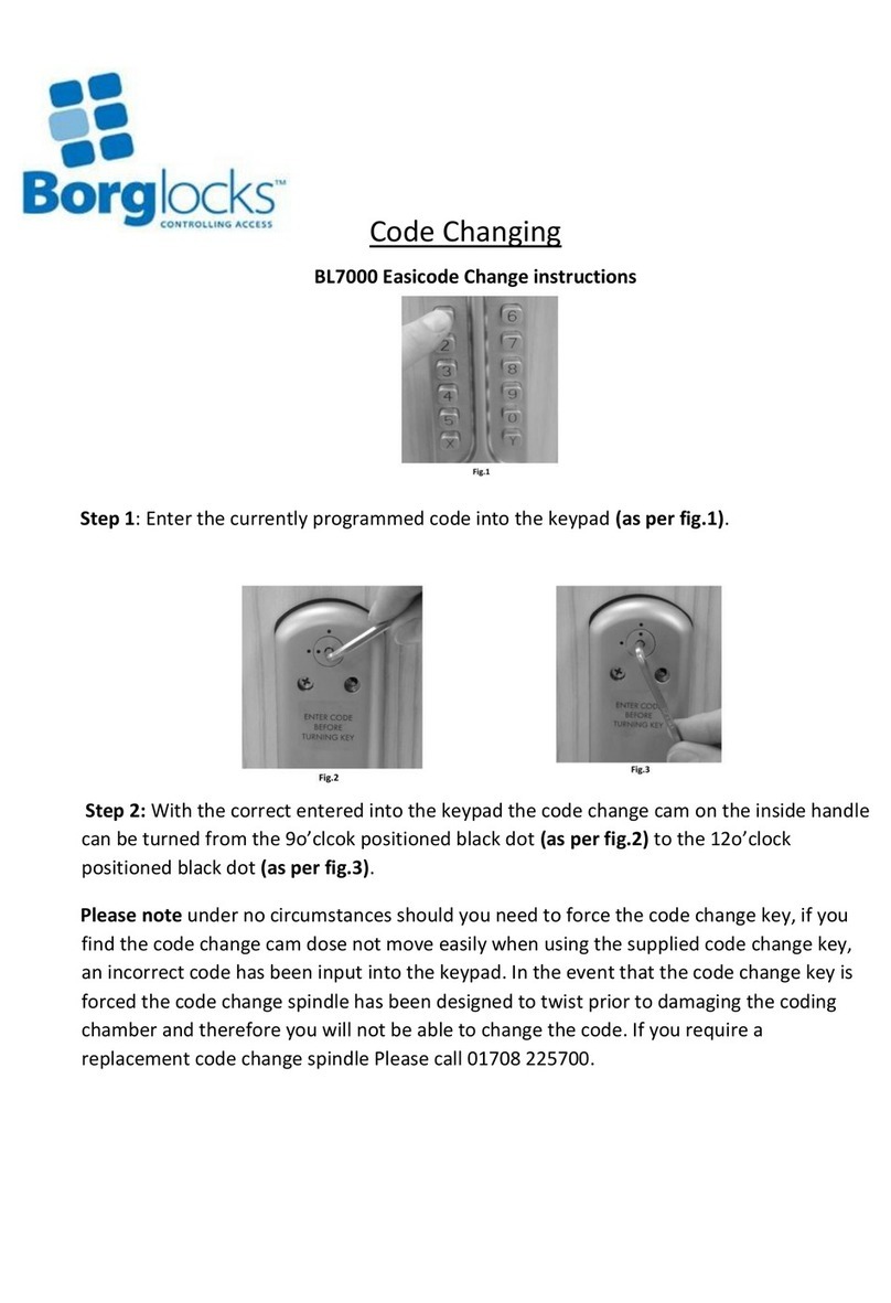
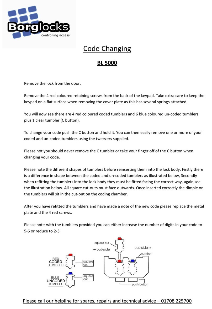
manuals.online logo
Brands
  1. Home
  2. •
  3. Brands
  4. •
  5. Borglocks
  6. •
  7. Lock
  8. •
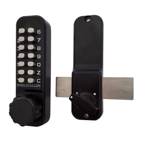
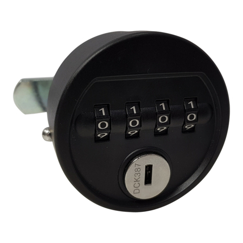
  9. Borglocks BL2605MG User manual

Borglocks BL2605MG User manual

1
BL2605MG
Installation Guide, Parts List & Maintenance
Instructions
Parts List:
Surface Lock Keep x 2
Neoprene Seals x 2
Factory Pre-set Code
Card
Wood Screws x 8
Hexagonal shaft x 2
2 3/8” (60mm)
Tweezers x 1
Spare Tumblers
2 x coded
2 x blank
Wood Screws x 4
Mortised Lock Keep
Fixing Bolts (6 supplied)
Use only 2 depending on gate thickness. See table 4A
80 mm x 2 (3 1/8”)
70 mm x 1 (2 ¾”)
60 mm x 1 (2 3/8”)
50 mm x 1 (2”)
40 mm x 1 (1 ½”)
Spindle/ Key Stock x 3
135 mm x 1 (5 5/16”)
160 mm x 1 (6 5/16”)
135mm x 1 (5 5/16”)
Keypad
Inside Lock Body
Morticed Lock Keep
2
Before commencing installation, check that all parts are working correctly. Press the code into the lock,
as per the code card provided and then turn the knob it should turn easily under spring pressure. If you intend
to change the code, this should be done before installing the lock, see “How to Change your Code”.
How to Change Your Code: The C button must be held down during recoding process
Before installing the lock, or Remove the lock from the door
1. Take EXTRA care to keep the keypad on a flat surface when you are removing the cover plate, as there
are many small components inside under spring pressure.
2. Carefully remove the 2 retaining screws from the back of the keypad that hold the code chamber
cover plate in place. The screws are next to the numbers in the plate that has 14 holes in it.
3. You will now see that there are 5 red coloured coded tumblers and 8 blue coloured non-coded
tumblers plus 1 clear tumbler (’C’ button).
4. To change your code, push the ‘C’ button down and hold it. You can easily remove one or more of your
coded and non-coded tumblers using the tweezers supplied.
Remember, the red tumblers represent coded digits and the blue tumblers represent non coded digits.
NOTE: NEVER remove the ‘C’ tumbler.
Please take care to notice the difference in the tumbler shapes before reinserting them into the lock body.
Firstly, there is a difference in shape between the coded and non-coded tumblers, illustrated below. Secondly,
when fitting the tumblers into the lock body, they must be fitted facing the correct direction, again see
illustration below. All square cut outs must face outwards.
5. After you have refitted the tumblers and make note of your new code, please replace the metal plate
with the 2 screws.
Table 1A:
Please note: With the spare tumblers provided, you can either increase the number of digits in your code to 6-7
or reduce your code to 3-4. Numbers may only be part of the code once – you cannot use any number more
than once. (i.e. 1234 would be acceptable and 1224 would not be acceptable)
Gate Thickness Table: Table 2A
Borg Lock Table
Hexagonal Shaft Length Length of
Screws Installed
Minimum
Gate
Thickness
Maximum
Gate
Thickness
Short
1 ½” & 2"
1 ¼”
1 7/8"
1” (24mm) length supplied on lock
2" & 2 3/8"
1 1/2"
2 3/8"
2 3/8" & 2 3/4"
2"
2 5/8"
2 3/4" & 3 1/8"
2 3/8"
3"
3 1/8” & 3 1/8”
2 5/8”
3 1/8”
Long
1 ½” & 2"
2 1/2"
3 1/4"
2 3/8” (60mm) length supplied additionally
2" & 2 3/8"
3"
3 ½ "
2 3/8" & 2 3/4"
3 3/8"
4 ¼ ”
2 3/4" & 3"
3 3/4"
4 ¼ "
3 1/8" & 3 1/8”
4 1/4"
4 ¼ "
Note: Cut Keystock/Spindle 1 5/8" longer than the thickness of your gate or door.
Square Cut-out
Buttons
Outward
s Outward
s
Square Cut-out
Square
Cut-out
Red Coded Tumbler
Blue Non-Coded
Tumbler
Square
Cut-out
3
FLUSH ON THE OUTSIDE
INSTALLED IN CENTER OF OPENING
FLUSH ON THE INSIDE
Determining your Gate Handing (Table 3A) Right Hand installation shown below
Changing the Handing of Lock (Table 4A)
Installation Exploded View (Table 5A)
4
Snug Cottage Hardware
Marysville Michigan, USA and London, Ontario, Canada
1-800-637-5427
www.snugcottagehardware.com
Installation instructions:
1. Using Diagram 3 determine which hand (left or right) lock you require for your specific application.
2. Using table 2A determine the length of the machine screws, hexagonal shaft and key stock spindle configuration
required for your gate or door thickness. This lock comes equipped to fit up to a 4 1/4” thick gate or door.
3. Using a hack saw cut the key stock spindle 1 5/8” longer than the thickness of your gate or door. Be careful the key
stock spindle is not cut too long as pinching it in between the two parts of the lock body when you install the
machine screws during assembly will possibly prevent free movement of the lock parts.
a. for gates or doors under the 1 ¾” thickness use the flat key stock spindle and cut to the appropriate length for
your application.
b. for gates or doors between 1 ¾ ” and 3” thick use the key stock spindle that is 135mm and has the heavier
“round” part in the middle – the heavier stock will resist twisting better at the longer lengths.
c. For gates or doors between 2 ¾” and 4 ¼” thick use the key stock spindle that is 160mm and has the heavier
“round” part in the middle – the heavier stock will resist twisting better at the longer lengths.
Note: Please take care in cutting the Keystock/Spindles that you cut the correct amount off each end. The Keystock/Spindle
seats into the back part of each half of the lock a different depth so you need to account for this when using the
Keystock/Spindles that are round in the middle – you will need to cut a little from both ends.
4. Using the supplied drilling template locate where the holes will be drilled in your gate or door by marking the
centres. NOTE: The horizontal placement of the lock does not have to match the “edge of door” reference on the
drilling template. As the latching bolt moves a full 1” in its action. If using in the mortised position for instance, it
may be advantageous to move the lock position backwards or forwards depending on your specific installation.
Please pay special attention to this step to ensure best results.
5. Once you have determined the locks most suitable position, mark the 3 hole centers for drilling, using the
appropriate sized bits. The template indicates 10mm (3/8”) and 13mm (½”) holes. Place a block on the opposite
side of the door or gate too minimize tear out while drilling.
6. If you haven’t already changed the code or the handing, but wish to change the code or the handing, Please
refer to “How to Change Your Code” and “How to Change the Handing (Table 4A)” and do so now.
7. Add the black rubber lock base gaskets to each of the lock pieces at this time.
8. After reviewing the exploded view Table 5A - Carefully affix the lock to the door or gate using the appropriate sized
machine screws as determined in step 2. Be sure to install your key stock spindle at this time. NOTE: take great care
when starting the threads in the hexagonal shaft not to cross thread them. The threads are very fine- it is easy to
make a mistake. Tighten gently, do not overtighten.
9. Now the lock position is set you can install surface lock keeps for flush mount applications, or one surface lock keep
and one mortise lock keep for mortised installations. Both have elongated receiver slots to allow for some post
movement and settling.
10. Test the lock for accurate operation once complete
Maintenance Instructions
Monthly:
Clean the surface of the lock with a silicon based lubricant, remove any excess with a soft cloth. Do NOT use an oil based spray like
WD40 as this will attract dirt and debris.
Annually:
Remove the lock from the door.
Spray the inside of the lock thoroughly with a silicon based lubricant, through the tumbler holes at the back of the lock.
Spray all the fixing accessories and the latch with a silicon based lubricant.
Push each of the buttons and rotate the knob several times to ensure that the lock is working smoothly and the lubricant has
penetrated the lock appropriately. These procedures can be carried out as needed when lock is sticky or code is accepted
intermittently.
If you experience any problems when installing this lock, or changing the code please contact:

Other Borglocks Lock manuals

Borglocks BL2605MG Configuration guide

Borglocks

Borglocks BL2605MG Configuration guide

Borglocks BL 5000 User manual

Borglocks

Borglocks BL 5000 User manual

Borglocks BL2400 Series User manual

Borglocks

Borglocks BL2400 Series User manual

Borglocks BL7000 Easicode User manual

Borglocks

Borglocks BL7000 Easicode User manual

Borglocks BL4409 User manual

Borglocks

Borglocks BL4409 User manual

Borglocks BL2005ECP Series User manual

Borglocks

Borglocks BL2005ECP Series User manual

Borglocks BL2005 Configuration guide

Borglocks

Borglocks BL2005 Configuration guide

Borglocks BL 2605 MG Pro Configuration guide

Borglocks

Borglocks BL 2605 MG Pro Configuration guide

Borglocks BL2701 Quick guide

Borglocks

Borglocks BL2701 Quick guide

Borglocks BL2615MG Configuration guide

Borglocks

Borglocks BL2615MG Configuration guide

Borglocks BL3030ECP User manual

Borglocks

Borglocks BL3030ECP User manual

Borglocks BL2615MG Configuration guide

Borglocks

Borglocks BL2615MG Configuration guide

Popular Lock manuals by other brands

Kwikset 275 Installation and user guide

Kwikset

Kwikset 275 Installation and user guide

Kwikset 264 Installation and user guide

Kwikset

Kwikset 264 Installation and user guide

COMPX MFW 29138 Dimensional drawing

COMPX

COMPX MFW 29138 Dimensional drawing

CAME FROG series instructions

CAME

CAME FROG series instructions

Stock Loks C8719 instruction sheet

Stock Loks

Stock Loks C8719 instruction sheet

COMPX OU-4265-NA Dimensional drawing

COMPX

COMPX OU-4265-NA Dimensional drawing

DOM ENIQ Guardian manual

DOM

DOM ENIQ Guardian manual

Pilz PSEN sl restart interlock operating manual

Pilz

Pilz PSEN sl restart interlock operating manual

StarTech.com LTULOCK4D quick start guide

StarTech.com

StarTech.com LTULOCK4D quick start guide

Mottura 87 Series instructions

Mottura

Mottura 87 Series instructions

SDC 280 series Installation instructions and template

SDC

SDC 280 series Installation instructions and template

Baling H31 user manual

Baling

Baling H31 user manual

SG 6128 A Series installation instructions

SG

SG 6128 A Series installation instructions

Hasco Z1790 Series manual

Hasco

Hasco Z1790 Series manual

Stock Loks C8765 instruction sheet

Stock Loks

Stock Loks C8765 instruction sheet

CISA 17352 installation instructions

CISA

CISA 17352 installation instructions

Siemens CLKP installation instructions

Siemens

Siemens CLKP installation instructions

TimePilot CrossOver X45 Installation

TimePilot

TimePilot CrossOver X45 Installation

manuals.online logo
manuals.online logoBrands
  • About & Mission
  • Contact us
  • Privacy Policy
  • Terms and Conditions

Copyright 2025 Manuals.Online. All Rights Reserved.