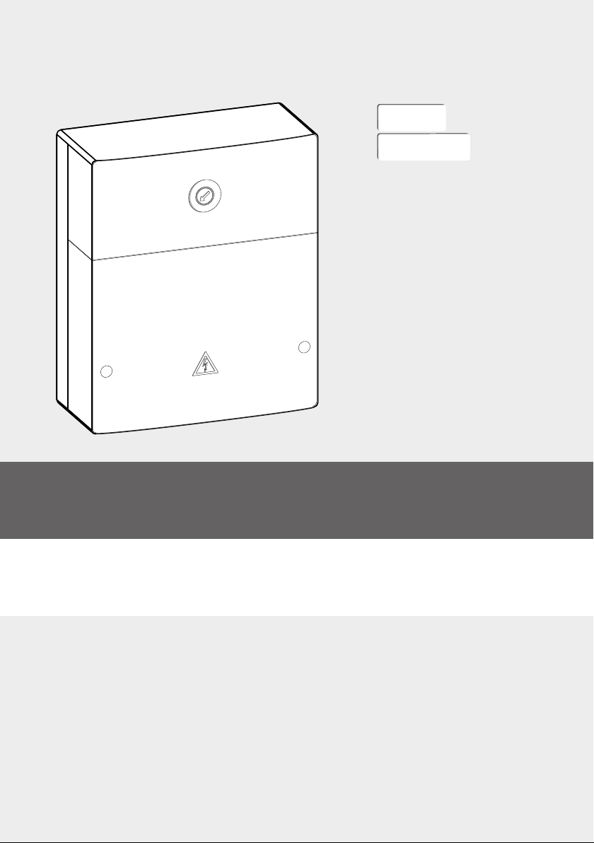
6 720 812 220 (2014/06)MP100
Installation
| 9
2.3 Cleaning and care
▶ If required, wipe the enclosure with a damp cloth. Never
use chemically aggressive or acidic cleaning agents.
2.4 Supplementary accessories
Forpreciseinformationregardingsuitable accessories, referto
the catalogue.
• For mixed swimming pool circuit:
– Mixer motor; connection to VC1
–
Swimmingpool temperaturesensor; connectionto TC1.
Installation of supplementary accessories
▶ Fit accessories according to legal requirements and the
installation instructions provided.
3 Installation
3.1 Installation
▶ Install the module on a wall (Fig. 3toFig. 5, page 78)or
on a mounting rail (Fig. 6, page 79).
▶ When removing the module from the mounting rail, refer to
Fig. 7 on page 79.
▶ Install the swimming pool temperature sensor TC1
(Fig. 1 [3], page 77) in a suitable place (Fig. 16,
page 83).
3.2 Electrical connection
▶ Observe current regulations applicable to power
connections, and use at least cable type H05 VV-…
3.2.1 Connecting the BUS connection and temperature
sensor (extra-low voltage side)
▶ If the conductor cross-sections are different, use the
junction box to connect the BUS nodes.
▶ Connect BUS nodes [B] via junction box [A] in star
(Fig. 12, page 81) or via BUS nodes with 2 BUS
connections in series (Fig. 16, page 83).
Maximum total length of BUS connections:
• 100 m at 0.50 mm2conductor cross-section
• 300 m at 1.50 mm2conductor cross-section
▶ Alllowvoltage leads mustbe routed separatelyfromcables
carrying mains voltage to avoid inductive interference
(minimum separation 100 mm).
▶ In the case of external inductive interferences (e.g. from
PV systems), use shielded cables (e.g. LIYCY) and earth
the shield on one side. The shield should be connected to
the building's earthing system, e.g. to a free earth
conductor terminal or water pipe, and not to the earth
connecting terminal in the module.
When sensor leads are extended, apply the following lead
cross-sections:
• Up to 20 m with 0.75 mm2to 1.50 mm2conductor cross-
section
• 20 m up to 100 m with 1.50 mm2conductor cross-section
▶ Route cables through the grommets provided and connect
them as shown in the connection diagrams.
3.2.2 Connecting the power supply, pump and mixing
valve (mains voltage side)
▶ Only use cable of comparable quality.
▶ Ensure correct polarity on the power supply.
Do not use standard plugs on fly leads for power supply.
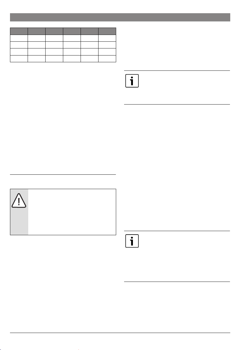
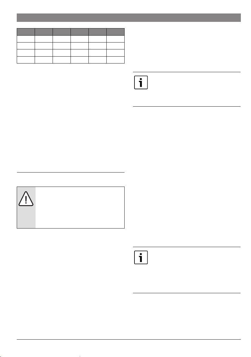
°C °C °C
20 14772 44 5730 68 2488
26 11500 50 4608 74 2053
32 9043 56 3723 80 1704
38 7174 62 3032 86 1421
Table 3 Pressure drop values of the connected swimming
pool temperature sensor
DANGER: Risk of electric shock!
▶ Before installing this product: completely
disconnect heat appliances and all other
BUS nodes from the mains voltage.
▶ Before commissioning: fit the cover
(Fig. 14, page 81).
If the maximum total length of the BUS
connections between all BUS nodes is
exceeded, or if the BUS system is realised as a
ring structure, the system cannot be
commissioned.
The assignment of the electrical connections
depends on the system installed. The
description shown in Fig. 8 to Fig. 11, from
page 79onwards,suggestsa possibleprocess
for assigning the electrical connections. Some
ofthesteps are notshownin black. This makes
it easier to see which steps belong together.