Detectores de metales y otros materiales digitales GMS120 bosch manual ingles www.viaindustrial.com
Detectores de metales y otros materiales digitales GMS120 bosch manual ingles www.viaindustrial.com
12
|
English
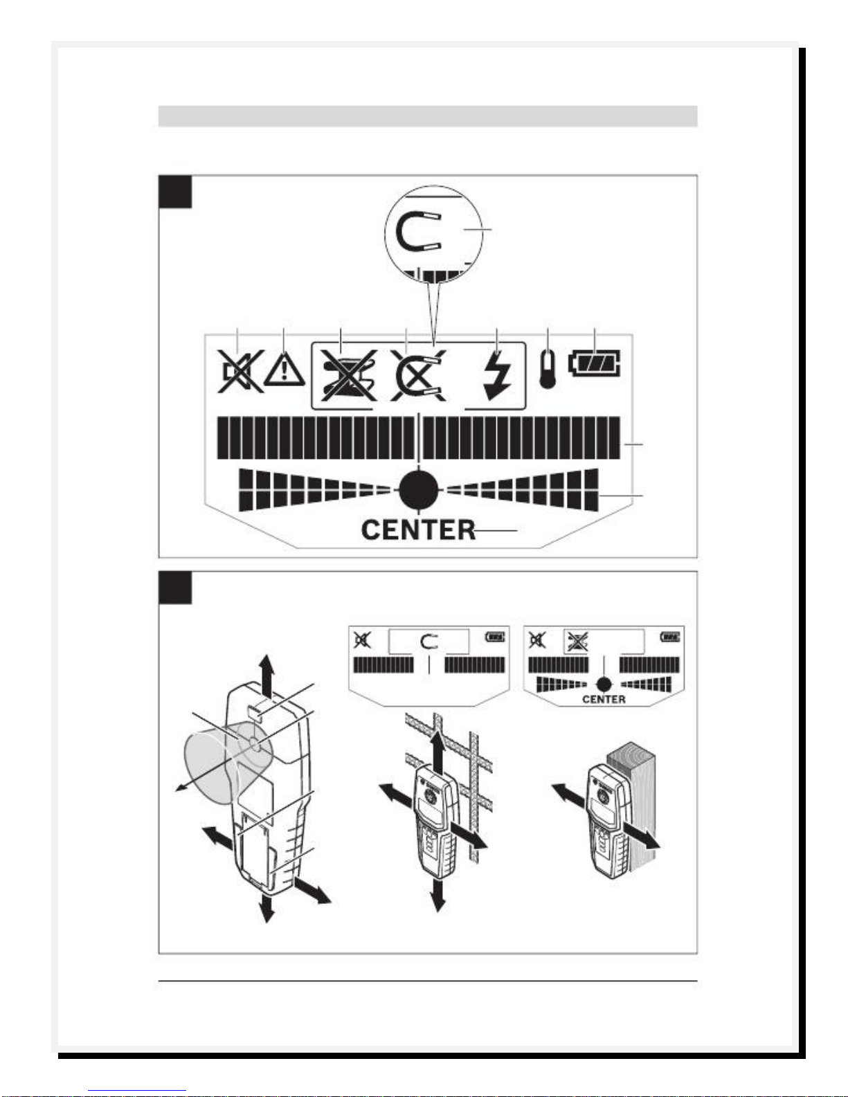
Method
of
Operation
(see
figures
A–B)
Themeasuring toolchecks thebase material of sensor area
12
in measurement direction
A
to themax.detectiondepth
(see “TechnicalData”).Objects aredetected that differfrom
thematerialof thewall.
Always movethemeasuringtoolin astraightlineoverthesur-
faceapplyingslightpressure, withoutliftingit off or changing
thepressure.Duringmeasurement,thecontactpads
11
must
always havecontact to thesurface.
Measuring
Procedure
Position themeasuring tool on/against the surface being
detected,andmoveit in direction
B
.Whenthemeasuringtool
comes closer to an object,theamplitudein measuringindica-
tor
i
increases andring
1
lights up yellow;whenit is moved
awayfromtheobject,theamplitudedecreases.Measuring
indicator
i
indicates themaximalamplitudeabove thecentre
of theobject;ring
1
lights up redandan audiosignal sounds.
Forsmallordeeplyembeddedobjects,ring
1
cancontinueto
lightup yellow,whilethereis no audio signal.
Wide
objects
are
not
indicated
by
the
illuminated
ring
or
the
audio
signal
throughout
their
complete
width.
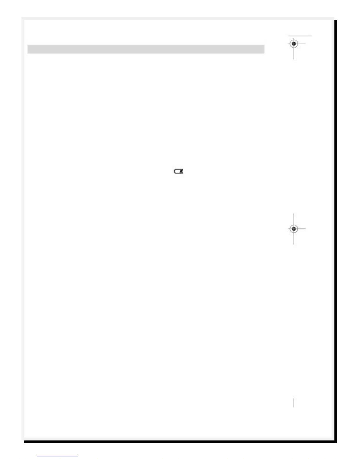
To localise theobjectmoreprecisely, move themeasuring
tool repeatedly (3x) back and forthover theobject.Thefine
scale
j
is automatically activated in all operating modes.Fine
scale
j
indicates afull amplitudewhentheobjectis belowthe
centreof thesensor or whenthemaximumamplitude of
measuring indicator
i
is reached. In theoperating modes
“Drywall”
and
“Metal”
,theindication
“CENTER”
k
lights up
additionally.
Widerobjects in the base materialaredetected through a
continuous, high amplitudeof measuring indicators
i
and
j
.
Ring
1
lights up yellow.Thedurationof the high amplitude
corresponds approximatelywith theobjectwidth.
When very small or deeplyembeddedobjects arebeing
sought andmeasuring indicator
i
reacts onlyslightly,move
themeasuring toolrepeatedlyovertheobjectin horizontal
and vertical direction.Pay attention to the amplitude of fine
scale
j
,and whenin operating mode
“Drywall”
and
“Metal”
,
additionallyto the
“CENTER
”
k
indication,whichwillthenal-
lowforprecise detection.
Before
drilling,
sawing
or
routing
into
a
wall,
protect
yourself
against
hazards
by
using
other
information
sources.
As themeasuring results canbe influenced
throughambientconditionsor thewallmaterial,theremay
be ahazardeventhough theindicatordoes notindicatean
objectin thesensorrange(noaudiosignalor beepandand
theilluminated ring
1
litgreen).
Operating
Modes
Thebest measuring results areachievedthroughselectionof
theoperating modes. Themaximal detectiondepth formetal
objects is achieved in theoperating mode
“Metal”
.Themax-
imal detection depth for“live”conductors is achieved in the
operating mode
“Power
cable”
.Theselected operating
modecanbe recognizedat anytimeviathegreenilluminated
operating-modeindication
4
.
Drywall
Theoperatingmode
“Drywall”
is suitablefordetectingwood
or metal objects in drywalls.
Press button
10
to activatetheoperating mode
“Drywall”
.
Theoperating-modeindication
4
abovebutton
10
lights up
green.As soonas themeasuringtoolis positionedagainstthe
base materialto be detected, ring
1
lights up greenand sig-
nals operational readiness.
Intheoperatingmode
“Drywall”
allobjecttypesaredetected
and indicated:
–
Non-metal,e.g. awood beam
–
Magnetic, e.g.reinforcing steel
–
Non-magnetic,butmetal,e.g.copperpipe
“Live”,e.g.a“live”conductor
Notes:
In theoperatingmode
“Drywall”
,otherobjects,apart
from wood andmetalobjects and “live”conductors arealso
detected,such as plastictubingfilled with water.For such
objects,theindication
c
fornon-metalobjects is indicated in
display
3
.
Nails andscrews in thebase material maycause awooden
beam to be indicated as ametalobjecton thedisplay.
When display
3
indicates acontinuouslyhigh amplitude of
measuring indicator
i
and finescale
j
,restart themeasuring
procedure againby positioning themeasuring tool at adiffer-
ent locationon thebase material.
When theilluminatedring
1
does notsignal operational read-
iness whenpositioning themeasuring tool on thebase mate-
rialbeingdetected,themeasuring toolcannot properly de-
tectthebase material.
–
Pressandholdbutton
10
untiltheilluminatedringlightsup
green.
–
Whenstartinganew measuringprocedureafterwardsand
positioning themeasuring tool onto adifferentwallor sur-
face,youmust brieflypress button
10
.
–
In rarecases,themeasuringtoolmaynotbe ableto detect
thebasematerialbecausethesidewith thesensorarea
12
and the typeplate
13
is soiled or dirty.Clean themeasur-
ingtoolwith adry,softclothandrestartthemeasuringpro-
cedure.
Metal
Theoperatingmode
“Metal”
is suitablefordetectingmagnet-
ic and non-magneticobjectsindependentof thewallmaterial.
Press button
9
to activatetheoperatingmode
“Metal”
.Theil-
luminatedring
1
andindication
4
above button
9
light up
green.
When thedetectedmetalobject is of magneticmetal(e.g.
iron),thesymbol
e
is indicatedon display
3
.For non-magnet-
ic metals,thesymbol
d
is indicated.In orderto differentiate
between metaltypes, themeasuring tool mustbe positioned
abovethedetectedmetal object (ring
1
is litred).
Note:
Forreinforcementsteelmeshandsteelintheexamined
base material,an amplitude is indicatedoverthecomplete
surface of measuring indicator
i
.For reinforcementsteel
mesh,it is typicalthatthesymbol
e
formagneticmetalis indi-
catedon thedisplay directlyabovetheironrods, whereasbe-
tweentheironrods,thesymbol
d
fornon-magneticmetalwill
appear.