manuals.online logo
Brands
  1. Home
  2. •
  3. Brands
  4. •
  5. Bosch
  6. •
  7. Receiver
  8. •
  9. Bosch ISW-EN4216R User manual

Bosch ISW-EN4216R User manual

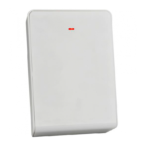
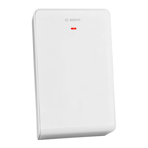
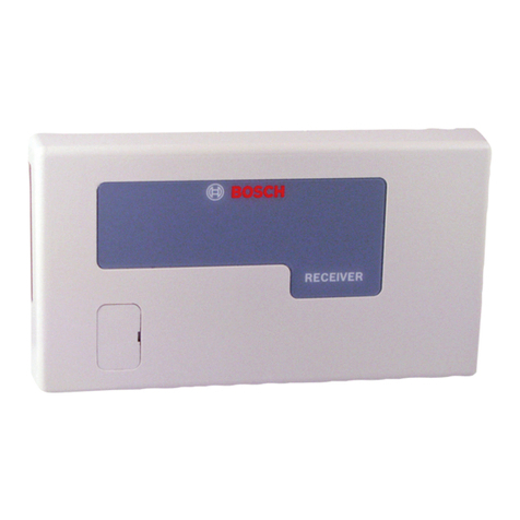
ISW-EN4216R Installation Guide LCD Receiver
Overview
The ISW-EN4216R LCD Receiver allows you to add up to 16
transmitters to any application. With diversity reception and
advanced signal processing, the ISW-EN4216R is designed to
minimize dead spots in transmission areas.
The ISW-EN4216R also provides six Form C relay outputs and a
relay fault output.
Figure 1: Front Panel Components
1 2 3
4
1 - Status LEDs (OUTPUT, ARMED, POWER)
2 - LCD Display
3 - Function buttons
4 - Access door
Table 1: Front Panel Components
LED/Button Description
OUTPUT LED Lights when any transmitter sends an alarm
signal.
ARMED LED Lights when the receiver is armed.
POWER LED Lights when the receiver has power.
LCD Display Shows status, event log, and programming
information.
UP button Press to scroll up through the display.
DOWN
button
Press to scroll down through the display.
BACK button Press to return the display to the previous
menu. If the display shows the Main Menu
options, press to return the receiver to normal
operation. When entering information, press to
return to the last entered character.
ENTER
button
Press to select the currently displayed menu
item. If the receiver is in normal operation,
press to enter the Main Menu.
Access door Remove the access door to see the Decode LED
or press the RESET button.
Decode LED Blinks when the receiver receives a recognizable
signal. This LED is visible only when you remove
the access door.
RESET
button
Press to clear the current status for all points
and to reset all outputs and LEDs. Pressing this
button records a Receiver Reset entry in the
event log, and resets the Supervision Window
timers. This button is visible only when you
remove the access door.
If no transmitter is selected, none of the status LEDs turn on. LEDs
turn on only to display the transmitter currently selected.
1.0 Open the Receiver Housing
Use a small flat-blade screwdriver to press either the top or bottom
housing release tabs and separate the cover from the base.
Figure 2: Open the Receiver Housing
1
2
1 - Top housing release tabs
2 - Bottom housing release tab
2.0 Connect the Power Cabling
Connect power and input/output cabling to the receiverís terminals.
Refer to Figure 3 for the location of each terminal, and Table 2
on page 2 for a description of each terminal.
In order to program the receiver, you must connect the power
cabling between the power source and the receiver.
The LCD Display shows the installed firmware revision, and then
shows the READY message.
Figure 3: Receiver Components
1 - LCD display
2 - UP button
3 - DOWN button
4 - BACK button
5 - ENTER button
6 - Arm Input terminal
7 - Reset Input terminal
8 - Tamper Output terminal
9 - Jam Output terminal
10 - Output terminals
11 - RESET button
12 - Decode LED
13 - Frequency Band pins
14 - GND terminal
15 - Power terminal
2 | F01U126806-01 | 4/09 ISW-EN4216R Installation Guide ©2009 Bosch Security Systems, Inc.
Table 2: Receiver Terminals
Terminal Description
Power/GND Connect the power cabling from the power
source to the Power and GND terminals on the
receiver.
The power source should be between 11 and 14
VDC, and must be unswitched, uninterrupted,
and regulated.
Arm Input This input controls event logging for points set to
LOG ARMED. If the Arm Input terminal is not
connected, events from points set to LOG
ARMED are not logged.
IMPORTANT: A low at the Arm Input terminal
enables event logging for points set to LOG
ARMED, but does not disarm the receiver.
Tamper
Output
This normally-open (N/O) output reports receiver
case tamper conditions to an external device.
Jam Output This normally-closed (N/C) output opens when
noise thresholds on all transmission channels
remain above a predetermined value for more
than 20 sec.
Reset Input This input allows the installation of a remote
momentarily normally open (N/O) switch to clear
faults, unlatch outputs, and reset the receiver to
a normal state.
Outputs These open collector outputs provide 6 Form C
relay circuits. Refer to Figure 4 and Figure 5 for
cable connections.
Figure 4: Relay N/O Wiring
1 6
2
3
4
5
2
3
7
9
8
1 - Control panel
2 - VDC terminal
3 - GND terminal
4 - Zone 1 terminal
5 - Common terminal
6 - ISW-EN4216R
7 - N/C terminal
8 - Common terminal
9 - N/O terminal
Figure 5: Relay N/C Wiring
1 6
2
3
4
5
2
3
6
8
7
1 - Control panel
2 - VDC terminal
3 - GND terminal
4 - Zone 1 terminal
5 - Common terminal
6 - ISW-EN4216R
7 - N/C terminal
8 - Common terminal
9 - N/O terminal
3.0 Select the Frequency Band
1. Select the appropriate frequency band for your geographic
area. Refer to Figure 6.
2. Press the RESET button. Refer to Figure 3 on page 1.
Figure 6: Frequency Band Settings
NZ
AUS
1
NZ
AUS
3
NZ
AUS
2
1 - Australia (915 MHz to 928 MHz)
2 - New Zealand (921 MHz to 928 MHz)
3 - North America (902 MHz to 928 MHz) (default)
4.0 Program the Receiver
4.1 Main Menu
1. When the LCD Display shows the READY message, press the
ENTER button to enter the Main Menu.
The Main Menu consists of three submenus. Refer to Table 3
for an overview of the Main Menu.
To navigate through the menus and make selections, refer to
Table 1 on page 1 for descriptions of the UP, DOWN, ENTER,
and BACK buttons.
Table 3: Main Menu
Submenu Description
POINT STATUS Use this menu to check the current status of a
programmed point.
INSTALL &
SERVICE
Use this menu to program an output, change
the login password, check signal strength, set
up a point, delete a point, and register a
transmitter.
EVENT LOG Use this menu to review events that were
recorded in the event log.
2. From the Main Menu, press ENTER to select a submenu.
Refer to Sections 4.2 through 4.4 on pages 3 and 4 for
programming guidelines.
©2009 Bosch Security Systems, Inc. ISW-EN4216R Installation Guide 4/09 | F01U126806-01 | 3
4.2 INSTALL & SERVICE Submenu
1. From the Main Menu, press ENTER to select the INSTALL &
SERVICE submenu.
2. Enter the password.
A numeric password is required to access the
INSTALL & SERVICE submenu. The default password is 3446.
3. Press UP or DOWN to scroll through the menu options. Press
ENTER to select a menu option.
4.2.1 Program Output
1. From the INSTALL & SERVICE submenu, select
PROGRAM OUTPUT.
2. Scroll through the list of available outputs (01 ñ 06), and press
ENTER to select the desired output.
3. Scroll through the list of available options.
Refer to Table 4 for descriptions of the options.
4. Press ENTER to select an option.
The display shows the PGM DONE message to indicate that the
output is now programmed. To program another output, press
ENTER. To return to the INSTALL & SERVICE submenu, press
ENTER and then BACK.
Table 4: Program Output Options
Option Description
Toggle The output changes state each time the device
sends a new activation. At least 5 sec must pass
before the output can send a new activation.
To prevent output noise, set the inactive time
between 2.0 sec and 99.5 sec (increments of
0.5 sec). The default is 4.0 sec.
Momentary The output turns on for the programmed
duration, and then turns off regardless of the
device status.
Set the time that the output remains active
between 0.5 sec and 99.5 sec (increments of
0.5 sec). The default is 4.0 sec.
Follower The output follows the transmitterís alarm
status.
Latching The output turns on when activated and remains
on until the receiver is reset.
4.2.2 Change Password
1. From the INSTALL & SERVICE submenu, select
CHANGE PASSWORD.
2. Enter a new numeric password up to eight digits in length.
To select a blank space, press ENTER without selecting a digit.
3. When finished, press ENTER to complete the selection.
When the PASSWORD CHANGED message appears, press
ENTER to return to the INSTALL & SERVICE submenu.
4.2.3 Monitor Signal Strength
Use the signal strength option to measure signal strength and
troubleshoot installation problems.
1. From the INSTALL & SERVICE submenu, select
SIGNAL STRENGTH.
The LCD display shows Point 1 and its current signal quality
(GOOD, WEAK, or NO SIG).
2. Press UP or DOWN to scroll through the registered
transmitters.
3. Press ENTER again to view Level (LV) or Margin (MA).
- Level: Indicates the overall signal strength.
- Margin: Indicates the signal strength minus the
background noise.
4. To reset signal data, press UP or DOWN to exit and return to
the transmitter currently selected.
4.2.4 Setup Point
When programming points, ensure that you do not
map faults to the same output as alarms.
1. From the INSTALL & SERVICE submenu, select SETUP POINT.
2. Press UP or DOWN to scroll through the available points (1-16).
3. Press ENTER to select a point.
- TX REGISTRíD: This message appears if a transmitter is
currently registered to the selected point.
- TX NOT REGISTRíD: This message appears if no
transmitter is registered to the selected point.
4. Press ENTER to program the selected point.
5. Press UP or DOWN to scroll through the programming options.
Refer to Table 5 for descriptions of the options.
6. Press ENTER to select an option for the point being
programmed.
Selecting -- disables the selected option.
Table 5: Setup Point Options
Option Description
SPV TIME Set the supervision time limit between 1 min
and 99 hr to report missing transmitters.
Select 00 to disable supervision time. The
default is 60 min.
IMPORTANT: Disabling supervision time is not
recommended.
INACTIVE OUT Map the device to the Inactivity Fault output.
TAMPER OUT Map the device to the Tamper Fault output.
LOW BATT
OUT
Map the device to the Low Battery Fault
output.
ALARM OUT Map the transmitter to the Alarm output.
AC LOSS OUT Map the repeater to the AC Loss output.
LOG ALWAYS Select whether to log events for this device at
all times or only when armed.
IMPORTANT: The log armed option logs events
only when a low is applied at the Arm Input
terminal.
TEXT Enter up to eight characters of descriptive text
for the transmitter/repeater.
-Press UP or DOWN to scroll through the
available alphanumeric characters.
-Press ENTER to select a character and
advance to the next space.
-To select a blank space, press ENTER
without selecting a character.
IMPORTANT: If you do not use all eight
characters, you must enter blank spaces at the
end of the line.
7. After making the programming selections, press ENTER again to
complete the programming.
© 2009 Bosch Security Systems, Inc.
130 Perinton Parkway, Fairport, NY 14450-9199 USA
(800) 289-0096
F01U126806-01
Installation Guide
4/0
9
ISW-EN4216
R
Page 4 of
4
4.2.5 Register a Transmitter
fter you program a point on the receiver, you can register a
transmitter to that point.
1. From the INSTALL & SERVICE submenu, select
REGISTER XMITTER.
2. Press UP or DOWN to scroll through the available points.
3. Press ENTER to select and register a point.
4. When the RESET XMITTER message appears, press the Reset
button on the transmitter.
5. When the TX REGSTRíD message appears, press ENTER to
finish and move to the next point.
4.3 POINT STATUS Submenu
1. From the READY, ALARM, or FAULT message, press ENTER.
2. Press ENTER to select POINT STATUS.
3. Press UP or DOWN to scroll through the available points.
4. Press ENTER to select a point and view its status:
- A: Alarm (transmitter only)
- T: Tamper
- B: Low battery
- L: AC loss (repeater only)
- I: Inactive
If -- appears, the displayed condition was mapped to a
null output.
4.4 EVENT LOG Submenu
1. From the READY, ALARM, or FAULT message, press ENTER.
2. Press UP or DOWN to scroll to EVENT LOG.
3. Press ENTER.
4. Press UP or DOWN to scroll through the list of events.
When viewing transmitter events, press ENTER to see the
output to which the events are mapped.
If the event is mapped to a disabled output, no output shows.
5.0 Mount the Receiver
Mount the receiver in a location away from metal
objects, such as duct work, wire mesh screens, or
boxes. Metal objects reduce RF range.
1. Use the supplied screws and anchors to mount the receiver in a
location that is accessible for future maintenance.
2. Close the receiver housing.
6.0 Alarms and Faults
If a point goes into alarm, the LCD Display shows ALARM along with
the point number. If more than one point is in alarm, the LCD
display scrolls through each point.
If a fault condition occurs, the LCD Display shows FAULT only if no
points are in an alarm condition. Point numbers are not shown for
fault conditions.
Use the POINT STATUS or EVENT LOG menu options to see more
information about fault conditions.
7.0 Specifications
Dimensions
(H x W x D)
162 mm x 92 mm x 28 mm
(6.38 in. x 3.60 in. x 1.10 in.)
Power Requirement 11 to 14 VDC
Current
Consumption
~400 mA max with all six relays energized
Output Rating 1 A, 28 VDC, or 0.5 A, 30 VAC (resistive)
Output Types •6 on-board Form C relays for
connecting to any control panel or
for stand-alone wireless applications
(N/O or N/C)
•1 N/O receiver case tamper contact
closure
•1 N/C receiver jam input indication
Input Specifications < 0.5 V = low; >2.5 V = high
Receiver Type Frequency hopping spread spectrum
Operating
Frequencies
USA: 902 MHz to-928 MHz
Australia: 915 MHz to-925 MHz
New Zealand: 921 MHz to 928 MHz
Number of
Points/Transmitters
16
Number of Alarm
Outputs
6 Form C relay outputs
Event Log Capacity 50 events (first-in, first-out replacement)
Operating
Temperature
0°C to +60°C (+32°F to +140°F)
Relative Humidity Up to 90% (non-condensing)

Other Bosch Receiver manuals

Bosch RFRC-OPT User manual

Bosch

Bosch RFRC-OPT User manual

Bosch Coach smartPanel NAFTA 7 620 210 046 Technical manual

Bosch

Bosch Coach smartPanel NAFTA 7 620 210 046 Technical manual

Bosch Radion B810 User manual

Bosch

Bosch Radion B810 User manual

Bosch EN4216R User manual

Bosch

Bosch EN4216R User manual

Bosch LR 2 Professional User manual

Bosch

Bosch LR 2 Professional User manual

Bosch Radion B810 User manual

Bosch

Bosch Radion B810 User manual

Bosch LR 1 Professional User manual

Bosch

Bosch LR 1 Professional User manual

Bosch LE10 User manual

Bosch

Bosch LE10 User manual

Bosch RE005EV2 User manual

Bosch

Bosch RE005EV2 User manual

Bosch GML 10,8 V-LI User manual

Bosch

Bosch GML 10,8 V-LI User manual

Bosch FA400 User manual

Bosch

Bosch FA400 User manual

Bosch LR 1 Professional User manual

Bosch

Bosch LR 1 Professional User manual

Bosch RE005EV2 User manual

Bosch

Bosch RE005EV2 User manual

Bosch LR30 User manual

Bosch

Bosch LR30 User manual

Bosch RF3224 User manual

Bosch

Bosch RF3224 User manual

Bosch LTC 8561 Series User manual

Bosch

Bosch LTC 8561 Series User manual

Bosch WE800EV2 RF User manual

Bosch

Bosch WE800EV2 RF User manual

Bosch Professional GCT 30-42 User manual

Bosch

Bosch Professional GCT 30-42 User manual

Bosch LR 2 Professional User manual

Bosch

Bosch LR 2 Professional User manual

Bosch Radion B810 User manual

Bosch

Bosch Radion B810 User manual

Bosch LR 6 User manual

Bosch

Bosch LR 6 User manual

Bosch LE10 User manual

Bosch

Bosch LE10 User manual

Bosch BLE 130 Professional User manual

Bosch

Bosch BLE 130 Professional User manual

Bosch RFRC-OPT User manual

Bosch

Bosch RFRC-OPT User manual

Popular Receiver manuals by other brands

Megasat HD 935 Twin user manual

Megasat

Megasat HD 935 Twin user manual

Yamaha RX-V361 owner's manual

Yamaha

Yamaha RX-V361 owner's manual

Pioneer AVH-P7900DVD Service manual

Pioneer

Pioneer AVH-P7900DVD Service manual

Zonge GDP-32II manual

Zonge

Zonge GDP-32II manual

GAS GMV300BT instructions

GAS

GAS GMV300BT instructions

Kenwood KMM-106 instruction manual

Kenwood

Kenwood KMM-106 instruction manual

FUTABA R7208SB manual

FUTABA

FUTABA R7208SB manual

Wave Central AXRX-QDM User and Programming Guide

Wave Central

Wave Central AXRX-QDM User and Programming Guide

Fortec Star MERCURY user manual

Fortec Star

Fortec Star MERCURY user manual

JVC KW-ADV792J Service manual

JVC

JVC KW-ADV792J Service manual

Meccanica Fadini Birio 868 quick start guide

Meccanica Fadini

Meccanica Fadini Birio 868 quick start guide

TracVision A5 instructions

TracVision

TracVision A5 instructions

JVC RX-8040B Service manual

JVC

JVC RX-8040B Service manual

Cisco IPN330HD installation manual

Cisco

Cisco IPN330HD installation manual

Rittal SV 9677.900 Assembly instructions

Rittal

Rittal SV 9677.900 Assembly instructions

Exibel DABX30C instruction manual

Exibel

Exibel DABX30C instruction manual

HP 83447A User's and service guide

HP

HP 83447A User's and service guide

Audiovox XR9 - XM Radio Tuner user guide

Audiovox

Audiovox XR9 - XM Radio Tuner user guide

manuals.online logo
manuals.online logoBrands
  • About & Mission
  • Contact us
  • Privacy Policy
  • Terms and Conditions

Copyright 2025 Manuals.Online. All Rights Reserved.