Bosch e-GoKart PowerTrain Young Star User manual

e-GoKart Powertrain "Young Star"
Manual
2 13/03/2019

Content
ii/60 e-GoKart_Powertrain__Young_Star__Manual Bosch Motorsport
Content
1 Getting Started................................................................................................................................................................ 3
2 Introduction .................................................................................................................................................................... 4
2.1 Conditions of Use................................................................................................................................................................................................. 4
3 System.............................................................................................................................................................................. 8
3.1 System Description.............................................................................................................................................................................................. 8
3.2 System Architecture............................................................................................................................................................................................. 9
3.3 System Functions.................................................................................................................................................................................................. 10
3.4 System Integration............................................................................................................................................................................................... 13
3.5 System Performance ........................................................................................................................................................................................... 13
3.6 System Operation................................................................................................................................................................................................. 14
4 Component Description ................................................................................................................................................. 16
4.1 Vehicle Control Unit VCU MS 40.................................................................................................................................................................... 16
4.2 Energy Storages ES 5-2.4................................................................................................................................................................................... 16
4.3 Power Unit PU 5-10 ............................................................................................................................................................................................. 19
4.4 DC/DC Converter.................................................................................................................................................................................................. 22
4.5 Charger Energy Storage CH 5-1.2.................................................................................................................................................................. 23
4.6 Display Unit DDU 18............................................................................................................................................................................................ 29
5 Overall Integration Requirements of e-GoKart System Components into the Superior Vehicle Context............ 31
5.1 Electrical Integration............................................................................................................................................................................................ 31
5.2 Mechanical Integration ...................................................................................................................................................................................... 31
5.3 Component Integration Requirements........................................................................................................................................................ 32
6 Wiring Harness instruction / Build up chassis............................................................................................................. 41
6.1 Implement the Components............................................................................................................................................................................ 41
6.2 Vehicle Control Unit VCU MS 40.................................................................................................................................................................... 58
7 Troubleshooting.............................................................................................................................................................. 59

Getting Started | 1
Bosch Motorsport e-GoKart_Powertrain__Young_Star__Manual 3/60
1 Getting Started
Disclaimer
Due to continuous enhancements we reserve the rights to change illustrations, photos or
technical data within this manual. Please retain this manual for your records.
Before starting
Before starting your engine for the first time, install the complete software. Bosch Motor-
sport software is developed for Windows operation systems. Read the manual carefully
and follow the application hints step by step. Don’t hesitate to contact us. Contact data
can be found on the backside of this document.
CAUTION
Risk of injury if using the Powertrain e-GoKart inappropriately.
Use the Powertrain e-GoKart only as intended in this manual. Any maintenance or repair
must be performed by authorized and qualified personnel approved by Bosch Motorsport.
CAUTION
Risk of injury if using the Powertrain e-GoKart with uncertified com-
binations and accessories
Operation of the Powertrain e-GoKart is only certified with the combinations and ac-
cessories that are specified in this manual. The use of variant combinations, accessories
and other devices outside the scope of this manual is only permitted when they have
been determined to be compliant from a performance and safety standpoint by a repres-
entative from Bosch Motorsport.
NOTICE
For professionals only.
The Bosch Motorsport Powertrain e-GoKart was developed for use by professionals and
requires in depth knowledge of automobile technology and experience in motorsport. Us-
ing the system does not come without its risks.
It is the duty of the customer to use the system for motor racing purposes only and not
on public roads. We accept no responsibility for the reliability of the system on public
roads. In the event that the system is used on public roads, we shall not be held respons-
ible or liable for damages.
NOTICE
Drive-by-wire systems
For systems with drive-by-wire additional safety provisions apply. For details please refer
to the document „Safety Instructions for Drive-by-Wire Systems in Motorsport Applica-
tions“.

2 | Introduction
4/60 e-GoKart_Powertrain__Young_Star__Manual Bosch Motorsport
2 Introduction
This system specification is a technical documentation of the BOSCH MOTORSPORT 48 V
E-GoKart System. It describes the E-GoKart System architecture, system components, per-
formance and functions, as well as the integration and application of the system in E-
GoKarts.
Furthermore this document informs the CUSTOMER about the product concerning
– intended use,
– forbidden misuse,
– operation conditions,
– validation,
– requirements to the superior vehicle system,
– requirements to the CUSTOMER for correct and safe use,
– requirements for integration and application of the product in the superior vehicle
system,
– responsibilities.
List of terms used in this document
Term Explanation
CUSTOMER The CUSTOMER is the purchaser of the sys-
tem, described in this document. If the
CUSTOMER is not the vehicle manufacturer,
this party has to ensure, that the obliga-
tions of the vehicle manufacturer are real-
ized by the vehicle manufacturer. This aims
especially to the compliance with the bot-
tom up requirements.
BOSCH MOTORSPORT BOSCH Engineering GmbH as the manufac-
turer / supplier of BOSCH MOTORSPORT E-
GoKart System, described in this document.
2.1 Conditions of Use
2.1.1 Terms and Specifications for Product Liability
Please be especially aware of all conditions states in the following section.
Business relations concerning use of sample parts:
Conditions which have been agreed on for series parts do not apply for sample parts.
Warranty:
BOSCH MOTORSPORT will only warrant CUSTOMER samples to be free of production
faults. All other warranties expressed or implied are excluded unless otherwise required by
law. BOSCH MOTORSPORT warrants products to comply with deliverable requirements
and does not warrant the CUSTOMER calibration. Any claim for damages, in particular,
concerning consequential loss, is excluded as far as there is no legal liability. Warranty of
deliverables is limited to either full replacement of the part or repair. Warranties exceed-
ing contents of this document in terms of function, reliability or safety do not apply.

Introduction | 2
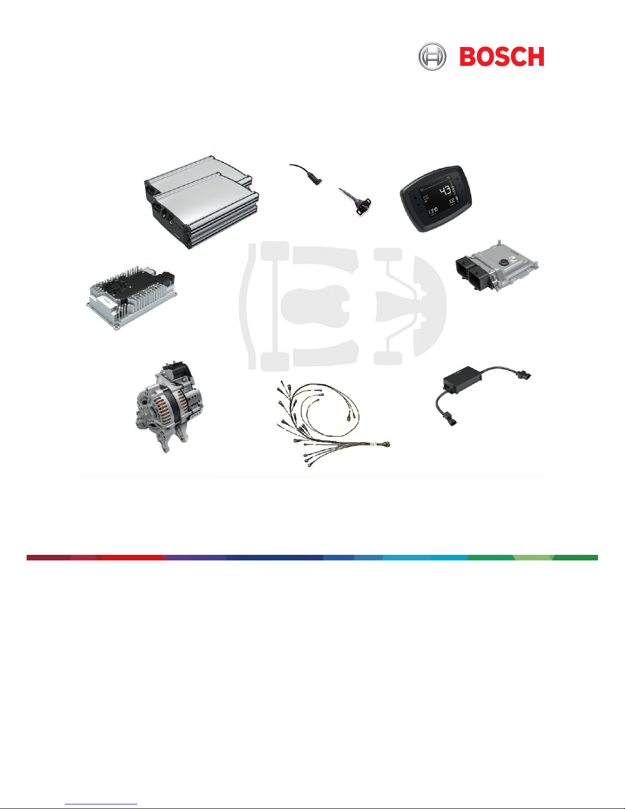
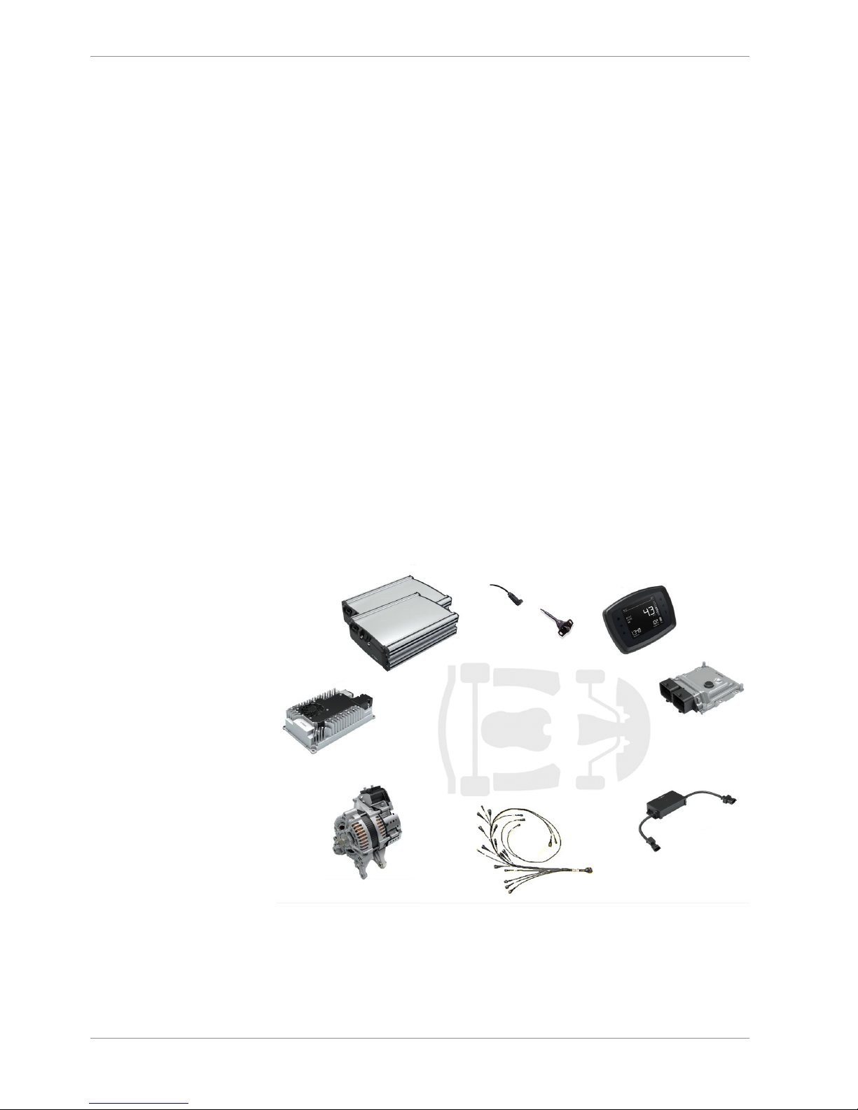
Bosch Motorsport e-GoKart_Powertrain__Young_Star__Manual 5/60
2.1.2 Safety and Warning Notes
To avoid the risk of an electric shock, which can lead to death or serious injury, any short
circuit of the interfaces (poles) of the Energy Storages ES 5-2.4, e.g. by tool drop, shall be
avoided.
2.1.3 Conditions for Transport and Storage
Storage of the product between shipment from BOSCH MOTORSPORT plant and mount-
ing/initial operation at the CUSTOMER shall be realized in defined transport packaging.
# Deliverables shall be handled with care.
If possible, all BOSCH MOTORSPORT e-GoKart System components are shipped as com-
plete units packed securely in appropriate transportation devices to protect the compon-
ents from damage or corrosion (protection against dust, moisture, precipitation, solar irra-
diation, etc.) that may result from usual transportation conditions.
# The CUSTOMER shall inform BOSCH MOTORSPORT if irregular / special transportation
conditions may occur having an impact on usual transportation devices applied.
# During storage of unpacked components at CUSTOMER site the CUSTOMER shall en-
sure that products are protected against damage or corrosion.
# Deliverables shall be stored for maximum 1 year.
# Deliverables shall only be transported or stored with an environment temperature
<80°C.
If above conditions are not fulfilled, the intended application is only allowed after inspec-
tion and agreement by BOSCH MOTORSPORT. Related expenses have to be compensated
by the CUSTOMER.
# Deliverables shall not be stored in humid/moist conditions (especially in case of oversea
transportation) and shall never be exposed to extreme heat or fire nor corrosive sub-
stances. This applies to installed and uninstalled units as well as packed and unpacked
units. If components are strongly subjected to water (e.g. due to transportation, applica-
tion of a cleaning process), a drying process shall be performed before storing those.
# Deliverables are not allowed to fall or be subjected to uncommon stresses (temperature,
acceleration, ultraviolet rays, etc.). In these circumstances further use of the deliverables is
not permitted.
# During storage, all external electrical connections from the application input/output in-
terfaces and the power connector shall be removed and connector inserts, where sup-
plied, fitted.
# During storage or transport of the unpacked BOSCH MOTORSPORT e-GoKart System
electrostatic charging and discharging of unpacked Energy Storages ES 5-2.4 shall be
avoided.
# There shall never be placed any heavy objects on unpacked deliverables (especially the
48 V Energy Storages ES 5-2.4) or the inter-connecting cables.
# The Power Unit 5-10 shall be transported or stored horizontally.
# Axial loads or shocks on the rotor shaft of the unpacked e-GoKart Drive unit are not
permitted. This may result in pre-damage of bearings. This applies also to operation.
# The Power Unit 5-10 is not allowed to fall or be subjected to uncommon stresses (tem-
perature, acceleration, ultraviolet rays, etc.). Under these circumstances, further use of the
e-GoKart Drive unit is not permitted.

2 | Introduction
6/60 e-GoKart_Powertrain__Young_Star__Manual Bosch Motorsport
# The product's operating safety is only ensured if the permissible conditions are met.
If a 48 V Energy Storage ES 5-2.4 is stored or not operated it can be stored for 6 months
with start-SOC of ≥30 % for each 48 V Energy Storage ES 5-2.4 without recharging. The
Energy Storages ES 5-2.4 are delivered with an initial SOC ≥25 %. A check of the SOC of
the delivered energy storages is recommended before storage. This applies also for 48 V
Energy Storages 5-2.4 installed in the vehicle.
# The CUSTOMER is responsible for the review and application of all applicable regula-
tions as well as industry standards for lifting deliverables.
# Do not modify or alter any component. In case, it is necessary to modify or alter com-
ponents (e.g. the Energy Storage 5-2.4), contact BOSCH MOTORSPORT in advance.
Energy Storages 5-2.4 have a low internal impedance and may provide damaging currents
if misconnected.
# Reverse polarity and operation with disconnected plug shall be avoided.
# The outer temperature of deliverables increases during operation causing temperature
radiation. If necessary, the CUSTOMER shall install protection for limiting the temperature
radiation. If necessary, the CUSTOMER shall install thermal insulation measures in order to
avoid damage of adjacent components.
2.1.4 Environmental Conditions
The BOSCH MOTORSPORT e-GoKart System is designed for an operation in typical
European climate zones with an ambient temperature of 5 to 35°C. Operation with re-
duced performance is possible for -8 to 40°C ambient temperature. Performance reduc-
tion depends on the application and vehicle design. Charging and recuperation is possible
for >5°C ambient temperature.
Inner temperatures of components might differ from ambient temperature due to installa-
tion position and operation history. The BOSCH MOTORSPORT e-GoKart System measures
the temperature of the 48 V Energy Storage ES 5-2.4 on cell level. If the cell temperature
exceeds defined limits (-8 to 58°C for driving and 5 to 44°C for charging), the BOSCH MO-
TORSPORT e-GoKart System autonomously prevents driving and charging and informs
the driver, see section System Screens [}14].
Illustration1: Temperature Range
The BOSCH MOTORSPORT e-GoKart System is designed for an environment with a relat-
ive humidity of 0 to 80%.
2.1.5 Maintenance and Repair
# The CUSTOMER shall ensure that electrical connection and electrical isolation of the
components are reliable over lifetime. It is recommended that during frequent service of
the vehicle the following checks are executed to ensure safe operation:

Introduction | 2
Bosch Motorsport e-GoKart_Powertrain__Young_Star__Manual 7/60
– Adequate and reliable electrical connection between charger housing and vehicle
chassis has to be ensured. No corrosion of the interface from charger housing to
chassis and multiple chassis parts, if applicable. This is to ensure the protective earth
connection from AC-plug to vehicle.
– Tightening torque of the termination bolts of the Power Unit PU 5-10, Energy Storage
ES 5-2.4, Charger Energy Storage CH 5-1.2 and 48 V star point interconnection - if ap-
plicable - have to be checked.
– AC cable from AC plug to Charger Energy Storage CH 5-1.2 has to be checked. If the
cable has any damages, it has to be replaced. It is not allowed to use a vehicle with
defect AC cable.
– All movable cables have to be checked, e.g. cables to the Power Unit PU 5-10, if the
Power Unit PU 5-10 is integrated in rear swinging fork.
– If the isolation is defect, the cable has to be exchanged or repaired.
# Service and repair or replacement of the product may only be performed by authorized
staff.
There are no user serviceable parts in the Energy Storage ES 5-2.4. Delivered lithium-ion
Energy Storages ES 5-2.4 are designed to be maintenance free, when during use recom-
mended operating and charging instructions are met.

3 | System
8/60 e-GoKart_Powertrain__Young_Star__Manual Bosch Motorsport
3 System
The e-GoKart System combines traditional karting and future-oriented technology. High
energy and power density of the air-cooled system components are ideal for small and
lightweight vehicles like e-GoKarts. With high torque, the e-GoKart System supports con-
vincing driving behavior and fun-to-drive. The e-GoKart System provides high power over
a wide range for maximum vehicle speed. By intelligent software, the e-GoKart System
gets the best out of the vehicle at any time and any driving profile, energy recuperation
included. The system is safe and reliable based on automotive qualified components and
a development approach according to automotive standards. The e-GoKart System is a
platform for easy scalability over different vehicle classes and types.
3.1 System Description
The BOSCH MOTORSPORT e-GoKart System perfectly harmonizes components for an
easy and fast electrification and a unique driving experience. Therefore several compon-
ents are connected in a system context to form a high performance system to meet the
needs of the CUSTOMER.
The following figure shows schematically the BOSCH MOTORSPORT e-GoKart System
components in a typical electric rental kart application: Power Unit PU 5-10, Energy Stor-
age ES 5-2.4 (48 V lithium-ion battery pack(s)), Vehicle Control Unit VCU MS 40, Charger
Energy Storage CH 5-1.2, DC/DC converter and Display Unit DDU 18. All these compon-
ents are combined and connected to the BOSCH MOTORSPORT e-GoKart System to
provide optimal performance for the CUSTOMER vehicle.
Illustration2: Overview of the BOSCH MOTORSPORT e-GoKart System components

System | 3
Bosch Motorsport e-GoKart_Powertrain__Young_Star__Manual 9/60
3.2 System Architecture
3.2.1 Voltage Level 12 V and 48 V Net
The traction net has a nominal voltage of 48 V.
There is an additional voltage net for power supply of the low-voltage components (e.g.
Vehicle Control Unit VCU MS 40, Display Unit DDU 18, auxiliary components) with a
voltage of 12 V.
12 V voltage range
Voltage Effect
-12 V Reverse polarity; damage of the system pos-
sible.
<6 V System cannot be activated.
During driving cycle, system will shut-off.
Driver has to turn the key (terminal 15) to
restart the system.
6 to 8 V System will remain active, but will not sup-
port driving torque.
System returns automatically to full func-
tionality when voltage is >8 V.
8 to 16 V Normal operating range.
>16 V Damage possible
48 V traction net voltage range
Voltage Effect
32.5 V System will shut-off for the current driving
cycle.
Driver has to turn the key (terminal 15) to
restart the system.
System should be charged.
32.5 to 42.25 V System will remain active, but will derate
driving torque.
42.25 to 52 V System returns automatically to full func-
tionality when voltage is >36 V.
52 to 54 V Normal operating range.
3.2.2 12 V Battery
The BOSCH MOTORSPORT e-GoKart System requires a 12 V battery for start-up. During
operation the 12 V battery is recharged by the BOSH MOTORSPORT e-GoKart System.
# If the BOSCH MOTORSPORT e-GoKart System is active the 12 V current consumption is
about 0.03 A (Power Unit PU 5-10 ≤ 5.0 mA, DC/DC converter ≤ 20 mA, Charger Energy
Storage CH 5-1.2 ≤ 5.0 mA). This shall be considered for the selection of a suitable 12 V
battery. It is recommended that the 12 V battery shall have a capacity of at least 6 Ah up
to 40 Ah nominal, depending on 12 V consumers / loads in the vehicle. A smaller capacity

3 | System
10/60 e-GoKart_Powertrain__Young_Star__Manual Bosch Motorsport
may be installed but requires calibration of a recharge timer to prevent deep discharge of
the 12 V battery during long-term storage. The 12 V battery is not in BOSCH MOTORS-
PORT scope of delivery.
NOTICE! It is not allowed to implement a different battery type as a lead battery.
3.3 System Functions
3.3.1 Start Up
Start-up time for the complete BOSCH MOTORSPORT e-GoKart System is below 2
seconds. Within that time the vehicle is ready to drive.
3.3.2 Driving
The BOSCH MOTORSPORT e-GoKart System provides three different drive mode with
positive (forward) torque. Available drive modes are GO, CRUISE, BOOST. These drive
modes differ in driving performance.
– GO mode implements a performance limitation in order to reach maximum range due
to energy saving.
– CRUISE mode implements driving characteristics balancing performance and energy
saving.
– BOOST mode implements driving characteristics for maximum performance of the
BOSCH MOTORSPORT e-GoKart System.
When switching the drive modes during driving, torque will be ramped up or down re-
spectively, so that no sudden torque variations may occur.
3.3.3 Speed Limiter
In order to make the driving experience for the driver as comfortable as possible the
BOSCH MOTORSPORT e-GoKart System implements a speed-limiting function that en-
ables a smooth transition towards top speed.
3.3.4 Offboard Charging
Charging the Energy Storage ES 5-2.4 with the Charger Energy Storage CH 5-1.2, as de-
scribed in Charger Energy Storage CH 5-1.2 [}23] is only possible with BOSCH MOTORS-
PORT Energy Storages ES 5-2.4.
3.3.5 Range Prediction
The BOSCH MOTORSPORT e-GoKart System calculates the remaining range possible to
drive taking into account the current driving conditions and previously measured energy
consumption (history). The predicted range depends on the energy consumption in selec-
ted drive mode and thus strongly on the driving behavior of the driver. As the predicted
range is an estimated value, there is no guarantee this range can be reached under all cir-
cumstances. The predicted range adapts to the currently selected drive mode. The history
can be reset by the user in the Display DDU 18 configuration menu.

System | 3
Bosch Motorsport e-GoKart_Powertrain__Young_Star__Manual 11/60
If the predicted range is lower than 5 km, the predicted range is not updated anymore un-
til the state of charge of the Energy Storages ES 5-2.4 reaches the lower limit. In this case
the predicted range is displayed with a blinking symbol marked with "<5",
3.3.6 Demand and Brake Signal Plausibilization
In case of implausible demand signals the BOSCH MOTORSPORT e-GoKart System will
prevent torque but remain active.
Brake signals are needed for system start. In case of loss of brake signals, driving is locked.
3.3.7 Derating
If the BOSCH MOTORSPORT e-GoKart System is not able to provide full output power, the
maximum power is automatically limited to an allowed level. This temporary limitation is
called derating and is generally caused by high temperature of the electric machine or any
of the available Energy Storages ES 5-2.4. Derating ensures component protection without
having a sudden loss of operation. The power limitation is dynamically based on system
conditions and is reversible, i.e. the system returns to full power as soon as limitation is
not necessary anymore. Active derating is indicated to the driver via a segmented power
bar in the right hand side of the Display DDU 18. If derating is active, segments are faded
out corresponding to the current power limitation.
Illustration3: Indication of derating: Limited drive power
Derating can also affect recuperation power and thus electrical braking performance.
Illustration4: Indication of derating: Limited recuperation

3 | System
12/60 e-GoKart_Powertrain__Young_Star__Manual Bosch Motorsport
3.3.8 Malfunction Indication
The Display DDU 18 is capable to indicate critical faults of the BOSCH MOTORSPORT e-
GoKart System to the driver via a dedicated malfunction indication lamp (MIL) implemen-
ted as telltale in the Display DDU 18, see blue marked lamp in the following figure.
Illustration5: Malfunction Indication Lamp
Additionally some internal faults of the BOSCH MOTORSPORT e-GoKart System, e.g. faults
in the torque path, will lead to very limited operation with a minimum allowable speed of
5 km/h and low torque. This state is called limp-home operation and enables the driver to
bring the vehicle into a safe parking position.
3.3.9 Software Updates (Flashing)
Updating the BOSCH MOTORSPORT e-GoKart System software (flashing) is possible for all
system components via one single system interface with a defined tester-interface infra-
structure.
Software updates will be provided by BOSCH MOTORSPORT if necessary.
# It is not allowed to update the software of the BOSCH MOTORSPORT e-GoKart System
by the CUSTOMER or any other third party without explicit authorization by BOSCH MO-
TORSPORT.
3.3.10 Deep Discharge Protection
Operation of the BOSCH MOTORSPORT e-GoKart System is only possible if the Energy
Storages ES 5-2.4 are charged frequently. Under normal conditions a software functional-
ity of the BOSCH MOTORSPORT e-GoKart System operates all Energy Storages ES 5-2.4 in
valid operational limits so that no Energy Storage ES 5-2.4 will run in deep discharge state.
Once this limit is violated and an Energy Storage ES 5-2.4 is deep discharged, operation of
the Energy Storage ES 5-2.4 will be prevented by the BOSCH MOTORSPORT e-GoKart Sys-
tem.
3.3.11 Shut Down
Regular shut down of the system is initiated by terminal 15 switch-off or critical low 12 V
battery voltage.

System | 3
Bosch Motorsport e-GoKart_Powertrain__Young_Star__Manual 13/60
Illustration6: ON/OFF switch
3.4 System Integration
3.4.1 Electrical Integration
For the electrical integration, the BOSCH MOTORSPORT e-GoKart System components
have to be connected via dedicated wiring harness.
All BOSCH MOTORSPORT e-GoKart System 12 V components (Vehicle Control Unit VCU
MS 40, 12 V-Interface of the DC/DC converter, communication interfaces) have compon-
ent specific sockets. All BOSCH MOTORSPORT e-GoKart System component interfaces (48
V, 12 V supply and communication) provide mechanical protection against reverse polar-
ity. The Charger Energy Storage CH 5-1.2 provides a connector interface with latching
mechanism for the connection to the 230 V grid.
When 48 V net is powered (during charging and driving) any short circuit in the 48 V wir-
ing harness will damage the Energy Storages ES 5-2.4. The Energy Storage ES 5-2.4 in-
ternal fuse will activate and cannot be replaced.
# For the electrical integration of the BOSCH MOTORSPORT e-GoKart System require-
ments from Charger Energy Storage CH 5-1.2 [}23] shall be considered.
3.4.2 Powertrain Integration
The BOSCH MOTORSPORT e-GoKart can be connected to the powertrain of the vehicle in
several ways. The connection (e.g. belt or gearbox) is not in BOSCH MOTORSPORT scope
of delivery.
# The transmission (belt, gearbox) is not in the BOSCH MOTORSPORT e-GoKart System
scope and shall be realized by the CUSTOMER.
3.4.3 System Validation
# The transmission (belt, gearbox) is not in the BOSCH MOTORSPORT e-GoKart System
scope and shall be realized by the CUSTOMER. The system software is programmed on a
transmission ratio from 7.4 between the Power Unit PU 5-10 and rear axle.
3.5 System Performance
3.5.1 Charging Time
The charging current is limited to 10 A per pack in order to optimize the lifetime of the
Energy Storage ES 5-2.4.

3 | System
14/60 e-GoKart_Powertrain__Young_Star__Manual Bosch Motorsport
Estimated Charging Times
Charging mode No. of 48 V Energy
Storages ES 5-2.4
Charging current Estimated charging
time
Standard 1 10 A 217 min (3.6 h)
Standard 2 20 A (10 A / pack) 217 min (3.6 h)
3.6 System Operation
The BOSCH MOTORSPORT e-GoKart System is operated using the driver interfaces of the
system. The system provides a feedback to the driver via the Display Unit DDU 18 consist-
ing of a LCD screen and several telltales. The LCD screen offers several ways to inform the
driver about the current system feedback.
3.6.1 System Screens
The Display Unit DDU 18 of BOSCH MOTORSPORT e-GoKart System provides 5 different
screens:
1. Welcome Screen: Welcome message.
2. Start Screen: Vehicle active, Power Unit PU 5-10 locked.
3. Driving Screen: Power Unit PU 5-10 enabled.
4. Crawl Screen: Indication of driving direction for parking.
5. Menu Screen: Adjustable vehicle settings.
The Welcome screen is shown first at key-on (terminal 15). After system start-up, the
screen changes automatically to Start Screen. That screen shows how to enable driving
the vehicle. In drive screen, the driver can select one of the three standard drive modes
(GO, CRUISE, BOOST) differing in driving performance.
The Welcome Screen displays a welcome message for a short time. After that the Start
Screen appears, indicating how to start the vehicle.
Illustration7: Start Screen of DDU 18
The Driving Screen provides following information to the driver: time, ambient temperat-
ure, selected drive mode, vehicle speed, power indicator bar, trip information, range and
state of charge of the Energy Storages ES 5-2.4.
# The driver shall not operate the system on public roads.

System | 3
Bosch Motorsport e-GoKart_Powertrain__Young_Star__Manual 15/60
Illustration8: Driving Screen of DDU 18
Illustration9: Menu Screen of DDU 18
Illustration10: Setting Screen of DDU 18

4 | Component Description
16/60 e-GoKart_Powertrain__Young_Star__Manual Bosch Motorsport
4 Component Description
In the following sections the components of the BOSCH MOTORSPORT e-GoKart System
are described, including information about interfaces and handling notes for the respect-
ive component.
4.1 Vehicle Control Unit VCU MS 40
The Vehicle Control Unit VCU MS 40 is the main control unit of the BOSCH MOTORSPORT
e-GoKart System. It controls all components and works as an interface between driver and
vehicle.
The VCU MS 40 consists of an aluminum enclosure with a two chamber connector and
mounting tabs. The housing has an integrated pressure compensation element.
Illustration11: Vehicle Control Unit VCU MS 40
# Do not use the VCU MS 40 in vehicles different from applications intended for.
4.1.1 Technical Data
– Maximum standby current 1 mA
– Power dissipation estimation of the VCU MS 40 depending on use case
– Weight approximately 500 g
– Outer dimensions approximately 123 x 142.2 x 43.1 mm
4.2 Energy Storages ES 5-2.4
The BOSCH MOTORSPORT e-GoKart System is powered by 2 to 4 48 V battery pack(s)
serving as energy storage of the system.
All Energy Storages ES 5-2.4 are passively cooled, with integrated temperature, current-
and voltage measurement. Power switch and pre-charge circuit are controlled internally.
The Energy Storages ES 5-2.4 have an aluminum housing with a solid plastic top and
cover. The housing provides mounting bars for a fast and easy integration into the vehicle.

Component Description | 4
Bosch Motorsport e-GoKart_Powertrain__Young_Star__Manual 17/60
Illustration12: 48 V battery pack “Energy Storage ES 5-2.4”
The design of the Energy Storage ES 5-2.4 is intended to provide a safe store of electrical
energy when operated and stored as advised within this document.
In addition to the documented precautions, safety-warning labels are located on the
product, which serve to highlight specific dangers. It is important that labeling according
to details below is understood.
# If any of the precautions or label explanations are not understood, or if there are any
further questions, contact BOSCH MOTORSPORT for guidance.
The safety information contained within this document may not include all regulations for
local premises.
# It is therefore important that personnel working with a Energy Storage ES 5-2.4 shall
consider applicable local, federal and state regulations as well as the industry standards
regarding this product.
BOSCH MOTORSPORT is not responsible or liable for any damage or failure due to mis-
handling or poor maintenance once received and accepted by the CUSTOMER. In the un-
likely event of a cell venting, the Energy Storage ES 5-2.4 housing is designed to fail, in a
manner to allow gases to vent from the cells to the atmosphere.
At the end of battery life, this product should be disposed in accordance with all relevant
legislations.
# The Energy Storage ES 5-2.4 described in this document shall only be used in the con-
text of the BOSCH MOTORSPORT e-GoKart System to serve as a rechargeable energy
storage. It is not intended to be used for any other third-party applications or outside the
scope described in this document.
4.2.1 Technical Data
Key data:
– Installed energy content 2.4 kWh,
– useable energy content 2.16 kWh,
– weight approximately <15 kg,
– dimensions approximately 100 x 260 x 364 mm +3/-3 mm,
– signal and power connectors with 20° orientation,
– passive cooling,
– CAN interface,
– Internal fuse for protection against short circuit current resulting from the 48 V net,
– robust aluminum case,

4 | Component Description
18/60 e-GoKart_Powertrain__Young_Star__Manual Bosch Motorsport
– versatile mounting possibilities.
Key data Battery Management System (BMS):
– Single pole shut-off switch,
– main fuse 125 A (non-replaceable),
– current measurement,
– temperature measurement,
– single cell voltage measurement,
– cell balancing,
– protection against cell overvoltage and under-voltage, overcurrent/short, over-tem-
perature and under-temperature,
– CAN communication, diagnostic and status messages,
– thermal prediction (prediction of heating based on current consumption).
# After a crash event all components with nominal operating voltage of <60 V-DC or <30
V-AC shall not be operated until it is ensured that no mechanical, electrical and thermal
deformation of components occurred.

Component Description | 4
Bosch Motorsport e-GoKart_Powertrain__Young_Star__Manual 19/60
4.2.2 Interfaces
An Energy Storage ES 5-2.4 provides three connectors:
– 6-pin connector for CAN communication,
– 48 V B- Terminal (M6),
– 48 V B+ Terminal (M8).
Illustration13: Connectors of the Energy Storage ES 5-2.4
Main terminals are used for charge and discharge. Terminals are threaded, with M8 for the
“+” (positive) connection and M6 for the “-“ (negative) connection.
Terminal screw connection is only approved for the following combination, which shall be
used in vehicles:
Screw:
– B- Terminal: Stainless steel screws - M6x12 DIN 14580
– B+ Terminal: Stainless steel screws - M8x12 DIN 14580
Washer:
– B- Terminal: DIN 7092 - M6
– B+ Terminal: DIN 7092 - M8
4.3 Power Unit PU 5-10
The BOSCH MOTORSPORT e-GoKart System is propelled by the e-GoKart Power Unit PU
5-10.
The Power Unit PU 5-10 consists of a 5-phase air-cooled electrical claw-pole machine
(electrically exited synchronous electric machine) and an air-cooled power electronic (DC/
AC inverter) with an integrated microcontroller logic controller. The Power Unit PU 5-10
can provide torque in forward and backward rotational direction. Since the Power Unit PU
5-10 is air-cooled it has a preferred rotational direction. For series clockwise direction is
available; counterclockwise is available as sample. Positive torque is denoted as boost
mode. A negative torque is denoted as recuperation mode. The Power Unit PU 5-10 is
scalable, that means the BOSCH MOTORSPORT e-GoKart System can be equipped with up
to two Power Units PU 5-10.

4 | Component Description
20/60 e-GoKart_Powertrain__Young_Star__Manual Bosch Motorsport
Illustration14: Power Unit PU 5-10
# Operation of the Power Unit PU 5-10 is only permitted in BOSCH MOTORSPORT e-
GoKart System context (not for different applications than intended and agreed by BOSCH
MOTORSPORT).
4.3.1 Technical Data
The Power Unit PU 5-10 provides two functions:
– Motor operation - convert electrical power from the vehicle electrical system into
mechanical power and release to the drivetrain. Also denoted as boots mode.
– Generator operation - convert mechanical power from drivetrain to electric power
and feed it into the vehicle electrical system. Also denoted as recuperation mode.
Key data:
– 5-phase, electrically excited, claw pole synchronous machine with integrated inverter,
– air-cooled, cooling by integrated fans,
– integrated rotor position sensor,
– CAN interface for control communication.
# Given performance data refer to the capability of the Power Unit PU 5-10. Any limitation
of the torque that could be necessary, e.g. limitation to 8.0 kW for electric Kart, is con-
trolled by the Vehicle Control Unit VCU MS 40.
For cooling on pulley side, the air enters the Power Unit PU 5-10 in axial direction through
the end shield. The air exits in radial direction through the openings at the perimeter of
end shield. For cooling medium clean air is recommended. For cooling on side of power
electronic, the air enters the Power Unit PU 5-10 in radial direction through the heat sink
of electronic. The air exits in radial direction through the openings at the perimeter of end
shield.
Sufficient cooling of the Power Unit PU 5-10 is only provided when the specified main dir-
ection of rotation is maintained.
Table of contents
Other Bosch Scooter manuals
Popular Scooter manuals by other brands

Scooter Wholesales
Scooter Wholesales 49cc 4 Stroke Gas Scooter owner's manual

Bruno
Bruno The regal cub 35 3 wheel FWD Operator's manual

Doc Green
Doc Green TR 20 operating manual

Peg-Perego
Peg-Perego Grinta XL Police Chief IGED1030 Use and care

Pride Mobility
Pride Mobility Legend owner's manual

URBANGLIDE
URBANGLIDE RIDE 100s Original manual