Boss Snowplow MSC22875B User manual

Form No. MSC25339 Rev A
Owner's Manual
Broadcast Spreader and Control Kit
Snowrator and Snowrator MAG
Part No. SNR24030 —Serial No. 400000000 and Up
Part No. MSC22875B —Serial No. 400000000 and Up
Register at www .bossplow .com.
Original Instructions (EN)
*MSC25339*

BOSS Products limited consumer warranty and BOSS
Products commercial warranty policies are located at
www .bossplow .com .
Patent www .ttcopats.com .
Introduction
This spreader is intended to be used by professional,
hired operators. It is designed to dispense ice-control
solutions on residential or commercial properties.
Using this product for purposes other than its intended
use could prove dangerous to you and bystanders.
Read this information carefully to learn how to operate
and maintain your product properly and to avoid
injury and product damage. Y ou are responsible for
operating the product properly and safely .
V isit www .bossplow .com for product safety and
operation training materials, accessory information,
help nding a dealer , or to register your product.
Whenever you need service, genuine BOSS parts, or
additional information, contact an Authorized BOSS
Dealer or BOSS T echnical Service ( 1-800-286-4155 )
and have the model and serial numbers of your
product ready . Figure 1 identies the location of the
model and serial numbers on the product. W rite the
numbers in the space provided.
g382865
Figure 1
1. Serial number location
Model No.
Serial No.
The safety-alert symbol shown in this manual and on
the machine identies important safety messages that
you must follow to prevent accidents.
g000502
Figure 2
Safety-alert symbol
The safety-alert symbol appears above information
that alerts you to unsafe actions or situations and
is followed by the word DANGER ,W ARNING , or
CAUTION .
DANGER indicates an imminently hazardous situation
which, if not avoided, will result in death or serious
injury .
W ARNING indicates a potentially hazardous situation
which, if not avoided, could result in death or serious
injury .
CAUTION indicates a potentially hazardous situation
which, if not avoided, may result in minor or moderate
injury .
This manual uses 2 words to highlight information.
Important calls attention to special mechanical
information and Note emphasizes general information
worthy of special attention.
Contents
Safety ....................................................................... 3
Preparation . . . . . . . . . . . . . . . . . . . . . . . . . . . . . . . . . . . . . . . . . . . . . . . . . . . . . . . . . 3
Operation . . . . . . . . . . . . . . . . . . . . . . . . . . . . . . . . . . . . . . . . . . . . . . . . . . . . . . . . . . . . 3
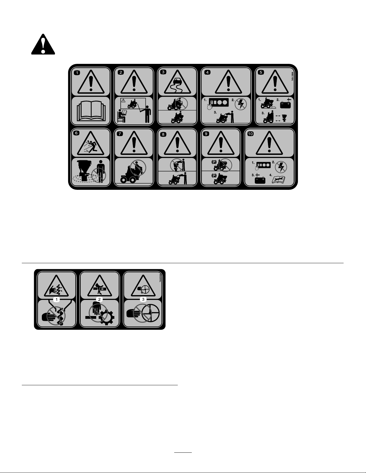
Safety and Instructional Decals . . . . . . . . . . . . . . . . . . . . . . . . . . 4
Setup ........................................................................ 5
Installing the Mounting Plates . . . . . . . . . . . . . . . . . . . . . . . . . . . . . 5
Drilling Mounting Holes on the Fender . . . . . . . . . . . . . . . . 6
Installing the Spreader on the Mounting
Plates .............................................................. 7
Installing the Controller . . . . . . . . . . . . . . . . . . . . . . . . . . . . . . . . . . . . . . . 8
Routing the Wire Harness . . . . . . . . . . . . . . . . . . . . . . . . . . . . . . . . . . . 9
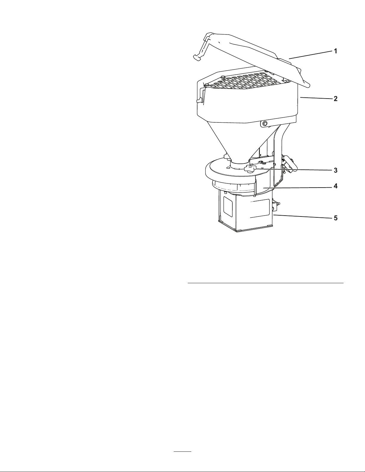
Product Overview . . . . . . . . . . . . . . . . . . . . . . . . . . . . . . . . . . . . . . . . . . . . . . . . . . . 10
Controls . . . . . . . . . . . . . . . . . . . . . . . . . . . . . . . . . . . . . . . . . . . . . . . . . . . . . . . . . . . 10
Specications . . . . . . . . . . . . . . . . . . . . . . . . . . . . . . . . . . . . . . . . . . . . . . . . . . . 1 1
Operation . . . . . . . . . . . . . . . . . . . . . . . . . . . . . . . . . . . . . . . . . . . . . . . . . . . . . . . . . . . . . . . . . 1 1
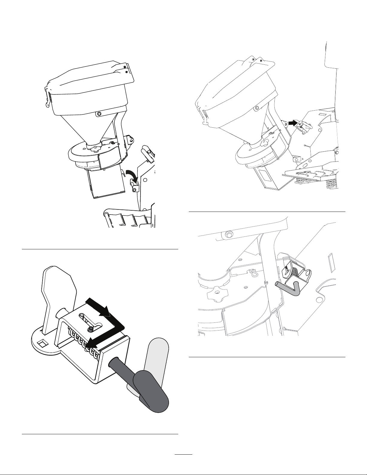
Removing the Spreader . . . . . . . . . . . . . . . . . . . . . . . . . . . . . . . . . . . . . 1 1
Loading the Spreader . . . . . . . . . . . . . . . . . . . . . . . . . . . . . . . . . . . . . . . 12
Operating the Spreader . . . . . . . . . . . . . . . . . . . . . . . . . . . . . . . . . . . . 12
Freeing a Clog . . . . . . . . . . . . . . . . . . . . . . . . . . . . . . . . . . . . . . . . . . . . . . . . . . 12
Adjusting the Material Deectors . . . . . . . . . . . . . . . . . . . . . . 12
Unloading the Spreader . . . . . . . . . . . . . . . . . . . . . . . . . . . . . . . . . . . . 12
Cleaning the Spreader . . . . . . . . . . . . . . . . . . . . . . . . . . . . . . . . . . . . . . 13
T roubleshooting . . . . . . . . . . . . . . . . . . . . . . . . . . . . . . . . . . . . . . . . . . . . . . . . . . . . . . 14
© 2023—BOSS Products
2010 The BOSS W ay
Iron Mountain, MI 49801
2
Contact us at www .bossplow .com.
Printed in the USA
All Rights Reserved

Safety
Improperly using and maintaining the equipment
can result in injury . T o reduce the potential for
injury , comply with these safety instructions.
Preparation
•Ensure that only trained personnel install and
perform maintenance on the equipment.
•Always wear appropriate personal protective
equipment when loading, unloading, and servicing
the spreader . W ear substantial, slip-resistant
footwear and eye protection.
•Carefully read and follow the chemical warning
labels and safety data sheets (SDSs) for all
chemicals used, and protect yourself according to
the chemical manufacturer's recommendations.
Operation
•Read the Owner ’ s Manual before operating or
servicing the spreader .
•Never put any part of your body between the
spreader and the vehicle.
•Overloading the spreader could result in
an accident or damage. Never exceed the
gross-vehicle-weight rating (GVWR).
•This spreader is restricted to the use of salt only .
Do not run other materials through the spreader .
•Do not attempt to mount or remove the spreader
with material in it.
•T urn the spreader of f before lling, mounting,
removing, servicing, or cleaning it.
•Never operate the spreader within 7.6 m (25 ft)
of bystanders.
•Do not climb into or ride on the spreader .
•Keep your hands, feet, and clothing away from
moving parts and mounting points.
•When transporting the spreader , ensure that it is
properly secured. Instructions are available at
www .bossplow .com .
•Do not store material in the hopper .
3

Safety and Instructional Decals
Safety decals and instructions are easily visible to the operator and are located near any area
of potential danger . Replace any decal that is damaged or missing.
decal143-1088
143-1088
1. W arning—read the Owner ’ s Manual .
6. Thrown object hazard—keep bystanders away .
2. W arning—all operators should be trained before operating
the machine.
7. W arning—do not stand or ride on the machine.
3. Loss of control hazard—do not overll the machine. 8. W arning—the machine must be installed before lling.
4. W arning—turn the machine of f before lling.
9. W arning—do not store materials in the machine.
5. W arning—empty the hopper and disconnect the power before
installing or removing the machine.
10. W arning—turn the machine of f and disconnect the power
before servicing the machine.
decaltgs05895b
TGS05895
1. W arning—severing of
ngers or hand in auger .
3. W arning—keep clear of
the moving spinner .
2. W arning—ngers or hand
entanglement in moving
parts.
4

Setup
Installing the Mounting
Plates
g383799
Figure 3
g382858
Figure 4
Installation location options
1. Secure the lower mounting plates to the machine
using 2 bolts (5/16-18 x 1 inch) and 2 nuts
(5/16-18 inch). For the Snowrator only , use the
single nut and bolt attached to the inside of the
fender as well ( Figure 5 ).
Important: Ensure that the mounting bar is
below the hardware slots when installing the
mounting plates.
•Use both brackets for the Snowrator .
•Use the outer bracket only for the Snowrator
MAG.
g446222
Figure 5
Snowrator
g387680
Figure 6
Snowrator MAG
2. Install the upper mounting bracket using 2 bolts
(5/16-18 x 1 inch) and 2 nuts (5/16-18 inch).
Note: If your fender does not have mounting
holes, proceed to Drilling Mounting Holes on the
Fender ( page 6 ) .
g382867
Figure 7
5

3. T orque the fasteners to 15 N∙m (1 1 ft-lb).
Drilling Mounting Holes on
the Fender
Note: This step is for machines without mounting
holes on the fenders. If your fenders do not have
mounting holes as shown in Figure 7 , you will need to
use the upper mounting bracket assembly as a guide
to drill holes in the fenders.
1. Attach the mounting bracket assembly to the
spreader by opening and then securing the latch
pin. Place the spreader mounting ange on the
mounting bar ( Figure 8 ).
g446273
Figure 8
1. Spreader
2. Mounting bracket
assembly
2. Rotate the spreader into the desired position
so that the mounting bracket is at against the
fender surface and the holes in the bracket are
3-3/4 inches away from the edge of the fender
(Figure 10 ).
g447492
Figure 9
1. 3-3/4 inches
3. Using the mounting holes, mark and drill 2 holes
(3/8 inch) Figure 10 ).
W ARNING
Using a drill without proper eye
protection may allow debris to enter the
eye, causing injury .
When drilling, always wear eye
protection.
g446284
Figure 10
1. Drill 2 holes (3/8 inch).
4. Proceed to do steps 2and 3in Installing the
Mounting Plates ( page 5 ) .
6

Installing the Spreader on
the Mounting Plates
1. Place the spreader mounting ange on the
mounting bar .
g382863
Figure 1 1
2. Pull back and lock the latch pin.
g382866
Figure 12
3. Rotate the spreader upright to the mounting
hole and spring bracket. Release the latch pin
to secure the assembly .
g382859
Figure 13
g382860
Figure 14
7

Installing the Controller
Installing the Controller on the
Snowrator MAG
1. Remove the cushion from the machine.
2. Remove the knockout panel on the control
panel.
g383797
Figure 15
3. Insert the controller into the opening and secure
it with 4 bolts (#10) and nuts.
g383796
Figure 16
Installing the Controller on the
Snowrator
1. Remove the cushion from the machine.
g319131
Figure 17
2. Remove the knockout panel on the control
panel.
g382864
Figure 18
3. Insert the controller into the opening and secure
it with 4 bolts (#10) and nuts.
8

g382856
Figure 19
Routing the W ire Harness
Important: Keep the harness away from hot or
moving parts.
g388640
Figure 20
1. Machine harness
connector
2. Controller connector
1. Connect the controller connector to the back
side of the previously installed control and
secure with cable ties.
9

2. Connect the spreader side harness to the
spreader connector . Route this harness over the
fender near the spreader latch pin.
3. Secure any excess wires with cable ties.
Product Overview
g382943
Figure 21
1. Lid
4. Material deector
2. Hopper 5. Motor box
3. Material deector
adjustment knob
Controls
Become familiar with all of the controls before you
operate the spreader .
Material Deector
The material deector controls the spread of materials;
you can adjust the controls to provide dif ferent spread
patterns; refer to Adjusting the Material Deectors
( page 12 )
10

Controller
The spreader controller lets you operate your spreader
and displays information about your machine.
g293836
Figure 22
1. Blast button
4. Slow button
2. Power button 5. Fast button
3. Speed LEDs
•Power button—turns the spreader controller and
spinner motor on or of f. Press once to turn the
controller on. Press again to turn the spinner motor
on or of f. Hold the button to turn the controller of f.
•Blast button—momentarily sends full power to the
spinner motor as long as it is held
•Fast button—increases the spinner motor speed
•Slow button—decreases the spinner motor speed
•Speed LEDs—indicates the spinner motor speed
and operating mode.
Specications
Note: Specications and design are subject to
change without notice.
Height
73.6 cm (28-32 inches)
Width
31.75 cm (12.5 inches)
Depth
51.4 cm (20.25 inches)
W eight (empty) 22.7 kg (50 lb)
Capacity 0.024 m
3
(0.85 ft
3
)
Operation
Note: Determine the left and right sides of the
machine from the normal operating position.
DANGER
The spreader is heavy and could cause
serious injury or property damage if it falls
off the vehicle.
• Ensure that your footing is stable, and
avoid lifting the spreader on slippery or
uneven surfaces.
Removing the Spreader
1. Disconnect the spreader wire harness.
2. Ensure that all material has been emptied from
the spreader .
3. Pull back and lock the latch pin.
Important: Hold the spreader in place when
unlocking the latch pin.
g382866
Figure 23
4. Rotate the spreader back and lift the spreader
mounting ange of f of the mounting bar .
1 1

g382945
Figure 24
Loading the Spreader
Important: Use only bag or bulk salt in the
spreader . Other materials could cause damage to
the machine.
1. Ensure that the spreader is securely mounted to
your machine and is not over slippery or uneven
terrain.
2. Open the hopper cover .
3. Determine the amount of material that you
can safely transport in your spreader; refer to
Specications ( page 1 1 ) .
4. Place the bag of material on the edge of the
hopper and open the top. Carefully pour the
contents into the hopper .
Note: Have 2 people lift bags weighing more
than 18 kg (40 lb).
5. Close and secure the hopper cover .
Operating the Spreader
1. Start the machine.
2. T urn on the spreader .
3. Set your desired spinner motor speed.
Note: The spinner motor speed determines
how far and how densely the material is spread.
Slow speeds spread material close and densely .
Fast speeds spread material far and thinly .
4. Drive at a consistent speed as you spread
material.
5. When you are nished spreading, turn the
spreader of f.
Freeing a Clog
If the clog is not cleared automatically , turn of f the
machine, disconnect the spreader wire harness, and
manually free the clog.
Adjusting the Material
Deectors
1. T urn the material deector knob counter
clockwise to loosen the material deector .
2. Slide the material deector into the desired
position.
3. T urn the material deector knob clockwise to
tighten the material deector .
g382948
Figure 25
Unloading the Spreader1. Position the spreader in the area where you
want to deposit the material.
2. T urn on the spreader controller and run the
spreader until the hopper is empty .
12

Cleaning the Spreader
Service Interval : Before each use or daily —Clean
the spreader .
Important: Do not use water to clean the
spreader .
Use compressed air to clear debris and materials from
the spreader and hopper .
13

T roubleshooting
Problem
Possible Cause Corrective Action
1. The controller is not plugged into the
wire harness.
1. Plug in the controller .
2. The electrical system is damaged.
2. Contact your authorized BOSS dealer .
The controller has no power .
3. A fuse is blown. 3. Replace the fuse.
1. The spreader and vehicle wire
harnesses are not connected.
1. Connect the wire harnesses.The spreader motor does not work.
2. The controller is not plugged into the
wire harness.
2. Plug in the controller .
Material is spreading too fast. 1. The feed gate is open too much. 1. Move the feed gate lever to the
appropriate setting.
1. The spinner disk is stuck.
1. Refer to the Freeing a Clog section.
2. The spinner shaft is bent. 2. Inspect the spinner shaft and replace
it if damaged.
2 LEDs on the controller are ashing.
3. The spinner disk is contacting the
material deector .
3. Clean of f the material deector .
1. There is a short between the controller
and the spreader .
1. Check the wire harness between the
spreader and controller . Repair or
replace it if damaged.
3 LEDs on the controller are ashing.
2. The spinner motor has an internal
short.
2. Replace the spinner motor .
1. The spreader is not connected to the
controller .
1. Connect the spreader to the controller .
2. The connection between the spreader
and controller connectors is bad.
2. Clean the connectors.
4 LEDs on the controller are ashing.
3. The spreader or controller are
connected to the wrong wire harness
connectors.
3. Ensure that the spreader and controller
are connected to the correct wire
harness connectors.
5 LEDs on the controller are ashing.
1. The battery voltage is low . 1. Increase the engine rpm and turn the
controller of f then on again. If the
problem persists, turn of f the vehicle
pump, lights, vibrator , and spreader ,
increase the engine rpm, and let the
machine run for several minutes.
Check the voltage until your volt meter
reads 12 V , then turn the controller of f
then on again.
6 LEDs on the controller are ashing.
1. The voltage regulator is bad. 1. Replace the voltage regulator .
7 LEDs on the controller are ashing.
1. The controller is overheating.
1. T urn the controller of f until it cools
down.
14

Notes:

This manual suits for next models
1
Table of contents
Other Boss Snowplow Spreader manuals

Boss Snowplow
Boss Snowplow TGS 300 Series User manual

Boss Snowplow
Boss Snowplow TGS 600 User manual

Boss Snowplow
Boss Snowplow SNR24030 User manual

Boss Snowplow
Boss Snowplow WBS15852 User manual

Boss Snowplow
Boss Snowplow TGS 800 User manual

Boss Snowplow
Boss Snowplow VBX 3000 User manual

Boss Snowplow
Boss Snowplow VBX 6500 User manual

Boss Snowplow
Boss Snowplow TGS 300 User manual

Boss Snowplow
Boss Snowplow WBS28080 User manual

Boss Snowplow
Boss Snowplow TGS 800 User manual