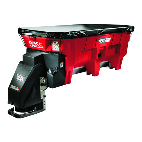
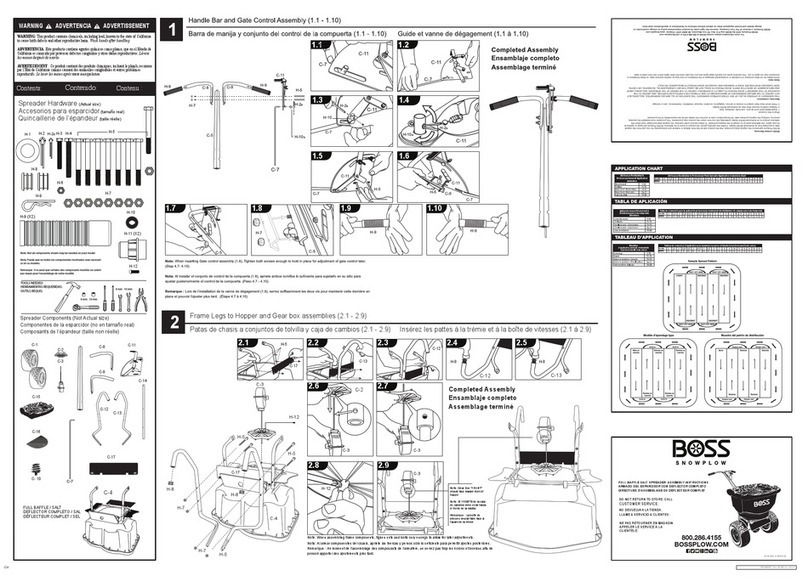
Boss Snowplow VBX 3000 User manual

FormNo.MSC11095RevB
Owner'sManual
VBX3000V-BoxSpreader
PartNo.VBS11060—SerialNo.400000000andUp
PartNo.VBS19300B—SerialNo.400000000andUp
Registeratwww.bossplow.com.
OriginalInstructions(EN)*MSC11095*

ThisproductcomplieswithallrelevantEuropean
directives;fordetails,pleaseseetheseparateproduct
specicDeclarationofConformity(DOC)sheet.
BOSSProductslimitedconsumerwarrantyandBOSS
Productscommercialwarrantypoliciesarelocatedat
www.bossplow.com.
Patentspending.
WARNING
CALIFORNIA
Proposition65Warning
Useofthisproductmaycauseexposure
tochemicalsknowntotheStateof
Californiatocausecancer,birthdefects,
orotherreproductiveharm.
Introduction
Readthisinformationcarefullytolearnhowtooperate
andmaintainyourproductproperlyandtoavoid
injuryandproductdamage.Youareresponsiblefor
operatingtheproductproperlyandsafely.
YoumaycontactBOSSdirectlyatwww.bossplow.com
forproductandaccessoryinformation,helpndinga
dealer,ortoregisteryourproduct.
Wheneveryouneedservice,genuineBOSSparts,or
additionalinformation,contactanAuthorizedBOSS
DealerorBOSST echnicalService()andhavethe
modelandserialnumbersofyourproductready.
Figure1identiesthelocationofthemodelandserial
numbersontheproduct.Writethenumbersinthe
spaceprovided.
g031521
Figure1
1.Serialnumberlocation
ModelNo.
SerialNo.
Thismanualidentiespotentialhazardsandhas
safetymessagesidentiedbythesafetyalertsymbol
(Figure2),whichsignalsahazardthatmaycause
seriousinjuryordeathifyoudonotfollowthe
recommendedprecautions.
g000502
Figure2
1.Safetyalertsymbol
Thismanualuses2wordstohighlightinformation.
Importantcallsattentiontospecialmechanical
informationandNoteemphasizesgeneralinformation
worthyofspecialattention.
Contents
Safety.......................................................................3
Preparation.........................................................3
Operation............................................................3
SafetyandInstructionalDecals..........................4
Setup........................................................................6
InstallingtheWireHarness.................................6
MountingtheSpreader.......................................7
InstallingtheTie-DownD-Rings..........................7
SecuringtheSpreader........................................8
InstallingtheSpinnerAssembly..........................8
InstallingtheSpreaderController........................9
ProductOverview...................................................10
Controls...........................................................10
Specications...................................................11
Operation.................................................................11
LoadingtheSpreader........................................11
OperatingtheSpreader....................................12
FreeingaClog..................................................12
AdjustingtheMaterialDeectors......................12
AdjustingtheBafe...........................................13
RemovingtheSpinnerAssembly......................13
UnloadingtheSpreader....................................13
OperatingTips.................................................14
Maintenance...........................................................15
RecommendedMaintenanceSchedule(s)...........15
Lubrication..........................................................15
GreasingtheMachine.......................................15
Storage...................................................................15
Troubleshooting......................................................16
©2021—BOSSProducts
P .O.Box787
IronMountain,MI498012
Contactusatwww.bossplow.com.
PrintedintheUSA
AllRightsReserved


Safety
Improperuseormaintenancebytheoperatoror
ownercanresultininjury.Toreducethepotential
forinjury,complywiththesesafetyinstructions
andalwayspayattentiontothesafety-alert
symbol,whichmeans:Caution,Warning,or
Danger—personalsafetyinstruction.Failureto
complywiththeinstructionmayresultinpersonal
injuryordeath.
Preparation
•ReadtheOwner’sManualbeforeoperatingor
servicingthespreader.
•Ensurethatonlytrainedpersonnelinstallsand
performsmaintenanceontheequipment.
•Usea500kg(1/2ton)minimumliftingdeviceto
moveheavyspreadercomponents.Neverputany
partofyourbodyunderasuspendedload.
•Thisspreaderhasanoperatingsoundlevelbelow
70dBAwhileinsidethevehicle.Wearhearing
protectionwhileoperatingthespreaderoutside
ofthevehicle.
•Alwayswearappropriatepersonalprotective
equipmentwhenloading,unloading,andservicing
thespreader.Wearsubstantial,slip-resistant
footwear,cold-weatherclothing,hardhat,safety
glasses,anddustprotection.
Operation
•Neverputanypartofyourbodybetweenthe
spreaderandthevehicle.
•Whentransportingthespreader,ensurethatitis
properlysecured.Instructionsareavailableat
www.bossplow.com.
•Materialsafetydatasheets(MSDS)areavailable
atwww.bossplow.com.
•Donotoperatethemachinewhileill,tired,or
undertheinuenceofalcoholordrugs.
•Forvehiclemountedspreaders,alwaysfollow
themanufacturer’srecommendationsforproper
parkingprocedures.
•Alwayswearyourseatbeltwhileoperatingamotor
vehicle.
•Donotexceed22km/h(14mph)whilespreading.
•Overloadingthespreadercouldresultin
anaccidentordamage.Neverexceedthe
gross-vehicle-weightrating(GVWR),thefront
orreargross-axle-weightratings(FGAWRor
RGAWR),ortheutilityvehiclebedcapacity.
•Thisspreaderisrestrictedtotheuseofdry,
free-owingsalt.Donotrunothermaterials
throughthespreader.
•Donotattempttomountorremovethespreader
withmaterialinit.
•Turnthevehicleandspreaderoffbeforelling,
mounting,removing,servicing,orcleaningit.
•Donotoperatethespreaderwithin7.6m(25ft)
ofbystanders.
•Donotclimbintoorrideonthespreader.
•Keepyourhands,feet,andclothingawayfrom
movingpartsandmountingpoints.
•Mountthespreadertoavehiclewhenloading
material.
•Installratchetstrapsandkeepthemproperly
tightenedatalltimes.
•Donotstorematerialinthehopper.
3

SafetyandInstructionalDecals
Safetydecalsandinstructionsareeasilyvisibletotheoperatorandarelocatednearanyarea
ofpotentialdanger.Replaceanydecalthatisdamagedormissing.
decalmsc19399
MSC19399
1.Warning—readthe
Operator’sManual.
4.Warning—donotoperate
themachinewithan
overloadedhopper.
2.Warning—receivetraining
forthismachine.
5.Warning—donotraise
thevehiclebedwhenthe
spreaderisinstalled.
3.Tippinghazard—onlydrive
sidetosideonslopesless
than10°.
6.Tippinghazard—onlydrive
upslopeslessthan15°.
decalmsc19312b
MSC19312
1.Cutting/dismemberment
hazard,spinner—keep
handsclear.
2.Entanglementhazard;
auger—keephandsclear.
decalvbs14567b
VBS14567
1.Lossofmachinehazard—theratchetstrapsmustbe
securedatalltimes.
4

decalmsc06370
MSC06370
(non-replaceabledecal)
1.Feederspeed4.Vibrator
2.Power5.Blast
3.Light6.Spinnerspeed
5

Setup
Determinetheleftandrightsidesofthemachinefrom
thenormaloperatingposition.
InstallingtheWireHarness
DANGER
Vehicleenginescontainmovingpartsandcan
becomeextremelyhot,capableofcausing
severeburnsandseriousbodilyharm.
Shutofftheengineandallowitsufcienttime
tocooldownbeforeinstallingthiskit.
DANGER
Vehiclebatteriescancausedangerous
electricalshocksthatcouldleadtosevere
burnsordeath.
Disconnectyourbatterybeforeinstalling
thiskitbyremovingthenegativeconnector
followedbythepositiveconnector.
1.Securethespreaderconnectorsendofthe
vehiclewireharness(Figure3)totheleftsideof
therearvehiclebumperwithacabletie.
2.Routethewireharnessalongthedriver-side
frame-railandintotheenginecompartment,and
secureitwithcableties.
Note:Keepthewireharnessawayfromany
hotormovingparts.
3.Insertthecontrollerconnectors,spade
connector,andgroundcablethroughtheengine
compartmentwallandintothevehiclecab,and
securethemwithcableties.
Note:Routetheconnectorstothelocationthat
youwanttoinstallyourcontroller.
4.Connecttheblackringconnectorintheengine
compartmenttothenegative(-)batteryterminal
(Figure3).
5.Connecttheredringconnectorintheengine
compartmenttothepositive(+)batteryterminal
(Figure3).
6.Connectthespadeconnectortoanignition
switchpowersourceonthevehicle(Figure3).
7.Connectthegroundcabletothenegative(–)
batterypostorchassisground(Figure3).
8.Wrapalloftheexcesswireandsecureitinthe
enginecompartmentwithcableties.
g239091
Figure3
1.Controllerconnectors4.Spadeconnector
2.Blackringconnector5.Groundcable
3.Redringconnector6.Spreaderconnectors
6

MountingtheSpreader
Theminimumtruckbedlengthforthespreaderis85
cm(33-1/2inches).
1.Removethetailgatefromthevehicle.
2.Usingtheliftpoints(Figure4),liftthespreader
ontotheutilityvehiclebedandsetitonthe
centerline.
g031522
Figure4
1.Liftpoints
3.Slidethespreadertowardthevehiclecabuntil
theslidestopfeethittheutilityvehiclebed
(Figure5).
Note:Theutilityvehiclebedmustbeatleast85
cm(33-1/2inches)long.
g031523
Figure5
1.Stopfeet2.Edgeoftheutilityvehicle
bed
InstallingtheTie-Down
D-Rings
1.Usinga7/16-inchdrillbit,markanddrillthe
holesfortheD-ringsasshowninFigure6.
AligntherearD-ringwiththebackoftherear
spreaderleg.
Note:Drilltheholesthroughorneartheframe
cross-membersofyourvehicle.
g031524
Figure6
1.D–ringcentertotheD–ringcenter—minimumof76cm(30
inches)
2.InstalltheD-ringsasshowninFigure7and
torquetheboltsto28Nm(19.7ft-lb).
g031525
Figure7
1.Bolt(1–1/2inch)4.Bedmountplate
2.Flatwasher(3/8inch)5.Flatwasher(3/8inch)
3.D-ring6.Locknut
7

SecuringtheSpreader
DANGER
Thespreaderisheavyandcouldcause
seriousinjuryorpropertydamageifitfalls
offthevehicle.
Ensurethattheratchetstrapsaresecurely
attachedtothespreaderatalltimes.
1.Connecttheratchetstrapstothelifthandles
aroundtheupperedgeofthespreader(Figure
8).
g031526
Figure8
1.Lifthandle3.D-ring
2.Ratchetstrap
2.Connectthefreeendsoftheratchetstrapsto
theD-ringsoppositetothemoneachsideofthe
spreader(Figure8).
Note:Theratchetstrapsshouldcrossonthe
sidesofthespreader.
3.Tightenthestrapsevenlytosecurethespreader.
InstallingtheSpinner
Assembly
1.Attachthetethertothelowerboltoneachofthe
hopperlatches(Figure9).
g031633
Figure9
1.Hopperlatch4.Tether
2.Rubberwasher5.Lowerbolt
3.Thumbscrew
2.Attachtheopenendofthetethertothe
thumbscrewusingarubberwasher(Figure9).
3.Attachthespinnerassemblytothespreaderand
secureitwiththethumbscrews(Figure10).
Important:Thespinnerassemblyisheavy
andrequires2peopletolift.
Note:Avoidpinchingngersonthehopper
latchwhenmountingthespinnerassembly.
g031527
Figure10
1.Spinnerassembly2.Thumbscrew
4.Connectthewireharness.
8

InstallingtheSpreader
Controller
Mountthecontrollerinthecabwhereitdoesnot
interferewithvehicleoperationorvisibility.Ensure
thatthecontrollerisinadryareathatisprotected
fromtheelements.
Important:Donotmountthecontrollerina
locationthatvehicleoccupantscouldcontactit
duringacrash.
1.Attachthemountingbrackettothevehicleusing
2sheet-metalscrews(Figure11).
g239094
Figure11
1.Thumbscrew3.Mountingbracket
2.Starwasher4.Sheet-metalscrew
2.Attachthecontrollertothemountingbracket
using4starwashersand2thumbscrews(Figure
11).
Note:Positionthecontrollerscreensothatitis
clearlyvisibletothedriver.
3.Connectthewireharnesscontrollerconnectors
tothecontroller(Figure12).
g239263
Figure12
9

ProductOverview
g031529
Figure13
1.Materialdeector3.Hoppercover
2.Spinnerassembly
Controls
MaterialDeector
Thematerialdeectorcontrolsthespreadofmaterials;
youcanadjustthecontrolstoprovidedifferentspread
patterns;refertoAdjustingtheMaterialDeectors
(page12).
SpreaderController
Thespreadercontrollerletsyouoperateyourspreader
anddisplaysinformationaboutyourmachine.
g246333
Figure14
1.Feedspeeddial7.Spinnerspeeddisplay
2.Feedspeeddisplay8.Spinnerspeeddial
3.PowerLED9.Blastbutton
4.LightLED10.Vibratorbutton
5.VibratorLED11.Lightbutton
6.BlastLED12.Powerbutton
•Feedspeeddial—increasesthefeedermotor
speedwhenturnedclockwise,anddecreasesthe
feedermotorspeedwhenturnedcounterclockwise
•Feedspeeddisplay—showsthefeedermotor
speed
•PowerLED—whengreen,itindicatesthatthe
controllerisonorthemotorsarerunning.When
amber,itindicatesthatthespreaderisclearing
10

ajam.Whenashingred,itindicatesthatthe
spreaderisjammedorhasbeendisconnected.
Thespeeddisplayforthejammedmotorashes
toindicatewherethejamis.
•LightLED—indicatesthattherearlightison
•VibratorLED—indicatesthatthevibratoris
enabled.Itblinkswhilethevibratorisrunning.
•BlastLED—indicatesthattheBlastfunctionis
beingused
•Spinnerspeeddisplay—showsthespinnermotor
speed
•Spinnerspeeddial—increasesthespinner
motorspeedwhenturnedclockwise,and
decreasesthespinnermotorspeedwhenturned
counterclockwise
•Powerbutton—turnsthespreadercontrollerand
motorsonoroff.Ifthecontrollerisnotactive,
pressingthebuttonturnsiton.Ifthecontrolleris
active,pressingthebuttonstartsthespinnerand
feedermotorsandthevibrator(ifenabled).Ifthe
spinnerandfeedermotorsareon,pressingthe
buttonturnsthemoff.Holdingthebuttonfor3
secondsturnsoffthemotorsandcontroller.
•Lightbutton—turnstherearlightonoroff
•Vibratorbutton—switchesthevibratoronoroff
whenthefeedermotorison
•Blastbutton—momentarilysendsfullpowertothe
spinnerandfeedermotorsaslongasitispressed
Specications
Note:Specicationsanddesignaresubjectto
changewithoutnotice.
Length132cm(52inches)
Hopperheight71cm(28inches)
Hopperwidth127cm(50inches)
Weight(empty)104kg(230lb)
Capacity0.34m3(12ft3)
Operation
Note:Determinetheleftandrightsidesofthe
machinefromthenormaloperatingposition.
LoadingtheSpreader
Important:Onlyusedrysaltorcinder/saltmixes
inthespreader.Othermaterialscouldcause
damagetothemachine.
Thedensityofmaterialsthatcanbeloadedintothe
spreadervariesandthereforesowilltheamountof
agivenmaterialthatcanbecarriedbythespreader
beforethemaximumloadratingisreached.
Important:Whenllingthespreader,donot
exceedthegross-vehicle-weightrating(GVWR),
gross-axle-weightrating(GAWR),orthecapacity
oftheutilityvehiclebed.
1.Ensurethatthespreaderissecurelymountedto
thevehicleandthatthetopscreenisinstalled.
2.Removethetarp.
3.Determinetheamountofmaterialthatyoucan
safelytransportusingtheGVWR/GAWRofthe
vehicleandthefollowingtable.
MaterialTypeWeightRange
Finesalt1,121to1,281kg/m3(70to80
lb/ft3)
Coarsesalt721to961kg/m3(45to60
lb/ft3)
Cinders641kg/m3(40lb/ft3)
4.Fillthespreaderevenlywiththematerial,making
surenottollpastthetopofthehopper.
Important:Overllingthehoppercould
damagethespreaderandthevehicle.
11

OperatingtheSpreader
DANGER
Hands,feet,andclothingcangetcaughtin
themovingpartsofthespreaderandcause
seriousbodilyinjuryandlossoflimbs.
Keepyourhands,feet,andclothingawayfrom
themovingspinnerandattachmentpoints.
CAUTION
Thespreaderthrowsmaterialatahighspeed
thatcouldcauseminorinjuriestobystanders.
Bystandersshouldstayaminimumof7.6m
(25ft)awayfromoperatingspreaders.
1.Startthevehicle.
2.PressthePowerbuttontoturnonthespreader
controller.
3.PressthePowerbuttonasecondtimeto
activatethespreader.
Note:Alwayscheckforbystandersbefore
startingthespreader.
4.Usethedialstosetyourdesiredspinnerand
feederspeeds.
Note:Thefeedspeeddetermineshowquickly
thematerialisspread.Thespinnerspeed
determineshowfaritisthrown.
5.Whilespreading,youcanpresstheBlastbutton
tomomentarilyincreasethespeedofthespinner
andfeedermotors.
6.PressthePowerbuttonwhenyouarenished
spreadingtostopthespreader.
7.PressandholdthePowerbuttonfor3seconds
orturnoffyourvehicletoturnoffthespreader
controller.
FreeingaClog
ThepowerLEDonthespreadercontrollerashes
orangeandthefeedorspinnerspeeddisplayashes
whendebrisgetswedgedinthespreader.Iftheclog
isnotclearedautomatically,thepowerLEDashes
red.Ifthishappens,disconnectthespreaderwire
harnessandmanuallyfreetheclog.
AdjustingtheMaterial
Deectors
Youcanadjustthematerialdeectorsbyinsertingthe
deectorpinsintothestaggeredholesaroundthe
spinner(Figure15).
g348626
Figure15
1.Materialdeector2.Adjustmentholes
Youcanadjustthespreadpatternbypositioningthe
deectorsasshowninFigure16.
g029499
Figure16
DeectionSettings
1.Driversideopen3.Bothsidesopen
2.Passengersideopen
12

AdjustingtheBafe
1.Emptythespreaderhopper;refertoUnloading
theSpreader(page13).
2.Unplugthespinnerharnessfromthemainwire
harness.
3.Removethetopscreenfromthespreader.
4.Removethehardwaresecuringthebafetothe
insideofthespreader(Figure17).
g246797
Figure17
1.Bafe
5.Raiseorlowerthebafetothedesiredheight
andsecureitwiththepreviouslyremoved
hardware(Figure17).
Note:Raisingthebafeincreasestheowrate
andloadonthefeeder.Loweringthebafe
decreasestheowrateandloadonthefeeder.
6.Securethepreviouslyremovedtopscreen,and
connectthespinnerharnesstothemainwire
harness.
RemovingtheSpinner
Assembly
1.Unplugthespinnerharnessfromthemainwire
harness.
2.Removethe2thumbscrewssecuringthe
spinnerassemblytothehopper(Figure18).
g031527
Figure18
1.Spinnerassembly2.Thumbscrew
3.Removethespinnerassembly.
DANGER
Thespinnerassemblyisheavyandcould
causeseriousinjuryifdropped.
Ensurethatyourfootingisstable,and
avoidremovingthespinnerassembly
nearslipperyorunevensurfaces.
UnloadingtheSpreader
Important:Donotleavematerialinthehopperas
itcoulddamagethemachine.
1.Positionthespreaderintheareawhereyou
wanttodeposityourmaterial.
2.Unplugthespinnerharnessfromthemainwire
harness.
3.Removethethumbscrewsfromthespinner
assembly(Figure18).
4.Removethespinnerassemblyfromthehopper
(Figure18).
5.TurntheFeedSpeeddialto9tounloadthe
hopper.
6.Oncethehopperisempty,attachthespinner
assemblytothehopperandsecureitwiththe
previouslyremovedthumbscrews.
7.Connectthespinnerharnesstothemainwire
harness.
13

OperatingTips
•Knowtheareainwhichyouareworking;hidden
obstructionssuchascurbs,sidewalks,andpipes,
candamagethespreaderorvehicle.
•Donotlettheicebuildup;alwaysstartassoon
aspossible.
•Alwayswearyourseatbeltwhenspreading.
•Alwaysremembertospreadatasafespeed.
•Neverrideonorputbodypartsintothespreader
whileservicingoroperatingit.
14

Maintenance
WARNING
Failuretoproperlymaintainthemachinecouldresultinprematurefailureofmachinesystems
causingpossibleharmtoyouorbystanders.
Keepthemachinewellmaintainedandingoodworkingorderasindicatedintheseinstructions.
Note:Determinetheleftandrightsidesofthemachinefromthenormaloperatingposition.
RecommendedMaintenanceSchedule(s)
MaintenanceService
IntervalMaintenanceProcedure
Beforeeachuseordaily•Checktheratchetstrapsandtightenasnecessary.
Every20hours
•Cleanthechuteofanybuildup.
•Greasethebearings.
•Tightenthehardware.
Beforestorage•Unloadthespreader.
•Cleanandgreaseallofthebearings.
Lubrication
GreasingtheMachine
Every20hours—Greasethebearings.
GreaseallofthebearingswithaNo.2lithiumgrease.
Storage
1.Unloadthespreader;refertoUnloadingthe
Spreader(page13).
2.Removethespreaderfromthevehicleusingthe
lifthandles;refertoProductOverview(page10).
3.Washandrinsetheentiremachine.
4.Cleanandgreaseallthebearings.
5.Cleanallexposedconnectorsandapply
dielectricgreasetothem.
6.Removethecontrollerfromtheutilityvehicle
andstoreitinaclean,dryplace.
15

Troubleshooting
ProblemPossibleCauseCorrectiveAction
1.Thespadeconnectorisnotconnected
totheignitionswitchpowersource.
1.Connectthespadeconnectortothe
ignitionswitchpowersource.
2.Thetheignitionswitch,battery,or
groundconnectionsarecorroded.
2.Cleantheignitionswitch,battery,and
groundconnections.
3.Thevehiclesidecircuitfuse,70A
in–linefuse,or5Ain-linefuseinthe
vehiclesideharnessisbad.
3.Replacethefuses.
Thecontrollerhasnopower.
4.Thecontrollerisnotpluggedintothe
wireharness.
4.Pluginthecontroller.
1.Thespreaderandvehiclewire
harnessesarenotconnected.
1.Connectthewireharnesses.
2.Thecontrollerisnotpluggedintothe
wireharness.
2.Pluginthecontroller.
Thespinnermotordoesnotworkorthe
PowerLEDisred.
3.Thespinnermotorisnotconnectedto
thespreadersideharness.
3.Connectthewireharnesses.
1.Thespreaderandvehiclewire
harnessesarenotconnected.
1.Connectthewireharnesses.
2.Thecontrollerisnotpluggedintothe
vehiclewireharness.
2.Pluginthecontroller.
ThePowerLEDisredorthefeedermotor
doesnotwork.
3.Thefeedermotorisnotconnectedto
thespreaderwireharness.
3.Connectthewireharnesses.
ThePowerLEDisashingredandthe
feedspeeddisplayisashing.
1.Thefeedmotorisjammed.1.RefertotheFreeingaClogsection.
ThePowerLEDisashingredandthe
spinnerspeeddisplayisashing.
1.Thespinnermotorisjammed1.RefertotheFreeingaClogsection.
1.Theconnectionbetweenthespinner
andthemotorshaftisbad.
1.ContactyourAuthorizedService
Dealer.
Thespinnermotorworksbutthespinner
isnotturning.
2.Theconnectionbetweenthemotor
shaftandthemotorhubisbad.
2.ContactyourAuthorizedService
Dealer.
1.Theconnectionbetweenthefeeder
andthemotorshaftisbad.
1.ContactyourAuthorizedService
Dealer.
Thefeedmotorworksbutthefeederis
notturning.
2.Theconnectionbetweenthemotor
shaftandthemotorhubisbad.
2.ContactyourAuthorizedService
Dealer.
TheLightLEDisashingred.1.Therearlightisburntoutor
disconnected.
1.Checktheconnection,andreplacethe
bulbifnecessary.
TheVibratorLEDisashingred.1.Thevibratorisdisconnectedorbroken.1.Checkthevibratorconnection,and
replacethevibratorifnecessary.
16
This manual suits for next models
2
Table of contents
Other Boss Snowplow Spreader manuals

Boss Snowplow
Boss Snowplow SNR24030 User manual

Boss Snowplow
Boss Snowplow TGS 800 User manual

Boss Snowplow
Boss Snowplow WBS15852 User manual

Boss Snowplow
Boss Snowplow TGS 800 User manual

Boss Snowplow
Boss Snowplow MSC22875B User manual

Boss Snowplow
Boss Snowplow VBX 6500 User manual

Boss Snowplow
Boss Snowplow TGS 300 User manual

Boss Snowplow
Boss Snowplow WBS28080 User manual

Boss Snowplow
Boss Snowplow TGS 600 User manual

Boss Snowplow
Boss Snowplow TGS 300 Series User manual