Boss Snowplow TGS 800 User manual

P.O. Box 787
Iron Mountain, MI 49801
United States
FormNo.TGS06487RevA
Owner'sManual
TGS800TailgateSpreader
PartNo.TGS08000
Registeratwww.bossplow.com.
OriginalInstructions(EN)*TGS06487*A

ThisproductcomplieswithallrelevantEuropeandirectives;
fordetails,pleaseseetheseparateproductspecicDeclaration
ofConformity(DOC)sheet.
WARNING
CALIFORNIA
Proposition65Warning
Thisproductcontainsachemicalorchemicals
knowntotheStateofCaliforniatocausecancer,
birthdefects,orreproductiveharm.
PatentsPending.
Introduction
Thistailgatespreaderisdesignedtospreadsaltonicyor
snowysurfaces.
Readthisinformationcarefullytolearnhowtooperateand
maintainyourproductproperlyandtoavoidinjuryand
productdamage.Youareresponsibleforoperatingthe
productproperlyandsafely.
YoumaycontactBOSSdirectlyatwww.bossplow.comfor
productandaccessoryinformation,helpndingadealer,or
toregisteryourproduct.
Wheneveryouneedservice,genuineBOSSparts,or
additionalinformation,contactanAuthorizedServiceDealer
orBOSSCustomerServiceandhavethemodelandserial
numbersofyourproductready.Figure1identiesthe
locationofthemodelandserialnumbersontheproduct.
Writethenumbersinthespaceprovided.
G031005 1
g031005
Figure1
1.Serialnumberlocation
ModelNo.
SerialNo.
Thismanualidentiespotentialhazardsandhassafety
messagesidentiedbythesafetyalertsymbol(Figure2),
whichsignalsahazardthatmaycauseseriousinjuryordeath
ifyoudonotfollowtherecommendedprecautions.
g000502
Figure2
1.Safetyalertsymbol
Thismanualuses2wordstohighlightinformation.
Importantcallsattentiontospecialmechanicalinformation
andNoteemphasizesgeneralinformationworthyofspecial
attention.
Contents
Safety...........................................................................3
Preparation.............................................................3
Operation...............................................................3
SafetyandInstructionalDecals.................................4
Setup............................................................................6
InstallingtheWireHarness.......................................6
InstallingtheSlide-InAttachment..............................6
MountingtheSpreaderwiththeSlide-In
Attachment.........................................................6
InstallingtheRT3Attachment..................................7
MountingtheSpreaderwiththeRT3
Attachment.........................................................8
InstallingtheSpreaderController..............................9
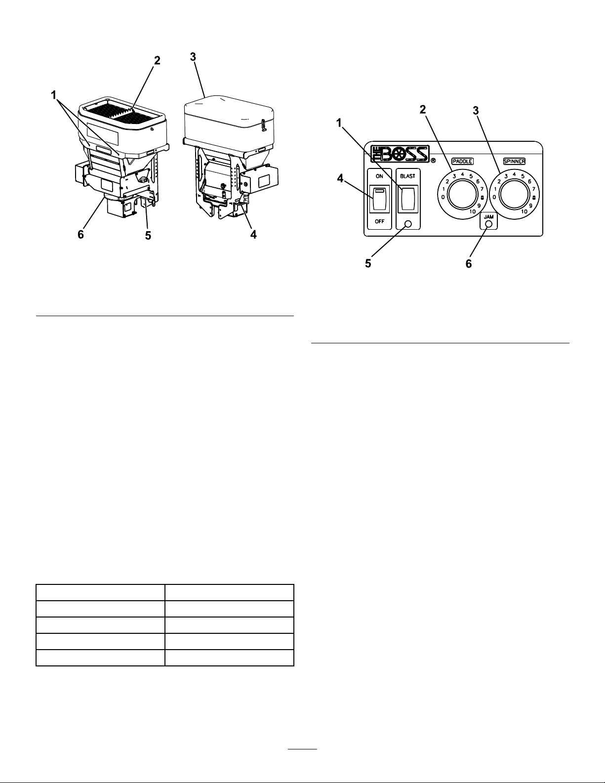
ProductOverview.........................................................10
Controls...............................................................10
Specications........................................................10
Operation....................................................................11
RemovingtheSpreader...........................................11
MountingtheSpreader............................................11
RemovingtheSpreader...........................................12
MountingtheSpreader............................................12
LoadingtheSpreader..............................................13
OperatingtheSpreader...........................................14
FreeingaClog........................................................14
UnloadingtheSpreader...........................................14
AdjustingtheMaterialDeectors.............................15
AdjustingtheRubberFlaps......................................15
AdjustingtheSpreaderVibration..............................16
OperatingTips......................................................16
Troubleshooting...........................................................17
©2016—BOSSProducts
P .O.Box787
IronMountain,MI498012
Contactusatwww.bossplow.com.
PrintedintheUSA
AllRightsReserved

Safety
Improperlyusingandmaintainingtheequipmentcan
resultininjury.Toreducethepotentialforinjury,
complywiththesesafetyinstructionsandalways
payattentiontothesafety-alertsymbol,which
means:
Caution
,
W ar ning
,or
Danger
—personalsafety
instruction.Failuretocomplywiththeinstructionmay
resultinpersonalinjuryordeath.
Preparation
•Ensurethatonlytrainedpersonnelinstallandperform
maintenanceontheequipment.
•Alwayswearappropriatepersonalprotectiveequipment
whenloading,unloading,andservicingthespreader.
Wearsubstantial,slip-resistantfootwear,cold-weather
clothing,safetyglasses,anddustprotection.
•Ensurethatyourrearviewmirrorisinagoodoperating
position.
•Manytrucksareequippedwithairbags.Neverdisable,
remove,orrelocateanysensorsorothercomponents
relatedtotheoperationoftheairbags.
•TGS800spreaderswithslide-inorRT3attachmentsmust
onlybeusedwithaminimumClassIVreceiverhitch.Do
notexceedthevehiclehitchrating.
•TheTGS800canholdamaximumweightof362kg(800
lb)ofsalt.Donotexceedthisweight.
Operation
•ReadtheOperator’sManualbeforeoperatingorservicing
thespreader.
•Donotoperatethemachinewhileill,tired,orunderthe
inuenceofalcoholordrugs.
•Forvehicle-mountedspreaders,alwaysfollowthe
manufacturer’srecommendationsforproperparking
procedures.
•Alwayswearyourseatbeltwhileoperatingamotorvehicle.
•Donotexceed22.5km/h(14mph)whilespreading.
•Thisspreaderhasanoperatingsoundlevelbelow70dBA.
•Neverputanypartofyourbodybetweenthespreader
andthevehicle.
•Overloadingthespreadercouldresultinanaccidentor
damage.Neverexceedthegross-vehicle-weightratingor
thefrontorreargross-axle-weightratingsforthevehicle.
•Thisspreaderisrestrictedtotheuseofsand,salt,ora
sand/saltmixonly.Donotrunothermaterialsthrough
thespreader.
•Donotattempttomountorremovethespreaderwith
materialinit.
•Turnthespreaderoffbeforelling,mounting,removing,
servicing,orcleaningit.
•Neveroperatethespreaderwithin7.6m(25ft)of
bystanders.
•Donotclimbintoorrideonthespreader.
•Keepyourhands,feet,andclothingawayfrommoving
partsandmountingpoints.
•Mountthespreadertoavehiclebeforeloadingmaterial.
•Installratchetstrapsandkeepthemproperlytightened
withtheslide-inandRT3Attachments.
•Whentransportingthespreader,ensurethatitisproperly
secured.Instructionsareavailableatwww .bossplow .com.
•Theslide-inattachmentmustbefullyengagedandpinned
intothevehicle’s5cm(2inch)receiverhitch.
•TheupperandlowerpinsoftheRT3attachmentmust
befullyengagedandpinnedintothevehicle’s5cm(2
inch)receiverhitch.
•Materialsafetydatasheets(MSDS)areavailableat
www.bossplow.com.
•Usea1/2tonminimumliftingdevicetomoveheavy
spreadercomponents.
•Donotstorematerialinthehopper.
3

SafetyandInstructionalDecals
Safetydecalsandinstructionsareeasilyvisibletotheoperatorandarelocatednearanyareaofpotential
danger.Replaceanydecalthatisdamagedormissing.
decaltgs06269b
TGS06269
1.Warning—readtheOwner’s
Manual.
4.Warning—turnthemachine
offbeforelling.
7.Warning—donotstandor
rideonthemachine.
10.Warning—turnthemachine
offanddisconnectthe
powerbeforeservicingthe
machine.
2.Warning—alloperators
shouldbetrainedbefore
operatingthemachine.
5.Warning—emptythe
hopperanddisconnectthe
powerbeforeinstallingor
removingthemachine.
8.Warning—themachine
mustbeinstalledbefore
lling.
3.Lossofcontrolhazard—do
notoverllthemachine.
6.Thrownobject
hazard—keepbystanders
asafedistancefromthe
machine.
9.Warning—donotstore
materialsinthemachine.
decaltgs05895b
TGS05895
1.Cutting/dismemberment
hazard;auger—keep
ngersandhandsclearof
theauger.
3.Cutting/dismemberment
hazard;spinner—keep
ngersandhandsclearof
thespinner.
2.Crushinghazard—keep
ngersandhandsclearof
movingparts.
decaltgs15606
TGS15606
1.Lossofmachinehazard—theratchetstrapsmustbe
securedatalltimes.
4

decalmsc14468
MSC14468
1.ReadtheOwner’s
Manualforinformation
onattachingthespreader.
4.ReadtheOwner’s
Manualforinformation
onremovingthespreader.
2.Couplerspringpinunlock5.Couplerspringpinlock
3.Couplerspringpinunlock
position
6.Couplerspringpinlock
position
decaltgs05896
TGS05896
1.Important—readthe
Owner’sManual.
2.Thelockpinmustbefully
engagedbeforeusingthe
machine.
5

Setup
Note:Eithertheslide-inorRT3attachmentisrequiredto
installthismachine.ContactyourAuthorizedBOSSDealer
formoreinformation.
InstallingtheWireHarness
DANGER
Vehicleenginescontainmovingpartsandcan
becomeextremelyhot,capableofcausingsevere
burnsandseriousbodilyharm.
Shutofftheengineandallowitsufcienttimeto
cooldownbeforeinstallingthiskit.
DANGER
Vehiclebatteriescancausedangerouselectrical
shocksthatcouldleadtosevereburnsordeath.
Disconnectyourbatterybeforeinstallingthiskit.
1.Securethespreaderendofthevehiclewireharness
(Figure3)tothecenteroftherearvehiclebumperwith
acabletie.
2.Routethewireharnessalongthedriver-sideframe-rail
andintotheenginecompartment,andsecureitwith
cableties.
Note:Keepthewireharnessawayfromanyhotor
movingparts.
3.Insertthecontrollerconnectorsthroughtherewall
andintothevehiclecab,andsecurethemwithcable
ties.
Note:Routetheconnectorstothelocationthatyou
wanttoinstallyourcontroller.
4.Connecttheblackringconnectortothenegative(-)
batteryterminal(Figure3).
5.Connecttheredringconnectortothepositive(+)
batteryterminal(Figure3).
6.Wrapalloftheexcesswireandsecureitintheengine
compartmentwithcableties.
g186472
Figure3
1.Redringconnector3.Controllerconnector
2.Blackringconnector4.Spreaderconnector
InstallingtheSlide-In
Attachment
1.Mounttheslide-inattachmenttothespreaderusing4
bolts(1/2inch)andlocknuts(1/2inch)andtorquethe
boltsto76Nm(56ft-lb)asshowninFigure4.
1
234
G031007
g031007
Figure4
1.Spinnerguard3.Bolt(1/2inch)
2.Locknut(1/2inch)4.Slide-inattachment
2.Mountthespinnerguardtothespreaderusingthe2
existingbolts(3/8inch)andlocknuts(3/8inch)and
torquetheboltsto27Nm(19.7ft-lb)asshownin
Figure4.
MountingtheSpreaderwith
theSlide-InAttachment
1.AttachtheD-ringendoftheratchetstrapstotheupper
holesontheoutsideofthespreaderframeusingabolt
(1/2inch),washer(1/2inch),andlocknut(1/2inch)
andtorquetheboltsto76Nm(56ft-lb)asshownin
Figure5.
1234
G031008
g031008
Figure5
1.Locknut(1/2inch)3.Washer(1/2inch)
2.Ratchetstrap4.Bolt(1/2inch)
6

2.Slidethehitchonthespreaderintothereceiverhitch
ofyourvehicleandlineupthesecondholeonthe
spreaderhitchwiththeholeinthehitchofyourvehicle
(Figure6).
Note:Ifthespreadercontactsthebumperofyour
vehicle,slidethespreaderoutandaligntherstholeof
thespreaderhitchinstead.
DANGER
Thespreaderisheavyandcouldcauseserious
injuryifdropped.
Ensurethatyourfootingisstable,andavoid
liftingthespreaderonslipperyoruneven
surfaces.
g186474
Figure6
3.Securethespreaderhitchtothevehiclehitchusingthe
clevispinandcotterhairpin.
4.Attachthestabilizerarmstothespreaderframeusing8
bolts(3/8inch)and8locknuts(3/8inch),andtorque
theboltsto27Nm(19.7ft-lb)asshowninFigure7.
Note:Attachthearmssothatthestabilizerpads
contactyourtruckbed.
G031012
1
2
3
4
g031012
Figure7
1.Locknut(3/8inch)3.Stabilizerarm
2.Bolt(3/8inch)4.Stabilizerpad
5.Rotatethepadsonthestabilizerarmsuntiltheyare
tightagainstyourtruckbedandtightenthejamnut
tosecurethem(Figure7).
6.Slidetheendsoftheratchetstrapsbetweenthebumper
andtailgateonyourvehicleandattachthemtoasolid
pointonthetruckframerail.
Note:Youmayhavetodrillaholeinthetruckframe
railtoattachthem.
7.Plugthespreaderharnessintothevehiclewireharness
atthebumper.
InstallingtheRT3Attachment
1.MounttheRT3attachmenttothespreaderusing4
bolts(1/2inch)andlocknuts(1/2inch)andtorquethe
boltsto76Nm(56ft-lb)asshowninFigure8.
12
3
4
G031010
g031010
Figure8
1.RT3attachment3.Locknut(1/2inch)
2.Bolt(1/2inch)4.Legassembly
2.Mountthelegassemblytothespreaderusingthe4
existingbolts(3/8inch)andlocknuts(3/8inch)and
torquetheboltsto27Nm(19.7ft-lb)asshownin
Figure8.
7

MountingtheSpreaderwith
theRT3Attachment
1.AttachtheD-ringendoftheratchetstrapstotheupper
holesontheoutsideofthespreaderframeusingabolt
(1/2inch),washer(1/2inch),andlocknut(1/2inch)
andtorquetheboltsto76Nm(56ft-lb)asshownin
Figure9.
1234
G031008
g031008
Figure9
1.Locknut(1/2inch)3.Washer(1/2inch)
2.Ratchetstrap4.Bolt(1/2inch)
2.SlidetheRT3hitchintothereceiverhitchofyour
vehicleandlineupthesecondholeonthespreader
hitchwiththeholeinthehitchofyourvehicle(Figure
10).
Note:Ifthespreadercontactsthebumperofyour
vehicle,slidethespreaderoutandaligntherstholeof
thespreaderhitchinstead.
G03101 1
g031011
Figure10
3.Securethespreaderhitchtothevehiclehitchusingthe
clevispinandcotterhairpin.
4.RotatethelockingleverontheRT3attachmenttothe
LOCKposition(Figure11).
G031013
1
g031013
Figure11
1.Lockinglever
5.Gripthespreaderrmlyandsteponthelegassembly
torotateitbackuntilthebottompinoftheRT3
attachmentclearsthehookontheRT3hitch(Figure
12).
DANGER
Thespreaderisheavyandcouldcauseserious
injuryifdropped.
Ensurethatyourfootingisstable,andavoid
liftingthespreaderonslipperyoruneven
surfaces.
g186462
Figure12
1.RT3hitchhook3.Stephere
2.Bottompin
6.Pushthespreaderforwardandlowerthebottompinof
theRT3attachmentontothehitchhook.
7.TipthespreaderuprightuntilthetoppinoftheRT3
attachmentlocksintoplace.
8

DANGER
Thespreaderisheavyandcouldcauseserious
injuryorpropertydamageifitfallsoffyour
vehicle.
EnsurethatthetoppinoftheRT3attachment
isfullylockedintoplaceandthatthesafety
latchisdown.
8.Attachthestabilizerarmstothespreaderframeusing8
bolts(3/8inch)and8locknuts(3/8inch)andtorque
theboltsto27Nm(19.7ft-lb)asshowninFigure7.
Note:Attachthearmssothatthestabilizerpads
contactyourtruckbed.
9.Rotatethepadsonthestabilizerarmsuntiltheyare
tightagainstyourtruckbedandtightenthejamnut
tosecurethem(Figure7).
10.Slidetheendsoftheratchetstrapsbetweenthebumper
andtailgateonyourvehicleandattachthemtoasolid
pointonthetruckframerail.
Note:Youmayhavetodrillaholeinthetruckframe
railtoattachthem.
11.Stepontheleg-assemblywheelstopivotthemand
stowthemunderthelegassembly(Figure13).
g186463
Figure13
1.Leg-assemblywheels
12.Plugthespreaderharnessintothevehiclewireharness
atthebumper.
InstallingtheSpreader
Controller
Mountthecontrollerinthecabwhereitdoesnotinterfere
withvehicleoperationorvisibility.
Important:Donotmountthecontrollerinalocation
thatvehicleoccupantscouldcontactitduringacrash.
1.Removethemountingbracketfromthecontroller
(Figure14).
g186464
Figure14
1.Mountingbracketbolt3.Sheet-metalscrew
2.Mountingbracket
2.Attachthemountingbrackettothevehicleusing2
sheet-metalscrews(Figure14).
3.Attachthecontrollertothemountingbracketwiththe
previouslyremovedbolts.
Note:Positionthecontrollerscreensothatitisclearly
visibletothedriver.
4.Connectthewireharnesscontrollerconnectortothe
controller.
9

ProductOverview
g186465
Figure15
1.Liftpoints4.Spinnerspringpin
2.Bagsplitter5.Materialdeector
3.Hoppercover6.Spinner
Controls
Becomefamiliarwithallthecontrolsbeforeyouoperatethe
spreader.
MaterialDeector
Thematerialdeectorcontrolsthespreadofmaterials;you
canadjustthecontrolstoprovidedifferentspreadpatterns;
refertoAdjustingtheMaterialDeectors(page15).
SpreaderController
Thespreadercontrollerletsyouoperateyourspreaderand
displaysinformationaboutyourmachine.
g186466
Figure16
1.Blastbutton4.On/Offbutton
2.Paddlespeeddial5.YellowLED
3.Spinnerspeeddial6.RedLED
•On/Offswitch—turnsthecontrolleronoroff
•Blastswitch—momentarilysendsfullpowertothe
spinnermotorandpaddleaslongasitispressed.
•Paddlespeeddial—increasesthepaddlemotorspeed
whenturnedclockwise,anddecreasesthepaddlemotor
speedwhenturnedcounterclockwise.
•SpinnerSpeeddial—increasesthespinnermotorspeed
whenturnedclockwise,anddecreasesthespinnermotor
speedwhenturnedcounterclockwise.
•YellowLED—indicatesthattheBlastswitchisactive
•RedLED—indicatesthatthespreaderiscloggedandthe
controllerisshutdown
Specications
Note:Specicationsanddesignaresubjecttochangewithoutnotice.
Hopperheight66cm(26inches)
Hopperwidth91cm(36inches)
Hopperdepth53cm(21inches)
Spreaderweight(empty)100kg(220lb)
Capacity0.3m3(11ft3)
10

Operation
Note:Determinetheleftandrightsidesofthemachinefromthenormaloperatingposition.
RemovingtheSpreader
EquippedwiththeSlide-InAttachment
1.EnsurethatthespreadercontrollerisintheOFF
position.
2.Unplugthespreaderwireharnessfromthevehiclewire
harnessandattachtheweathercapstoeachend.
3.Loosentheratchetstrapsandstabilizerarms.
4.Removethecotterhairpinandclevispinfromthe
vehiclehitch.
5.Slidethespreaderoutofthereceiverhitchofyour
vehicle(Figure17).
DANGER
Thespreaderisheavyandcouldcauseserious
injuryifdropped.
Ensurethatyourfootingisstable,andavoid
liftingthespreaderonslipperyoruneven
surfaces.
g186467
Figure17
6.Movethespreadertoyourstoragearea.
MountingtheSpreader
EquippedwiththeSlide-InAttachment
1.EnsurethatthespreadercontrollerisintheOFF
position.
2.Slidethehitchofthespreaderintothereceiverhitch
ofyourvehicleandlineupthesecondholeonthe
spreaderhitchwiththeholeinthehitchofyourvehicle
(Figure18).
Note:Ifthespreadercontactsthebumperofyour
vehicle,slidethespreaderoutandaligntherstholeof
thespreaderhitchinstead.
DANGER
Thespreaderisheavyandcouldcauseserious
injuryifdropped.
Ensurethatyourfootingisstable,andavoid
liftingthespreaderonslipperyoruneven
surfaces.
g186467
Figure18
3.Securethespreaderhitchtothevehiclehitchusingthe
clevispinandcotterhairpin.
4.Rotatethepadsonthestabilizerarmsuntiltheyare
tightagainstyourtruckbedandtightenthejamnut
tosecurethem.
5.Slidetheendsoftheratchetstrapsbetweenthebumper
andtailgateonyourvehicleandattachthemtoasolid
pointonthetruckframerail.
6.Removetheweathercapsfromboththevehicleand
spreaderwireharnesses,andplugthespreaderharness
intothevehiclewireharness.
11

RemovingtheSpreader
EquippedwiththeRT3Attachment
1.EnsurethatthespreadercontrollerisintheOFF
position.
2.Unplugthespreaderwireharnessfromthevehiclewire
harnessandattachtheweathercapstoeachend.
3.Pivottheleg-assemblywheelsfromunderthespreader
(Figure19).
g186468
Figure19
1.Leg-assemblywheels
4.Loosentheratchetstrapsandstabilizerarms.
5.RotatethelockingleverontheRT3attachmenttothe
UNLOCKposition(Figure20).
G031021
1
g031021
Figure20
1.Lockinglever
6.Tiltthespreaderdowntoreleasethetoppinofthe
RT3attachment(Figure21).
g186469
Figure21
1.RT3hitchhook3.Stephere
2.Bottompin
7.Gripthespreaderrmlyandsteponthelegassembly
torotateitbackuntilthebottompinoftheRT3
attachmentclearsthehookontheRT3hitch(Figure
21).
DANGER
Thespreaderisheavyandcouldcauseserious
injuryifdropped.
Ensurethatyourfootingisstable,andavoid
liftingthespreaderonslipperyoruneven
surfaces.
8.Pullthespreaderbackandlowerittotheground.
9.Movethespreadertoyourstoragearea.
MountingtheSpreader
EquippedwiththeRT3Attachment
1.EnsurethatthespreadercontrollerisintheOFF
position.
2.RotatethelockingleverontheRT3attachmenttothe
LOCKposition(Figure22).
12

G031013
1
g031013
Figure22
1.Lockinglever
3.Gripthespreaderrmlyandsteponthelegassembly
torotateitbackuntilthebottompinoftheRT3
attachmentclearsthehookontheRT3hitch(Figure
23).
DANGER
Thespreaderisheavyandcouldcauseserious
injuryifdropped.
Ensurethatyourfootingisstable,andavoid
liftingthespreaderonslipperyoruneven
surfaces.
g186469
Figure23
1.RT3hitchhook3.Stephere
2.Bottompin
4.Pushthespreaderforwardandlowerthebottompinof
theRT3attachmentontothehitchhook.
5.TipthespreaderuprightuntilthetoppinoftheRT3
attachmentlocksintoplace.
DANGER
Thespreaderisheavyandcouldcauseserious
injuryorpropertydamageifitfallsoffyour
vehicle.
EnsurethatthetoppinoftheRT3attachment
isfullylockedintoplaceandthatthesafety
latchisdown.
6.Rotatethepadsonthestabilizerarmsuntiltheyare
tightagainstyourtruckbedandtightenthejamnut
tosecurethem.
7.Slidetheendsoftheratchetstrapsbetweenthebumper
andtailgateonyourvehicleandattachthemtoasolid
pointonthetruckframerail.
8.Stepontheleg-assemblywheelstopivotthemand
stowthemunderthelegassembly(Figure24).
g186463
Figure24
1.Leg-assemblywheels
9.Removetheweathercapsfromboththevehicleand
spreaderwireharnesses,andplugthespreaderharness
intothevehiclewireharness.
LoadingtheSpreader
Important:Onlyusedrysand,salt,orasand/salt
mixtureinthespreader.Othermaterialscouldcause
damagetothemachine.
1.Ensurethatthespreaderissecurelymountedtoyour
vehicleandisnotoverslipperyoruneventerrain.
2.Removethehoppercoverandensurethatthetop
screenisinstalledandclosed.
3.Determinetheamountofmaterialthatyoucansafely
transportinyourspreader;refertoSpecications(page
10).
4.Fillthehopperusingthefollowingmethods:
•Ifusingbaggedmaterials,placethebagonthetop
screenbagsplitterandworkitbackandforthto
splitthebag.Continuetomoveandshakethebag
untilitisempty.
13

Note:Have2peopleliftbagsweighingmorethan
18kg(40lb).
Note:Keepyourhandsandngersclearofthe
bagsplitterwhenloadingmaterials.
•Ifusingdrybulkmaterials,loadthematerialsinto
thehopperthroughthetopscreentobreakup
anylarge,impassablechunksthatmayclogthe
spreader.
OperatingtheSpreader
DANGER
Hands,feet,andclothingcangetcaughtinthe
movingpartsofthespreaderandcauseserious
bodilyinjuryandlossoflimbs.
Keepyourhands,feet,andclothingawayfromthe
movingspinnerandattachmentpoints.
CAUTION
Thespreaderthrowsmaterialatahighspeedthat
couldcauseminorinjuriestobystanders.
Bystandersshouldstayaminimumof7.6m(25ft)
awayfromoperatingspreaders.
1.FliptheOn/OffswitchtotheONposition.
Note:Alwayscheckforbystandersbeforestartingthe
spreader.
2.Usethespeeddialstosetyourdesiredspinnerand
paddlespeeds.
Note:Thepaddlespeeddetermineshowquicklythe
materialispulledfromthehopper.Thespinnerspeed
determineshowfarthematerialisthrown.
3.Whilespreading,youcanpresstheBlastswitchto
momentarilyincreasethespeedofthepaddleand
spinnermotor.
4.FliptheOn/OffswitchtotheOFFpositionwhenyou
arenishedspreadingtostopthespreader.
FreeingaClog
TheredLEDonthespreadercontrollerwillilluminatewhen
debrisgetswedgedinthespreaderandthecontrolleris
overloaded.
1.IftheredLEDilluminates,quicklypulsetheBLAST
button.
2.Iftheclogisnotclearedautomatically,disconnectthe
spreaderwireharnessandmanuallyfreetheclog.
UnloadingtheSpreader
1.Positionthespreaderintheareawhereyouwantto
depositthematerial.
2.EnsurethatthespreadercontrollerisintheOFF
position,andunplugthespreaderwireharnessfrom
thevehiclewireharness.
3.Pullthespinnerspringpinoutwardandlockitinto
thekeeperslot(Figure25).
g186475
Figure25
1.Keeperslot2.Spinnerspringpin
4.Swingthespinnerassemblyfreefromthespreader
(Figure26).
Note:Donotmovethevehiclewhenthespinner
assemblyisswungout.
g186470
Figure26
1.Spinnerassembly
5.Connectthespreaderwireharnesstothevehiclewire
harness.
6.Turnonthespreadercontrollerandrunthespreader
untilthehopperisempty.
14

CAUTION
Thespreaderthrowsmaterialatahighspeed
thatcouldcauseminorinjuriestobystanders.
Bystandersshouldstayaminimumof7.6m
(25ft)awayfromoperatingspreaders.
7.Oncethehopperisempty,turnoffthespreader
controller.
8.Swingthespinnerassemblybackintoplaceandrelease
thespinnerspringpin.
AdjustingtheMaterial
Deectors
Youcanadjustthematerialdeectorsbyinsertingthe
deectorpinsintothestaggeredholesnearthespinner
(Figure27).
1
G031018
g031018
Figure27
1.Materialdeectorpins
Youcanadjustthespreadpatternbypositioningthe
deectorsasshowninFigure28.
g029499
Figure28
DeectionSettings
1.Driversideopen3.Bothsidesopen
2.Passengersideopen
AdjustingtheRubberFlaps
Therubberapsonthespreaderweardownovertimeand
mustbeadjusted.
1.EnsurethatthespreadercontrollerisintheOFF
position,andunplugthespreaderwireharnessfrom
thevehiclewireharness.
2.Removethehoppercoverandtopscreen.
3.Loosentheboltssecuringtherubberapsandslide
themdownuntilatleast32mm(1-1/4inches)ofthe
apsticksoutpastthemetalplate(Figure29).
g186471
Figure29
1.Rubberaps
4.Tightentheloosenedbolts.
5.Installthepreviouslyremovedtopscreenandhopper
cover.
15

AdjustingtheSpreader
Vibration
1.EnsurethatthespreadercontrollerisintheOFF
position,andunplugthespreaderwireharnessfrom
thevehiclewireharness.
2.Removethehoppercoverandtopscreen.
3.Loosenthevibrationtraybolts,andmovetheplateto
thedesiredposition(Figure30).
Note:Movingtheplatedownincreasesthevibration
ofthespreader.Movingtheplateupdecreasesthe
vibrationofthespreader.
g186473
Figure30
1.Plate
4.Tightentheloosenedbolts.
5.Installthepreviouslyremovedtopscreenandhopper
cover.
OperatingTips
•Knowtheareainwhichyouareworking;hidden
obstructionssuchascurbs,sidewalks,andpipes,can
damageyourspreaderorvehicle.
•Donotlettheicebuildup;alwaysstartassoonas
possible.
•Alwayswearyourseatbeltwhenspreading.
•Alwaysremembertospreadatasafespeed.Spreading
fastercanbehardonyourvehicleasitsloadisgreatly
increased.
•Neverrideonorputbodypartsintothespreaderwhile
servicingoroperatingit.
16

Troubleshooting
ProblemPossibleCauseCorrectiveAction
1.Thebatteryconnectionsarecorroded.1.Cleanthebatteryconnections.
2.The40ampin-linefuseinthevehicle
sideharnessinbad.
2.Replacethefuse.
Thecontrollerhasnopower(thegreen
LEDisnoton).
3.Thecontrollerisnotpluggedintothe
vehiclesideharness.
3.Pluginthecontroller.
1.Thespreaderandvehiclewire
harnessesarenotconnected.
1.Connectthewireharnesses.
2.Thecontrollerisnotpluggedintothe
vehiclesideharness.
2.Pluginthecontroller.
Thespinnermotordoesnotwork.
3.Thespinnermotorisnotconnectedto
thespreadersideharness.
3.ContactyourAuthorizedService
Dealer.
1.Thespreaderandvehiclewire
harnessesarenotconnected.
1.Connectthewireharnesses.
2.Thecontrollerisnotpluggedintothe
vehiclewireharness.
2.Pluginthecontroller.
Thepaddlemotordoesnotwork.
3.Thepaddlemotorisnotconnectedto
thespreaderwireharness.
3.Connectthewireharnesses.
1.Thespreaderisjammed.1.RefertotheFreeingaClogsection.
TheredLEDislitonthecontroller.
2.Thevibrationtrayisnotadjusted
properly.
2.RefertotheAdjustingtheVibration
Traysection.
1.Theconnectionbetweentheaugerand
spinnerandthemotorshaftisbad.
1.ContactyourAuthorizedService
Dealer.
Thespinnermotorworksbutthespinner
andaugerarenotturning.
2.Theconnectionbetweenthemotor
shaftandthemotorhubisbad.
2.ContactyourAuthorizedService
Dealer.
17

Notes:

BOSSProducts
CommercialWarranty
Whatthiswarrantycovers:
Thiswarrantycoversdefectsinmaterialandworkmanshipexceptassetforthbelow.
Whoiscovered:
Theoriginalpurchaserfromanauthorizeddealer.
Forhowlong:
CompleteProduct:2yearsfromthedateofpurchase.
Labor:2yearsfromthedateofpurchaseforcompleteproduct.
Parts:1yearfromthedateofpurchase.(noLabor)
WhatBOSSProductswilldo:
BOSSProductswill,atitssoleoption,repairorreplacedefectivepartsatnocharge.
Whatyoumustdoforwarrantyservice:
Toobtainwarrantyservice,purchasermustreturnthedefectiveproducttoanyauthorizedBOSSProductsdealer(preferablytheonefromwhomthe
productwaspurchased)withinthewarrantyperiod.Purchasermustbeabletoverifytheoriginalpurchasedate.Alltransportationcoststoandfromthe
dealerwillbetheresponsibilityofthepurchaser.TolocatetheauthorizedBOSSdealernearesttoyou,calltollfree:(800)286-4155.
Whatisnotcovered:
1.Expendablepartssuchashoses,plowshoes,cuttingedges,pins,nuts,bolts,bladeguides,etc.
2.ProductsrepairedoralteredbyanyoneotherthananauthorizedBOSSProductsdealer.
3.Productswhichhavebeensubjecttomisuse,negligence,accident,improperinstallation,maintenance,care,orstorage.
4.ProductsmountedonvehiclesotherthanthoselistedintheBOSSSnowplowApplicationChartandSelectionGuide.
5.BOSSProductsdoesnotassumeliabilityfordamagetoyourmotorvehicleresultingfromtheattachmentoruseofanyBOSSproducts.Vehiclerisk
isthesoleresponsibilityofthepurchaser.
LimitsofBOSSProductsLiabilityare:
BOSSProducts’liabilityisexpresslylimitedtorepairorreplacementofdefectiveparts.BOSSProductsshallnotbeliableforconsequential,
incidental,orcontingentdamageswhatsoever,evenifdamagesarecausedbythenegligenceorfaultofBOSSProducts.Theforegoing
warrantiesareexclusiveandinlieuofallotherexpressandimpliedwarrantiesincluding,butnotlimitedto,theimpliedwarrantiesof
merchantabilityandtnessforaparticularpurpose.
Thiswarrantydoesnotapplyifyoupurchasedyourproductforpersonal,family,orhouseholduse.Inthiscase,refertotheBOSSProductsLimited
ConsumerWarranty.
BOSSProductsisadivisionof
TheT oro®Company
P .O.Box7872010TheBOSSWay
IronMountain,MI49801
(2016-2017)
RevA

BOSSProducts
ConsumerWarranty
Whatthiswarrantycovers:
Thiswarrantycoversdefectsinmaterialandworkmanshipexceptassetforthbelow.
Whoiscovered:
TheoriginalretailpurchaserofaBOSSproductwhopurchasesitforpersonal,family,orhouseholduse.
Forhowlong:
CompleteProduct:2yearsfromthedateofpurchase.
Labor:2yearsfromthedateofpurchaseforcompleteproduct.
Parts:1yearfromthedateofpurchase.(noLabor)
WhatBOSSProductswilldo:
BOSSProductswill,atitssoleoption,repairorreplacedefectivepartsatnocharge.
Whatyoumustdoforwarrantyservice:
Toobtainwarrantyservice,purchasermustreturnthedefectiveproducttoanyauthorizedBOSSProductsdealer(preferablytheonefromwhomthe
productwaspurchased)withinthewarrantyperiod.Purchasermustbeabletoverifytheoriginalpurchasedate.Alltransportationcoststoandfromthe
dealerwillbetheresponsibilityofthepurchaser.TolocatetheauthorizedBOSSdealernearesttoyou,calltollfree:(800)286-4155.
Whatisnotcovered:
1.Expendablepartssuchashoses,plowshoes,cuttingedges,pins,nuts,bolts,bladeguides,etc.
2.ProductsrepairedoralteredbyanyoneotherthananauthorizedBOSSProductsdealer.
3.Productswhichhavebeensubjecttomisuse,negligence,accident,improperinstallation,maintenance,care,orstorage.
4.ProductsmountedonvehiclesotherthanthoselistedintheBOSSSnowplowApplicationChartandSelectionGuide.
5.BOSSProductsdoesnotassumeliabilityfordamagetoyourmotorvehicleresultingfromtheattachmentoruseofanyBOSSproducts.Vehiclerisk
isthesoleresponsibilityofthepurchaser.
LimitsofBOSSProductsLiabilityare:
BOSSProducts’liabilityisexpresslylimitedtorepairorreplacementofdefectiveparts.BOSSProductsshallnotbeliableforconsequential,
incidental,orcontingentdamageswhatsoever,evenifdamagesarecausedbythenegligenceorfaultofBOSSProducts.Theforegoing
warrantiesareexclusiveandinlieuofallotherexpressandimpliedwarrantiesincluding,butnotlimitedto,theimpliedwarrantiesof
merchantabilityandtnessforaparticularpurpose.
Statelaws:
Somestatesdonotallowexclusionofincidentalorconsequentialdamagesorthelimitationsonhowlonganimpliedwarrantylasts,sotheselimitationsor
exclusionsmaynotapplytoyou.Thiswarrantygivesyouspeciclegalrightsandyoumayalsohavetheotherrightswhichvaryfromstatetostate.
Thiswarrantydoesnotapplyifyoupurchasedyourproductforpersonal,family,orhouseholduse.Inthiscase,refertotheBOSSProductsLimited
ConsumerWarranty.
BOSSProductsisadivisionof
TheT oro®Company
P .O.Box7872010TheBOSSWay
IronMountain,MI49801
(2016-2017)
RevA
Other manuals for TGS 800
1
Table of contents
Other Boss Snowplow Spreader manuals

Boss Snowplow
Boss Snowplow TGS 300 User manual

Boss Snowplow
Boss Snowplow VBX 3000 User manual

Boss Snowplow
Boss Snowplow SNR24030 User manual

Boss Snowplow
Boss Snowplow TGS 300 Series User manual

Boss Snowplow
Boss Snowplow TGS 800 User manual

Boss Snowplow
Boss Snowplow MSC22875B User manual

Boss Snowplow
Boss Snowplow WBS28080 User manual

Boss Snowplow
Boss Snowplow WBS15852 User manual

Boss Snowplow
Boss Snowplow TGS 600 User manual

Boss Snowplow
Boss Snowplow VBX 6500 User manual