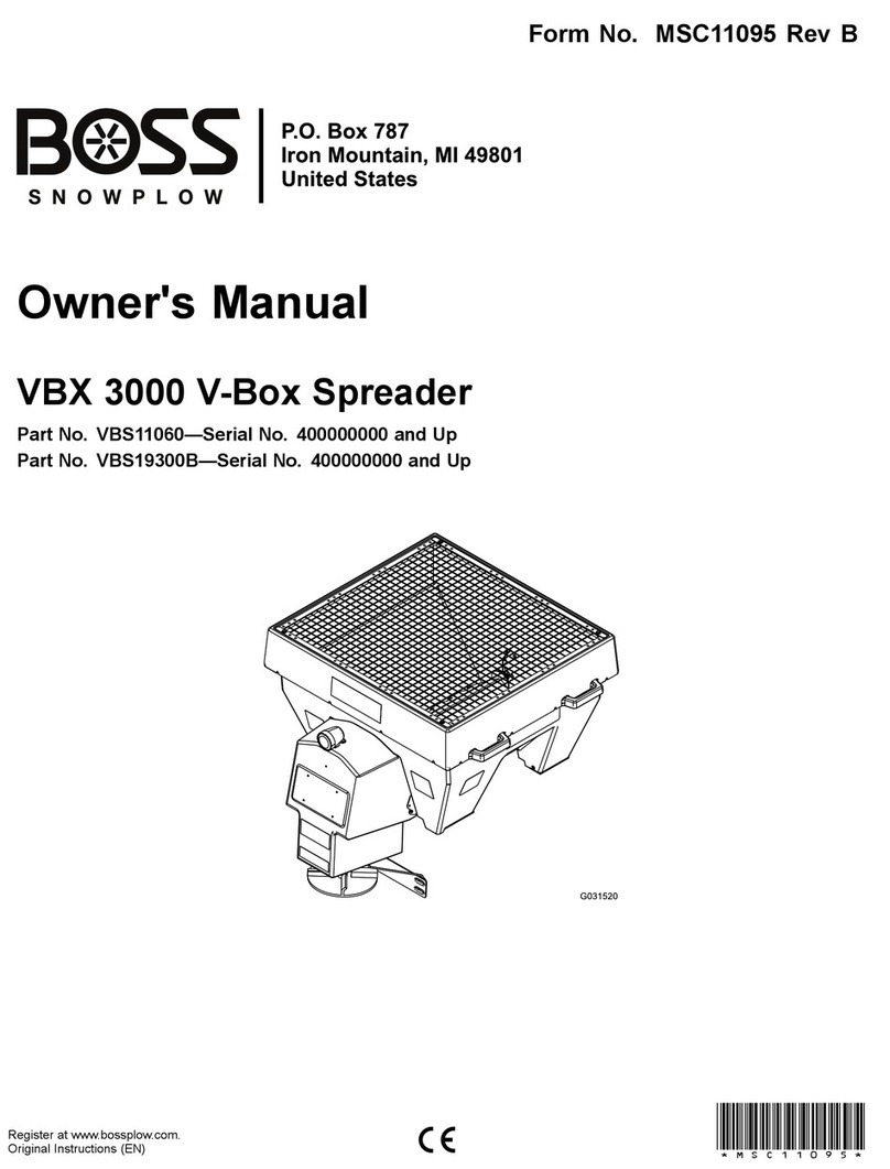
Boss Snowplow VBX 6500 User manual

FormNo.VBS14720RevA
Owner'sManual
VBX6500/8000/9000V-BoxSpreader
Registeratwww.bossplow.com.
OriginalInstructions(EN)*VBS14720*A

ThisproductcomplieswithallrelevantEuropean
directives;fordetails,pleaseseetheseparateproduct
specicDeclarationofConformity(DOC)sheet.
BOSSProductslimitedconsumerwarrantyandBOSS
Productscommercialwarrantypoliciesarelocatedat
www.bossplow.com.
Patentspending.
Introduction
Readthisinformationcarefullytolearnhowtooperate
andmaintainyourproductproperlyandtoavoid
injuryandproductdamage.Youareresponsiblefor
operatingtheproductproperlyandsafely.
YoumaycontactBOSSdirectlyatwww.bossplow.com
forproductsafetyandoperationtrainingmaterials,
accessoryinformation,helpndingadealer,orto
registeryourproduct.
Wheneveryouneedservice,genuineBOSSparts,or
additionalinformation,contactanAuthorizedBOSS
DealerorBOSSTechnicalService(1-800-286-4155)
andhavethemodelandserialnumbersofyour
productready.Figure1identiesthelocationofthe
modelandserialnumbersontheproduct.Writethe
numbersinthespaceprovided.
g029483
Figure1
1.Serialnumberlocation
ModelNo.
SerialNo.
Thismanualidentiespotentialhazardsandhas
safetymessagesidentiedbythesafety-alertsymbol
(Figure2),whichsignalsahazardthatmaycause
seriousinjuryordeathifyoudonotfollowthe
recommendedprecautions.
g000502
Figure2
1.Safety-alertsymbol
Thismanualuses2wordstohighlightinformation.
Importantcallsattentiontospecialmechanical
informationandNoteemphasizesgeneralinformation
worthyofspecialattention.
Contents
Safety.......................................................................3
Preparation.........................................................3
Operation............................................................3
SafetyandInstructionalDecals..........................4
Setup........................................................................7
InstallingtheWireHarness.................................7
MountingtheSpreader.......................................9
AdjustingtheSlideStop......................................9
InstallingtheTie-DownD-Rings........................10
BuildingandInstallingtheSpacer......................11
SecuringtheSpreader.......................................11
InstallingtheSpinnerAssembly.........................11
InstallingtheSpreaderController......................12
CheckingtheInstallation...................................12
ProductOverview...................................................13
Controls...........................................................13
SpreaderController.......................................14
Specications..................................................15
Attachments/Accessories.................................15
Operation................................................................16
AdjustingtheHeightoftheSpinner
Assembly......................................................16
LoadingtheSpreader.......................................16
OperatingtheSpreader....................................16
FreeingaClog..................................................17
AdjustingtheMaterialDeectors......................17
UnloadingtheSpreader....................................18
RemovingtheSpinnerAssembly......................18
InstallingthePintle-ChainRestrictorPlate
(Optional)......................................................19
OperatingTips.................................................19
Maintenance...........................................................20
RecommendedMaintenanceSchedule(s)...........20
Lubrication..........................................................20
GreasingtheMachine.......................................20
MiscellaneousMaintenance.................................20
AdjustingthePintle-ChainConveyor
Tension.........................................................20
ControllerStatusandErrorIndicators...............22
Cleaning..............................................................24
©2018—BOSSProducts
P .O.Box787
IronMountain,MI498012
Contactusatwww.bossplow.com.
PrintedintheUSA
AllRightsReserved

CleaningtheMachine.......................................24
Storage...................................................................24
Troubleshooting......................................................25
.........................................................................25
Safety
Improperuseormaintenancebytheoperatoror
ownercanresultininjury.Toreducethepotential
forinjury,complywiththesesafetyinstructions
andalwayspayattentiontothesafety-alert
symbol,whichmeans:Caution,Warning,or
Danger—personalsafetyinstruction.Failureto
complywiththeinstructionmayresultinpersonal
injuryordeath.
Preparation
•ReadtheOwner’sManualbeforeoperatingor
servicingthespreader.
•Ensurethatonlytrainedpersonnelinstallsand
performsmaintenanceontheequipment.
•Usea500kg(1/2ton)minimumliftingdeviceto
moveheavyspreadercomponents.Neverputany
partofyourbodyunderasuspendedload.
•Thisspreaderhasanoperatingsoundlevelbelow
70dBAwhileinsidethevehicle.Wearhearing
protectionwhileoperatingthespreaderoutside
ofthevehicle.
•Alwayswearappropriatepersonalprotective
equipmentwhenloading,unloading,andservicing
thespreader.Wearsubstantial,slip-resistant
footwear,cold-weatherclothing,hardhat,safety
glasses,anddustprotection.
•Neverdisable,remove,orrelocateanysensorsor
othercomponentsrelatedtotheoperationofthe
airbagsinyourvehicle.
Operation
•Neverputanypartofyourbodybetweenthe
spreaderandthevehicle.
•Whentransportingthespreader,ensurethatitis
properlysecured.Instructionsareavailableat
www.bossplow.com.
•Materialsafetydatasheets(MSDS)areavailable
atwww.bossplow.com.
•Donotoperatethemachinewhileill,tired,or
undertheinuenceofalcoholordrugs.
•Forvehiclemountedspreaders,alwaysfollow
themanufacturer’srecommendationsforproper
parkingprocedures.
•Alwayswearyourseatbeltwhileoperatingamotor
vehicle.
•Donotexceed22km/h(14mph)whilespreading.
•Donotexceed72km/h(45mph)whiletransporting
thespreader.
•Overloadingthespreadercouldresultin
anaccidentordamage.Neverexceedthe
gross-vehicle-weightrating(GVWR)orthefront
3

orreargross-axle-weightratings(FGAWRor
RGAWR)forthevehicle.
•Thisspreaderisrestrictedtotheuseofdry,
free-owingsalt,sand,andsand/saltmix.Donot
runothermaterialsthroughthespreader.
•Donotattempttomountorremovethespreader
withmaterialinit.
•Turnthevehicleandspreaderoffbeforelling,
mounting,removing,servicing,orcleaningit.
•Donotoperatethespreaderwithin7.6m(25ft)
ofbystanders.
•Donotclimbintoorrideonthespreader.
•Keepyourhands,feet,andclothingawayfrom
movingpartsandmountingpoints.
•Mountthespreadertoavehiclebeforeloading
material.
•Installratchetstrapsandkeepthemproperly
tightenedatalltimes.
•Donotstorematerialinthehopper.
SafetyandInstructionalDecals
Safetydecalsandinstructionsareeasilyvisibletotheoperatorandarelocatednearanyarea
ofpotentialdanger.Replaceanydecalthatisdamagedormissing.
decalmsc14031b
MSC14031
1.Warning—readtheOwner’sManual.6.Warning—donotstandorrideonthemachine.
2.Lossofcontrolhazard—donotoverllthemachine.7.Warning—stayawayfrommovingparts;keepallguardsand
shieldsinplace.
3.Warning—turnthemachineoffbeforelling.8.Warning—themachinemustbeinstalledbeforelling.
4.Warning—emptythehopperanddisconnectthepowerbefore
installingorremovingthemachine.
9.Warning—donotstorematerialsinthemachine.
5.Thrownobjecthazard—keepbystandersaway.10.Warning—turnthemachineoffanddisconnectthepower
beforeservicingthemachine.
4

decalmsc18131b
MSC18131
1.Crushinghazard—keephandsclear.
decalvbs14306b
VBS14306
1.Warning—donotstephere.
decalvbs14305b
VBS14305
1.Cutting/dismembermenthazard,spinner—keephands
clear.
decalvbs14307b
VBS14307
1.Finger/handentanglementhazard,pintlechain—keep
handsclear.
decalvbs14308b
VBS14308
1.Entanglementhazard,auger—keephandsclear.
5

decalvbs14567b
VBS14567
1.Lossofmachinehazard—theratchetstrapsmustbe
securedatalltimes.
decalvbs14568b
VBS14568
1.Dumpswitch
decalvbs14569b
VBS14569
1.Work-lightswitch
decalvbs14570b
VBS14570
1.Finger/handentanglement
hazard,pintlechain—keep
handsclear.
2.Entanglementhazard,
auger—keephandsclear.
6

Setup
InstallingtheWireHarness
DANGER
Vehicleenginescontainmovingpartsandcan
becomeextremelyhot,capableofcausing
severeburnsandseriousbodilyharm.
Shutofftheengineandallowitsufcienttime
tocooldownbeforeinstallingthiskit.
DANGER
Vehiclebatteriescancausedangerous
electricalshocksthatcouldleadtosevere
burnsordeath.
Disconnectyourbatterybeforeinstalling
thiskitbyremovingthenegativeconnector
followedbythepositiveconnector.
1.Securethevehicle-sidepower/groundandmain
harnessconnectorsnearthecenteroftherear
bumperusingcableties(Figure3).
2.Routethewireharnessalongthedriver-side
frame-railandintotheenginecompartment,and
secureitwithcableties.
Note:Keepthewireharnessawayfromany
hotormovingparts.
3.Insertthecontrollerconnectorthroughthe
rewallandintothevehiclecab,andsecureit
withcableties.
Note:Routetheconnectortothelocationthat
youwanttoinstallthecontroller.
4.Installthefuseblockwithin30cm(12inches)of
thebatteryandremovethefuse-blockcover.
5.Connecttheredpower/groundcabletothefuse
block(Figure3).
Note:Ensurethatthe150Afuseisinstalled.
6.Connectthepowercabletotheotherendofthe
fuseblock(Figure3).
7.Installthecoverontothefuseblock.
8.Connectthepowercabletothepositive(+)
batterypost(Figure3).
Important:Donotconnectthegroundcable
atthistime.
9.Connecttheredspadeconnectorwiththeinline
fusetoakeyedfusesourceonthevehicle
(Figure3).
10.Connecttheredspadeconnectorwithoutthe
inlinefusetothecenterhigh-mounted,stoplight
fuseifitisavailable(Figure3).
11.Connectthewhitebulletconnectortothe
reartail-lightgroundwireusingaquick-splice
connector(Figure3).
12.Connectthebrownbulletconnectortothe
rearrunning-lampwireusingaquick-splice
connector(Figure3).
13.Wrapalloftheexcesswireandsecureitinthe
enginecompartment.
14.Connecttheblackpower/groundcableand
thecontrollergroundcabletothenegative(–)
batterypost(Figure3).
7

g266761
Figure3
1.Controlmodule5.Vehicle-sidepower/ground
connector
9.Redspadeconnector13.Fuse(150A)
2.Spreader-sidemain
harness
6.Vehicle-sidemainharness
connector
10.Redspadeconnector(with
inlinefuse)
14.Fuseblock
3.Spreader-side
power/groundconnector
7.Whitebulletconnector11.Nuts(5/16inch)
4.Brownbulletconnector8.Controllerconnector12.Powercable
8

MountingtheSpreader
TheminimumtruckbedlengthfortheVBX6500is
1.68m(66inches),fortheVBX8000is2.0m(78
inches),andfortheVBX9000is2.3m(90inches).
1.Removethetailgatefromthevehicle.
2.Usingtheliftpoints(Figure4),liftthespreader
ontothetruckbedandsetitonthecenterline.
g265126
Figure4
1.Liftpoints
3.Slidethespreadertowardthevehiclecabuntil
theslidestophitsthetruckbed(Figure5).
Note:Thetruckbedmustbeatleast1.68m
(66inches)longfortheVBX6500,atleast2.0m
(78inches)longfortheVBX8000,andatleast
2.3m(90inches)longfortheVBX9000.
Note:Ifthespreaderisushwiththetruck
boxbuttheslidestopisnottouchingtherear
bumper,refertoAdjustingtheSlideStop(page
9).
g029486
Figure5
1.Slidestop
4.Drill4holes(7/16inch)intothetruckbedaligned
withtheslidestopholes.
5.Securetheslidestoptothevehicleusing4
bolts,4locknuts,and16atwashers(3/8inch).
Note:Slidestopfastenersarenotincluded.
6.Torquetheboltsto28N·m(19.7ft-lb).
AdjustingtheSlideStop
Optional
Youcanadjusttheslidestopofthespreader2.5cm
(1inch)or5cm(2inches)sothatthespreaderdoes
notextendpastthetruckbox.
1.Removeandretainthecarriageboltssecuring
theslidestop.
2.Slidethespreadersothatitdoesnotextend
pastthetruckboxandcontactthevehiclecab.
3.Movetheslidestoptothedesiredpositionand
secureitwiththepreviouslyremovedcarriage
bolts(Figure6).
9

g265127
Figure6
1.Slide-stopadjustment
holes
2.Slidestop
4.Torquetheboltsto28N·m(19.7ft-lb).
InstallingtheTie-Down
D-Rings
1.Usinga7/16-inchdrillbit,markanddrillthe
holesfortheD-ringsasshowninFigure7.
Note:Drilltheholesthroughorneartheframe
cross-membersofthevehicle.
g029488
Figure7
1.Backofthespreaderleg
totheD–ringcenter—3.8
cm(1–1/2inches)
2.D–ringcentertothe
D–ringcenter—129.5cm
(51inches)
2.InstalltheD-ringsasshowninFigure8and
torquetheboltsto28N·m(19.7ft-lb).
g029489
Figure8
1.Bolt(1–1/2inch)4.Bedmountplate
2.Flatwasher(3/8inch)5.Flatwasher(3/8inch)
3.D-ring6.Locknut
10

BuildingandInstallingthe
Spacer
1.Measurethedistancefromthefrontofthetruck
boxtothespreaderlegs.
2.Using3.8x18.4cm(1–1/2x7–1/4inch)lumber,
buildthespacerasshowninFigure9.
g036953
Figure9
1.Distancebetweenthe
spreaderlegandthetruck
box
3.57.7cm(22–3/4inches)
2.Distancebetweenthe
truckboxandthetake-up
housing
4.Widthofthetruckbox
3.Insertthespacerbetweenthespreaderandthe
frontofthetruckbox.
SecuringtheSpreader
DANGER
Thespreaderisheavyandcouldcause
seriousinjuryorpropertydamageifitfalls
offthevehicle.
Ensurethattheratchetstrapsaresecurely
attachedtothespreaderatalltimes.
1.ConnecttheratchetstrapstotheD-ringsaround
theupperedgeofthespreader(Figure10).
g029491
Figure10
1.D-ring2.Ratchetstraps
2.Crossthestrapsnearthevehiclecabandattach
themtotheD-ringsoppositetothemonthe
truckbed(Figure10).
3.Attachthestrapsneartherearofthevehicle
totheD-ringsnearestthemonthetruckbed
(Figure10).
4.Tightenthestrapsevenlytosecurethespreader.
InstallingtheSpinner
Assembly
1.Attachtheadjustmentassemblytothespinner
assemblyusing2atwashers(5/16inch)and
4thumbscrewsasshowninFigure11.Tighten
them1/4-turnpastnger-tight.
11

g029492
Figure11
1.Adjustmentassembly4.Spinnerassembly
2.Thumbscrew5.Cotterpin
3.Flatwasher(5/16inch)6.Latchpin
2.Removeandretainthelatchandcotterpins
fromthespinnerassembly(Figure11).
3.Attachthespinnerassemblytothespreaderand
secureitwiththepreviouslyremovedlatchand
cotterpins(Figure11).
Important:Thespinnerassemblyisheavy
andrequires2peopletolift.
4.Connectthewireharness.
InstallingtheSpreader
Controller
Mountthecontrollerinthecabwhereitdoesnot
interferewithvehicleoperationorvisibility.
Important:Donotmountthecontrollerina
locationthatvehicleoccupantscouldcontactit
duringacrash.
1.Attachthemountingbrackettothevehicle
usingeither2hookandloopfastenersor2
sheet-metalscrews(Figure12).
g029493
Figure12
1.Controllerdisplay5.Mountingbracket
2.Slidingbracket6.Pan-headscrews
3.Sheet-metalscrews7.Thumbnut
4.Carriagebolt
2.Connectthecontrollerdisplaytothesliding
bracketusing4pan-headscrews(Figure12).
3.Attachtheslidingbrackettothemounting
bracketusing2carriageboltsandthumbnuts
(Figure12).
Note:Positionthecontrollerscreensothatitis
clearlyvisibletothedriver.
4.Connectthewireharnesscontrollerconnector
tothecontrollerdisplay.
CheckingtheInstallation
1.FormodelsVBS14210B,VBS15310B,and
VBS15160B,checkthepintlechainconveyor
tension;refertoAdjustingthePintle-Chain
ConveyorTension(page20).
2.Checkthattheunittypelistedonthecontroller
displaymatchesyourmachinetype;refertothe
MainScreen(page14)section.
Note:Iftheunittypedoesnotmatchyour
machine,contactyourAuthorizedBOSSDealer
aboutadjustingthecontrolmodule.
12

ProductOverview
g265128
Figure13
1.Hoppercover5.Dumpswitch
2.Materialdeector6.Pintle-chaintensionadjustment
3.Spinner-heightadjustment7.Backcover
4.Frontcover8.Work-lightswitch
Controls
Becomefamiliarwithallthecontrolsbeforeyou
operatethespreader.
MaterialDeector
Thematerialdeectorcontrolsthespreadofmaterials;
youcanadjustthecontrolstoprovidedifferentspread
patterns;refertoAdjustingtheMaterialDeectors
(page17).
DumpSwitch
Thedumpswitchactivatesthespreaderandempties
outthecontents.Pressandholdtheswitchtoempty
thespreader.
CAUTION
Whenoutsideofthevehiclecab,thismachine
producessoundlevelsthatcancausehearing
lossthroughextendedperiodsofexposure.
Wearhearingprotectionwhileoperatingthe
dumpswitch.
13

Work-LightSwitch
Thework-lightswitchactivatestherearlights.
ControlModule
Thecontrolmoduleislocatedunderthefrontcover.
TheLEDonthemodulecanbeusedtohelpwith
Troubleshooting(page25).
g266146
Figure14
1.Controlmodule
SpreaderController
Thespreadercontrollershowsinformationaboutyour
machine.Figure15andFigure16illustratethemain
screenandadjustmentscreenofthecontroller.You
canswitchbetweenthemainscreenandadjustment
screenatanytimebypressingtheModebutton.
RefertoControllerStatusandErrorIndicators(page
22)foradditionalcontrollericons.
MainScreen
g029495
Figure15
1.Feedspeeddial5.Vibratebutton
2.Start/Stopbutton6.Blastbutton
3.Modebutton7.Lightbutton
4.SpinnerSpeeddial
•FeedSpeeddial—increasesthefeedmotorspeed
whenturnedclockwise,anddecreasesthefeed
motorspeedwhenturnedcounterclockwise.The
feedspeeddetermineshowquicklymaterialis
pulledfromthehopper.
•Feederdisplay—indicatesthefeedmotorspeed
•Start/Stopbutton—turnsthefeeder,spinner,and
vibrator(ifactive)motorsonoroff
•Unittypedisplay—indicatesifthecontrolmodule
issetforaugerorpintlechainmode
•Modebutton—switchesbetweenthemainscreen
andtheadjustmentscreen
•Spinnerdisplay—indicatesthespinnermotor
speed
•SpinnerSpeeddial—increasesthespinner
motorspeedwhenturnedclockwise,and
decreasesthespinnermotorspeedwhenturned
counterclockwise.Thespinnerspeeddetermines
howfarthematerialisthrown.
•Lightbutton—turnstherearlightsonoroff
•Blastbutton—momentarilysendsfullpowerto
thefeedandspinnermotorsin2secondbursts.
Holdingthebuttonincreasesthemotorstofull
speedfor2secondsandthenpausesfor2
secondsthenrepeatsuntilyoureleasethebutton.
TheBlastbuttononlyworksifthefeedandspinner
motorsaresetatlessthanmaximumspeed.
•Vibratebutton—switchesthevibratoronoroff
Note:Thevibratoronlyrunswhenthefeeder
motorison.
14

AdjustmentScreen
g029496
Figure16
1.Beeperbutton4.DisplayAdjustmentbutton
2.Modebutton5.LightAdjustmentbutton
3.VibratorAdjustmentbutton
•Beeperbutton—turnsthebeepersoundonoroff
•Modebutton—switchesbetweenthemainscreen
andtheadjustmentscreen
•Batteryvoltagedisplay—indicatestheestimated
voltageofthevehicle
•LightAdjustmentbutton—adjuststherearlight
brightnesslevelfrom1to4
•DisplayAdjustmentbutton—adjuststhedisplay
screenbrightnessfrom1to4
•VibratorAdjustmentbutton—adjuststhevibration
levelfrom1to4
Specications
Note:Specicationsanddesignaresubjecttochangewithoutnotice.
VBX6500VBX8000VBX9000
Length2.4m(94inches)2.9m(115inches)3.1m(123inches)
Hopperheight97cm(38inches)97cm(38inches)124.5cm(49inches)
Hopperwidth124.5cm(49inches)123cm(48–1/4inches)122cm(48inches)
Weight(empty)250kg(550lb)withauger;
272kg(600lb)withpintlechain
272kg(600lb)withauger;
295kg(650lb)withpintlechain
322kg(710lb)withauger;
345kg(760lb)withpintlechain
Capacity1.2m3(1.5yd3)1.5m3(2yd3)2.3m3(3yd3)
Attachments/Accessories
AselectionofBOSSapprovedattachmentsand
accessoriesisavailableforusewiththemachine
toenhanceandexpanditscapabilities.Contact
yourAuthorizedServiceDealerorauthorizedBOSS
distributororgotowww.bossplow.comforalistofall
approvedattachmentsandaccessories.
Toensureoptimumperformanceandcontinuedsafety
certicationofthemachine,useonlygenuineBOSS
replacementpartsandaccessories.Replacement
partsandaccessoriesmadebyothermanufacturers
couldbedangerous,andsuchusecouldvoidthe
productwarranty.
15

Operation
Note:Determinetheleftandrightsidesofthemachinefromthenormaloperatingposition.
AdjustingtheHeightofthe
SpinnerAssembly
Youcanadjustthespinnerassemblyheightin5cm(2
inch)incrementsupto20cm(8inches)toaccountfor
vehicleswithhigherbeds.Thebottomofthespinner
assemblyshouldbeapproximately61cm(24inches)
fromtheground.
1.Removethe2upperthumbscrews(Figure17).
g029497
Figure17
2.Holdtheassemblyandloosenthe2lower
thumbscrews.
3.Slidethespinnerassemblydowntothedesired
height.
4.Insertthe2upperthumbscrewsandtighten
them.
5.Tightenthe2lowerthumbscrews.
LoadingtheSpreader
Important:Onlyusedrysalt,sand,sand/salt,or
cinder/saltmixesinthespreader.Othermaterials
couldcausedamagetothemachine.
Thedensityofmaterialsthatcanbeloadedintothe
spreadervariesandthereforesowilltheamountof
agivenmaterialthatcanbecarriedbythespreader
beforethemaximumloadratingisreached.
Important:Whenllingthespreader,donot
exceedthegross-vehicle-weightrating(GVWR)or
gross-axle-weightrating(GAWR).
1.Ensurethatthespreaderissecurelymountedto
thevehicleandthatthetopscreenisinstalled
andclosed.
2.Removethetarp.
3.Determinetheamountofmaterialthatyoucan
safelytransportusingtheGVWR/GAWRofthe
vehicleandthefollowingtable.
MaterialTypeWeightRange
Finesalt1,121to1,281kg/m3(1,890to
2,160lb/yd3)
Coarsesalt721to961kg/m3(1,215to
1,620lb/yd3)
Coarsesand(dry)1,442to1,762kg/m3(2,430to
2,970lb/yd3)
Coarsesand(wet)1,762to2,082kg/m3(2,970to
3,510lb/yd3)
Cinders641kg/m3(1,080lb/yd3)
4.Fillthespreaderevenlywiththematerial,making
surenottollpastthetopofthehopper.
Important:Overllingthehoppercould
damagethespreaderandthevehicle.
OperatingtheSpreader
DANGER
Hands,feet,andclothingcangetcaughtin
themovingpartsofthespreaderandcause
seriousbodilyinjuryandlossoflimbs.
Keepyourhands,feet,andclothingaway
fromthemovingspinner,auger,chain,and
attachmentpoints.
CAUTION
Thespreaderthrowsmaterialatahighspeed
thatcouldcauseminorinjuriestobystanders.
Bystandersshouldstayaminimumof7.6m
(25ft)awayfromoperatingspreaders.
1.Startthevehicle.
Note:Thecontrollerdisplayshouldlightup
whenyoustartthevehicle.
16

2.Usethecontrollertosetthedesiredfeedspeed
andspinnerspeed.
Note:Youcanadjustthefeedandspinner
speedswhilethespreaderisoperating.
3.Ifyouplantousethevibratorduringspreading,
turnitonnow.
Note:Thevibratordoesnotstartuntilyoustart
thefeedmotor.
4.PresstheSTART/STOPbuttontoactivatethe
spreader.
Note:Alwayscheckforbystandersbefore
startingthespreader.
5.Whilespreading,youcanpresstheBLASTbutton
tomomentarilyincreasethespeedofthefeed
andspinnermotors.
6.PresstheSTART/STOPbuttonwhenyouare
nishedspreadingtostopthespreader.
7.Emptytheleftovermaterialsfromthespreader;
refertoUnloadingtheSpreader(page18).
FreeingaClog
ThewordJAMwillappearineitherthefeederor
spinnerdisplaywhendebrisgetswedgedintheauger
orpintlechain,orunderthespinnerdisk.
1.Donotturnoffthemachinewhenajamrst
occurs.
Note:Thespreaderisdesignedtoautomatically
freeclogs.
2.IfJAMSTUCKappearsinthefeederorspinner
display,pushtheStart/Stopbutton.
Note:Ifthemachinedoesnotcleartheclog
afterseveralattempts,themotorgoesintoa
cooldownmodefor3minutes.
3.Iftheclogisnotclearedautomatically,
disconnectthespreaderwireharnessand
manuallyfreetheclog.
WARNING
Movingpartsonthespreadercan
entanglehandsandcutordismember
ngers.
•Disconnectthespreaderwireharness
beforeattemptingtomanuallyfreea
clog.
•Ifthetopscreenisopened,ensure
thatallboltsaresecuredafterfreeing
theclog.
AdjustingtheMaterial
Deectors
Youcanadjustthematerialdeectorsbyinsertingthe
deectorpinsintothestaggeredholesaroundthe
spinner(Figure18).
g029498
Figure18
1.Materialdeector2.Adjustmentholes
Youcanadjustthespreadpatternbypositioningthe
deectorsasshowninFigure19.
g029499
Figure19
DeectionSettings
1.Driversideopen3.Bothsidesopen
2.Passengersideopen
17

UnloadingtheSpreader
Important:Donotleavematerialinthehopperas
itcoulddamagethemachine.
1.Positionthespreaderintheareawhereyou
wanttodepositthematerial.
2.Unplugthespinnerharnessfromthemainwire
harness.
3.Removetheleftlatchandcotterpinfromthe
spinnerassembly(Figure20).
g029500
Figure20
1.Latchandcotterpin
4.Swingthespinnerassemblyfreefromthe
hopperopening(Figure20).
Note:Donotmovethevehiclewhenthe
spinnerassemblyisswungout.
5.Pushandholdthedumpswitchtounloadthe
hoppermaterial.
CAUTION
Thespreaderthrowsmaterialatahigh
speedthatcouldcauseminorinjuries.
Standtothesideofthespreaderwhen
activatingthedumpswitch.
6.Swingthespinnerassemblybackintoplace
andsecureitwiththepreviouslyremoved
attachmentpinandcotterpin.
7.Connectthespinnerharnesstothemainwire
harness.
RemovingtheSpinner
Assembly
1.Positionthespreaderoveraat,drysurface.
2.Unplugthespinnerharnessfromthemainwire
harness.
3.Removethe2latchandcotterpinssecuringthe
spinnerassemblytothehopper(Figure21).
g265081
Figure21
1.Latchpin3.Spinnerassembly
2.Cotterpin
4.Removethespinnerassembly.
DANGER
Thespinnerassemblyisheavyandcould
causeseriousinjuryifdropped.
Ensurethatyourfootingisstable,and
avoidremovingthespinnerassembly
nearslipperyorunevensurfaces.
5.Inserttheattachmentpinsandcotterpinsinto
thespinnerassemblyforstorage.
18

InstallingthePintle-Chain
RestrictorPlate(Optional)
Pintle-ChainModelsOnly
Ifthespreaderowistoofast,installtherestrictor
plate.Ifthespreaderowistooslow,removethe
restrictorplate.
1.Unplugthepower/groundcableandthemain
harnessfromthewireharness.
2.Removethespinnerassembly;referto
RemovingtheSpinnerAssembly(page18).
3.Removetheplasticclipssecuringthefrontcover
tothehopper(Figure22).
g029502
Figure22
1.Plasticclip2.Frontcover
4.Carefullypullthecoverawayandunplugthe
coverharnessfromthemainwireharness.
5.Setthecoveraside.
6.Inserttherestrictorplateandsecureitwith2
boltsandlocknuts(Figure23).
g266857
Figure23
1.Restrictorplate
7.Positionthefrontcoverinplaceandconnectthe
coverharnesstothemainwireharness.
8.Securethefrontcovertothehopperusingthe
previouslyremovedplasticclips.
9.Connectthepower/groundcableandmain
harnesstothewireharness.
OperatingTips
•Knowtheareainwhichyouareworking;hidden
obstructionssuchascurbs,sidewalks,andpipes
candamagethespreaderorvehicle.
•Donotlettheicebuildup;alwaysstartassoon
aspossible.
•Alwayswearyourseatbeltwhenspreading.
•Alwaysremembertospreadatasafespeed.
•Neverrideonorputbodypartsintothespreader
whileservicingoroperatingit.
19

Maintenance
WARNING
Failuretoproperlymaintainthemachinecouldresultinprematurefailureofmachinesystems
causingpossibleharmtoyouorbystanders.
Keepthemachinewellmaintainedandingoodworkingorderasindicatedintheseinstructions.
CAUTION
Ifyouleavethekeyintheswitch,someonecouldaccidentlystarttheengineandseriously
injureyouorotherbystanders.
Removethekeyfromtheswitchbeforeyouperformanymaintenance.
Note:Determinetheleftandrightsidesofthemachinefromthenormaloperatingposition.
RecommendedMaintenanceSchedule(s)
MaintenanceService
IntervalMaintenanceProcedure
Beforeeachuseordaily
•Checktheratchetstrapsandtightenasnecessary.
•Checkthepintle-chainconveyortension.
•Emptythecleanouttray.
Every20hours
•Greasethebearings.
•Greasethepintlechain(ModelVBS14210B,VBS15310B,andVBS15160Bonly).
•Tightenthehardware.
Beforestorage
•Unloadthespreader.
•Cleanandgreaseallofthebearings.
•Cleanandgreasethepintle-chain(ModelVBS14210BandVBS15310Bonly).
Lubrication
GreasingtheMachine
Every20hours—Greasethebearings.
Every20hours—Greasethepintlechain(Model
VBS14210B,VBS15310B,andVBS15160B
only).
Greaseallofthebearings,andpintlechainformodel
VBS14210B,VBS15310B,andVBS15160B,witha
general-purpose,lithium-basedgrease.
Miscellaneous
Maintenance
AdjustingthePintle-Chain
ConveyorTension
Pintle-ChainModelsOnly
ServiceInterval:Beforeeachuseordaily—Check
thepintle-chainconveyortension.
1.Disconnectthepower/groundcableandmain
harnessfromthewireharness.
2.RemovethebackcovershowninFigure24.
20
This manual suits for next models
2
Table of contents
Other Boss Snowplow Spreader manuals

Boss Snowplow
Boss Snowplow VBX 3000 User manual

Boss Snowplow
Boss Snowplow WBS28080 User manual

Boss Snowplow
Boss Snowplow TGS 800 User manual

Boss Snowplow
Boss Snowplow SNR24030 User manual

Boss Snowplow
Boss Snowplow TGS 600 User manual

Boss Snowplow
Boss Snowplow WBS15852 User manual

Boss Snowplow
Boss Snowplow TGS 300 User manual

Boss Snowplow
Boss Snowplow MSC22875B User manual

Boss Snowplow
Boss Snowplow TGS 300 Series User manual

Boss Snowplow
Boss Snowplow TGS 800 User manual