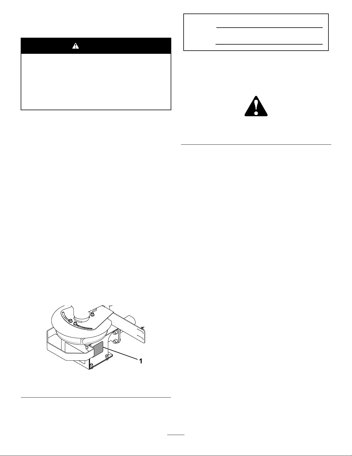
Safety
Improperlyusingandmaintainingtheequipment
canresultininjury.Toreducethepotentialfor
injury,complywiththesesafetyinstructions
andalwayspayattentiontothesafety-alert
symbol,whichmeans:Caution,Warning,or
Danger—personalsafetyinstruction.Failureto
complywiththeinstructionmayresultinpersonal
injuryordeath.
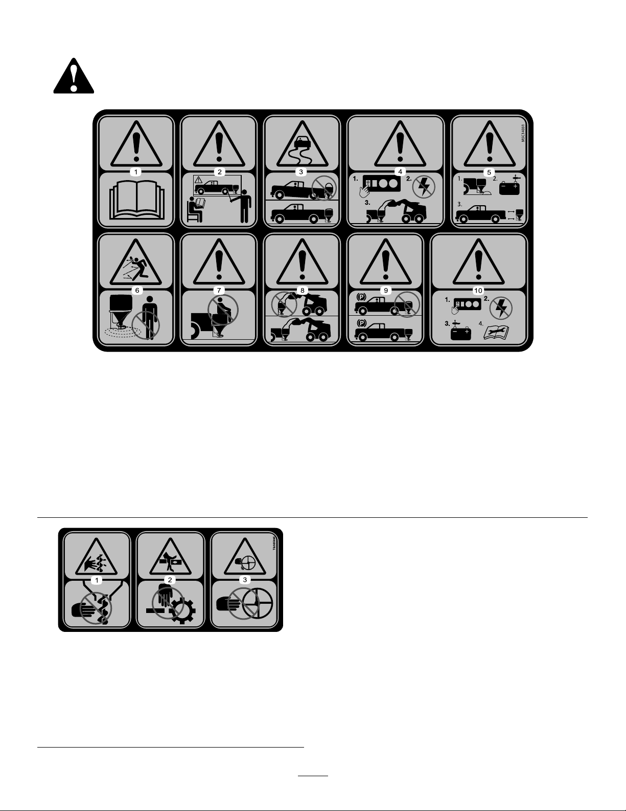
Preparation
•ReadtheOwner’sManualbeforeoperatingor
servicingthespreader.
•Ensurethatonlytrainedpersonnelinstallsand
performsmaintenanceontheequipment.
•Alwayswearappropriatepersonalprotective
equipmentwhenloading,unloading,andservicing
thespreader.Wearsubstantial,slip-resistant
footwear,cold-weatherclothing,hardhat,safety
glasses,anddustprotection.
•Manynewertrucksareequippedwithairbags.
Neverdisable,remove,orrelocateanysensorsor
othercomponentsrelatedtotheoperationofthe
airbags.
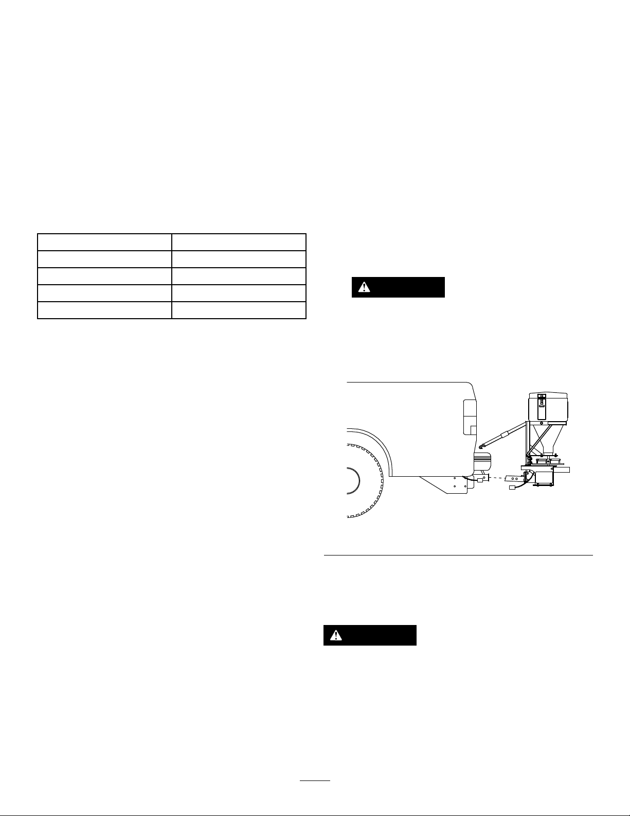
•TGS300spreadersmustonlybeusedwitha
minimumClassIIreceiverhitch.Donotexceed
thevehiclehitchrating.
•TheTGS300canholdamaximumweightof91
kg(200lb)ofsalt.Donotexceedthisweight.
Operation
•ReadtheOwner’sManualbeforeoperatingor
servicingthespreader.
•Donotoperatethemachinewhileill,tired,or
undertheinuenceofalcoholordrugs.
•Forvehicle-mountedspreaders,alwaysfollow
themanufacturer’srecommendationsforproper
parkingprocedures.
•Alwayswearyourseatbeltwhileoperatingamotor
vehicle.
•Donotexceed22.5km/h(14mph)while
spreading.
•Thisspreaderhasanoperatingsoundlevelbelow
70dBA.
•Neverputanypartofyourbodybetweenthe
spreaderandthevehicle.
•Overloadingthespreadercouldresultin
anaccidentordamage.Neverexceedthe
gross-vehicle-weightrating(GVWR)orthefront
orreargross-axle-weightratings(FGAWRor
RGAWR)forthevehicle.
•Thisspreaderisrestrictedtotheuseofsaltonly.
Donotrunothermaterialsthroughthespreader.
•Donotattempttomountorremovethespreader
withmaterialinit.
•Turnthespreaderoffbeforelling,mounting,
removing,servicing,orcleaningit.
•Neveroperatethespreaderwithin7.6m(25ft)
ofbystanders.
•Donotclimbintoorrideonthespreader.
•Keepyourhands,feet,andclothingawayfrom
movingpartsandmountingpoints.
•Mountthespreadertoavehiclebeforeloading
material.
•Installratchetstrapsandkeepthemproperly
tightenedwiththeslide-inattachment.
•Whentransportingthespreader,ensurethatitis
properlysecured.Instructionsareavailableat
www.bossplow.com.
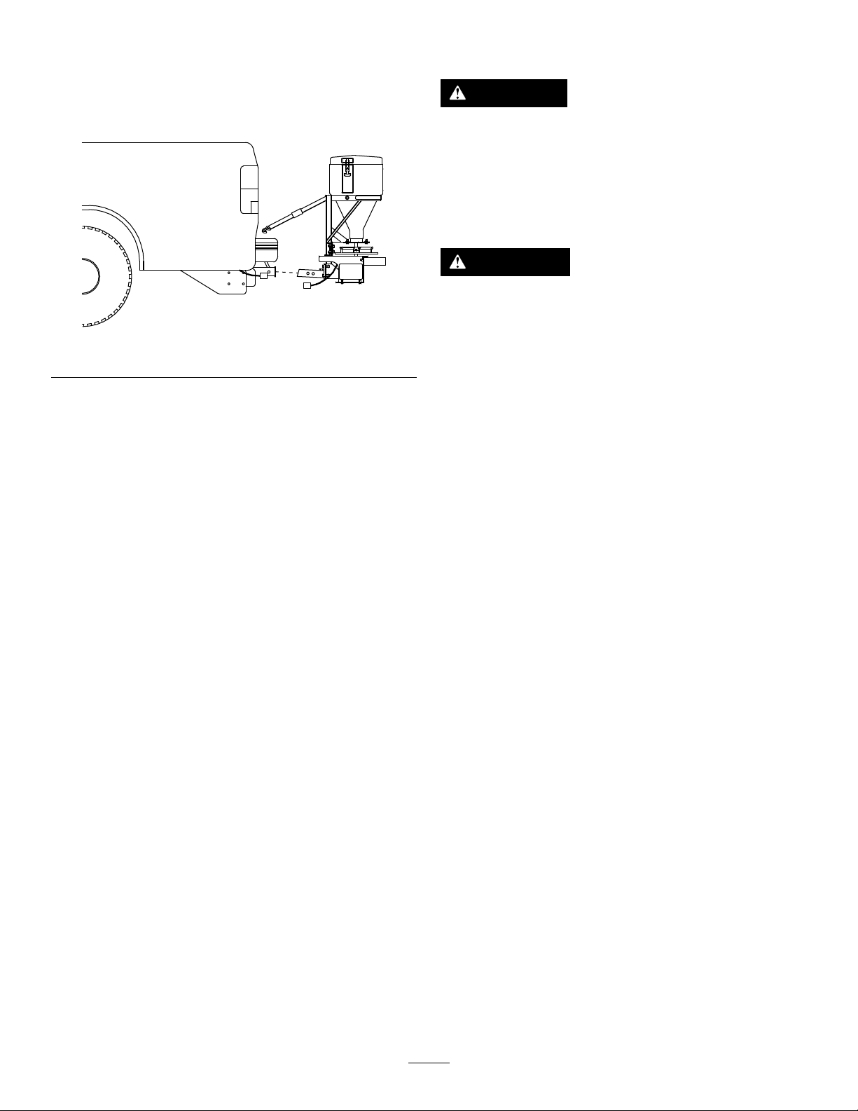
•Theslide-inattachmentmustbefullyengagedand
pinnedintothevehicle’s3cm(1-1/4inch)or5cm
(2inch)receiverhitch.
•Materialsafetydatasheets(MSDS)areavailable
atwww.bossplow.com.
•Usea1/2tonminimumliftingdevicetomove
heavyspreadercomponents.
•Donotstorematerialinthehopper.
3