BOSSCO BCONDP User manual

1
BOILER CONDENSATE PUMP - INSTALLATION INSTRUCTIONS
Product Keyword: BCONDP
INTRODUCTION
Your BOSS Condensate Pump is designed as an automatic condensate removal pump for pumping away
room temperature condensate from domestic and light commercial condensing boilers. The pump is controlled
by a float/switch mechanism which turns the pump on to discharge the water when approximately 60mm of
condensate collects in a tank. The pump automatically switches off when the tank drains to approximately
30mm.
The BOSS Condensate Pump you have purchased is a high quality product that has been engineered to give
you long and trouble-free service.
This pump is carefully packaged, inspected and tested to ensure safe operation and delivery. When you
receive the pump, examine it carefully to determine there are no broken or damaged parts that may have
occurred during shipment. If damage has occurred, please contact your supplier. They will assist you in
replacement or repair, if required.
READ INSTRUCTIONS CAREFULLY BEFORE ATTEMPTING TO INSTALL, OPERATE OR SERVICE THE
BCONDP PUMP. KNOW THE PUMP APPLICATION, LIMITATIONS AND POTENTIAL HAZARDS. PROTECT
YOURSELF AND OTHERS BY OBSERVING ALL SAFETY INFORMATION. FAILURE TO COMPLY WITH
INSTRUCTIONS COULD RESULT IN PERSONAL INJURY AND/OR PROPERTY DAMAGE! RETAIN
INSTRUCTIONS FOR FUTURE REFERENCE. INSTALLATION AND CONNECTIONS ARE TO BE MADE BY
A QUALIFIED PERSON.
SAFETY GUIDELINES
DO NOT USE TO PUMP FLAMMABLE OR EXPLOSIVE FLUIDS SUCH AS PETROL, FUEL OIL,
KEROSENE, ETC. DO NOT USE IN EXPLOSIVE ATMOSPHERES. PUMP SHOULD BE USED WITH
LIQUIDS COMPATIBLE WITH PUMP COMPONENT MATERIALS.
DO NOT HANDLE PUMP WITH WET HANDS OR WHEN STANDING ON WET OR DAMP SURFACE, OR IN
WATER. THIS PUMP IS SUPPLIED WITH A GROUNDING CONDUCTOR AND/OR GROUNDING TYPE
ATTACHMENT PLUG. TO REDUCE THE RISK OF ELECTRICAL SHOCK, BE CERTAIN THAT IT IS
CONNECTED TO A PERMANENT EARTH.
FOR INSTALLATIONS WHERE PROPERTY DAMAGE AND/OR PERSONAL INJURY MIGHT RESULT
FROM AN INOPERATIVE OR LEAKING PUMP DUE TO POWER CUTS, DISCHARGE LINE BLOCKAGE,
OR ANY OTHER REASON, A BACKUP SYSTEM(S) AND/OR ALARM SHOULD BE USED.
SUPPORT PUMP AND PIPING WHEN ASSEMBLING AND WHEN INSTALLED. FAILURE TO DO SO MAY
CAUSE PIPING TO BREAK, PUMP TO FAIL, MOTOR BEARING FAILURES, ETC.
THE PUMP IS DESIGNED TO TAKE CONDENSATE ONLY, UNDER NO CIRCUMSTANCES SHOULD HIGH
TEMPERATURE PRESSURE RELIEF BE DISCHARGED INTO THE PUMP –(ALTERNATIVE THE
“BCONDPHWHOSE”PUMP IS SPECIFICALLY DESIGNED FOR THIS APPLICATION)
2
INSTALLATION
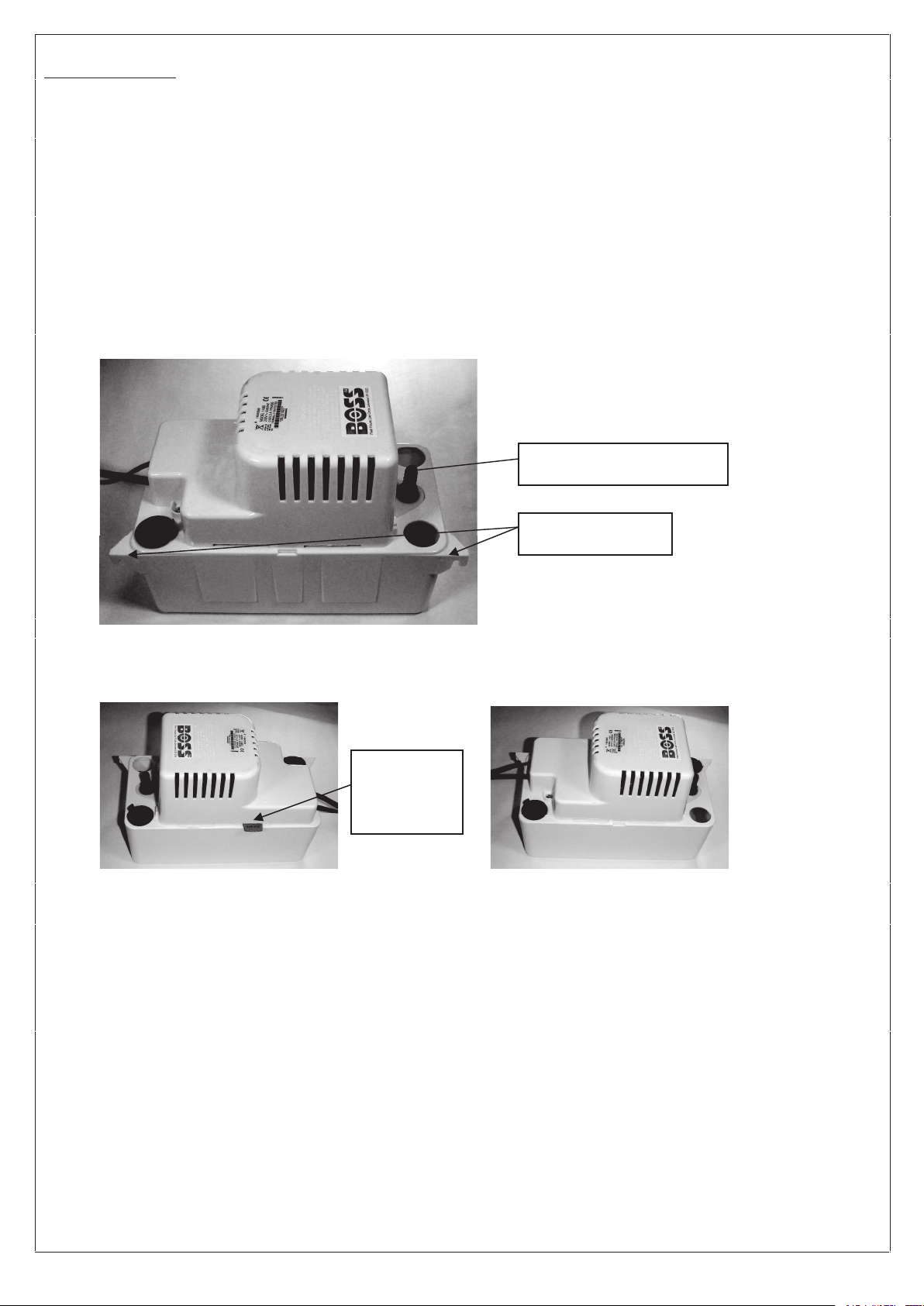
1. Mounting the pump: The tank has two slots provided to mount the unit on a vertical surface such as an
adjacent wall. The slots are located on the ends of the tank (Fig. 1). Pump must be level and the inlet must
be below the boiler drain point.
2. Carefully unpack the pump. Remove the cardboard packing from the motor cover air slots. Carefully slide
the packing strip away from the pump. This packing is used to prevent switch movement during shipment
(Fig. 2).
3. The pump should not be installed in a manner that will subject it to splashing or spraying.
4. The pump can be mounted in a Left Hand or Right Hand orientation allowing for cabling to the left or right
(Fig 2.)
Figure 1.
Figure 2.
Left Hand Orientation Right Hand Orientation
(wiring to right outlet hose to left) (wiring to left outlet hose to right)
Mounting Slots
Non Return Valve
Remove
Packing
Strip

3
ELECTRICAL CONNECTIONS
1. Shut off electrical power at fuse box before making any connections. All wiring must comply with local
codes.
2. Line voltage: Connect pump to voltage specified on label located on pump. Wiring is as follows:
Live - Brown
Neutral - Blue
Earth - Yellow/Green
3. If fused plug is used, a 1.0 amp fuse is recommended.
4. High level float switch connection options. The pump is fitted with a secondary float which will trigger a micro
switch just before the pump starts to over spill. This switch can be used to either switch off the boiler or signal
an external alarm (visual or audible alarms are available as option extras). The following diagrams show how
the high level float switch can be connected. (Fig 3 and Fig 4).
It is strongly recommended that either of these options is selected, if the pump where ever to over spill
the dilute acid condensate could cause damage to property.
Figure 3. Boiler Connection to high level float Figure 4. Alarm Connection to high level float
Switch switch
L
N
L
L
N N
E
EE
NO COM NC
3
2
1
4
3
2
1
1
22
1
33
Condensate Pump Boiler Connector
Fused Spur/Socket
Junction
Box
BR
BL
G/Y
Bk
Bk
L
N
L
L
N N
E
EE
NO COM NC
3
2
1
4
3
2
1
1
22
1
33
Condensate Pump Boiler Connector
Fused Spur/Socket
Junction
Box
BR
BL
G/Y
Bk
Bk
L
N
L
L
N N
E
EE
NO NC COM
3
2
1
3
2
1
1
22
1
33
Condensate Pump Boiler Connector
Fused Spur/Socket
BR
BL
G/Y
Bk Bk
Junction
Box
Audible Alarm
L
N
L
L
N N
E
EE
NO NC COM
3
2
1
3
2
1
1
22
1
33
Condensate Pump Boiler Connector
Fused Spur/Socket
BR
BL
G/Y
Bk Bk
Junction
Box
Audible Alarm
WATER DRAIN CONNECTIONS
Inlet Water Connections
1. Position pump beneath boiler condensate drain so that condensate flows into the pump inlet freely (use any
of the three openings provided).
2. The pump will accept up to three drain lines, although care should be used to make certain that total inflow
does not exceed outflow of pump. If more drains into the pump than the rated output of the pump, tank may
overflow.
3. Keep plugs in unused pump inlet openings to prevent debris from falling into the pump tank.
Outlet Water Connections
1. Connect the supplied 3/8" I.D. tubing to the non return valve (Fig 1). For best results, secure tubing with
clamps (not provided) but do not pinch collapse or otherwise restrict the tubing.
2. The pump is supplied with an adaptor which can be connected to standard 22mm pipe or with associated
adaptors (not supplied) to 32mm and 40mm pipe.
3. Tubing should rise vertically but not exceed the maximum shut off head (pumping height) of 4.3 metre above
the pump.
4. At highest point angle tubing horizontally and create a downward slope to the drainage point. Do not sharply
bend or twist the tubing in a way that might result in collapse or restriction of the tubing. Creating a downward
slope will allow the condensate to drain by gravity and keep tubing empty.
5. If it is not possible to create a downward slope, try to create an inverted “U”trap directly above the pump at
the highest point.

4
6. If routing in loft, basement or other area where the condensate hose could be exposed to freezing
conditions, hose should be insulated or changed for pre insulated version.
COMMISSIONING & MAINTENANCE
1. Before servicing the pump, disconnect the electric power at the fuse box.
2. Upon commissioning, check for debris in the drain pan. Remove any material that might block the drain line
or drain into the pump tank.
3. It is recommended that the pump be checked every six to twelve months for proper operation. Most
important is to check for debris blocking the pump discharge adapter/check valve. Check for proper free
movement of pump float (Fig 5).
4. Clean the holding tank and float with warm water and mild soap. Rinse completely when finished.
5. Check the inlet and outlet piping. Clean as necessary. Be sure there are no kinks in the outlet line that would
inhibit or restrict flow.
Figure 5.
TESTING
1. Turn on power
2. Lift the motor/tank cover assembly off the tank and hold level.
3. Test motor switch by raising main float with finger (Fig 5). Motor should turn on just before float contacts
underside of cover.
4. Replace motor/tank cover assembly on tank. This pump is designed for use with condensing boilers.
Caution must be taken to ensure acidity of condensate does not increase below the average pH of 3.4 (to
prevent localised pockets of acid that acts like a battery causing pitting) by routinely cleaning or flushing tank
with fresh water.
The BSS Group PLC
Fleet House
Lee Circle
Leicester LE13 3QQ
www.ptsplumbing.co.uk
Registered no: 60987 England *BOSS is a registered trademark of the BSS Group PLC
Little Giant Product Code: 53030478
Main Float
Table of contents
Popular Boiler Supplies manuals by other brands

GESTRA
GESTRA SRL 63-a Original Installation Instructions

Siemens
Siemens AGU2.522 Series Mounting instructions

Centrometal
Centrometal Cm Pelet-set 90 Technical instructions

Xylem
Xylem McDonnell & Miller GuardDog 751P Series instruction manual

Bosch
Bosch Condens 8300i W installation instructions

IDEAL
IDEAL EXRKIT07 instructions

Watts
Watts tekmar 294EXP Installation, operation and maintenance manual

oventrop
oventrop Regumat RTA-130 Installation and operating instructions

Immergas
Immergas 3.031186 Instruction and warning book

Daalderop
Daalderop Combi Assembly instructions

Bryan Boilers
Bryan Boilers LDTV-10 Specification sheet

Webstone
Webstone Hydro-Core user guide


