GESTRA SRL 63-a User manual

1
EN
English
Logic Unit
SRL 63-a
Original Installation Instructions
818588-04

2
Contents
Important Notes
Usage for the intended purpose ..............................................................................................................4
Safety note .............................................................................................................................................4
Danger ...................................................................................................................................................4
LV (Low Voltage) Directive and EMC Electromagnetic Compatibility) ........................................................4
ATEX (Atmosphère Explosible).................................................................................................................4
Note on the Declaration of Conformity / Declaration by the Manufacturer ..........................................4
Explanatory Notes
Scope of supply......................................................................................................................................5
Description .............................................................................................................................................5
Function .............................................................................................................................................5, 6
Note .......................................................................................................................................................6
Page
Installation
Installing the logic unit SRL 63-a ............................................................................................................9
Electrical Connection
Connecting the terminal strips .............................................................................................................10
Note .....................................................................................................................................................10
Attention ..............................................................................................................................................10
Tools ....................................................................................................................................................10
Wiring diagram of logic unit for monitoring SRL 63-a ...........................................................................11
SRL 63-a ................................................................................................................................................7
Name plate / marking .............................................................................................................................8
Dimensions.............................................................................................................................................8
Technical Data
Basic Setting
Factory setting......................................................................................................................................12
Functional Elements
SRL 63-a ...............................................................................................................................................9
Start-up, Operation, Alarms and Testing
SRL 63-a ......................................................................................................................................12 – 14
Danger .................................................................................................................................................14

3
Decommissioning
SRL 63-a ..............................................................................................................................................15
Contents – continued –
Page
Troubleshooting
Fault finding list ...................................................................................................................................15
Disposal
SRL 63-a ..............................................................................................................................................15

4
Important Notes
Safety note
The equipment fulfils a safety function and must only be installed and commissioned by qualified and
competent staff.
Retrofitting and maintenance work must only be performed by qualified staff who – through adequate
training – have achieved a recognised level of competence.
The terminal strip of the logic unit SRL 63-a is electrically live during operation!
This presents the danger of electric shock.
Before working on the terminal strips, always cut off power supply!
Danger
Usage for the intended purpose
The logic unit SRL 63-a may be used in steam boiler plants only in conjunction with external low-level
alarms or high-level alarms for monitoring the separate flushing of the connecting lines to the
measuring pot.
Any other use is deemed as not being in compliance with the intended purpose. The user shall be solely
responsible for the associated risks. The manufacturer shall not be liable for any damage resulting from
improper usage.
LV (Low Voltage) Directive and EMC (Electromagnetic Compatibility)
The equipment meets the requirements of the Low Voltage Directive 2014/35/EC and the EMC
Directive 2014/30/EC.
ATEX (Atmosphère Explosible)
In accordance with the European Directive 2014/34/EC, the unit must not be used in potentially explosi-
ve areas.
Note on the Declaration of Conformity / Declaration by the Manufacturer
For details on the conformity of our equipment according to the European Directives see our Declaration
of Conformity or our Declaration of Manufacturer.
The current Declaration of Conformity / Declaration of Manufacturer are available in the Internet under
www.gestra./en/documents or can be requested from us.

5
Explanatory Notes
Scope of supply
SRL 63-a
1 Logic unit for monitoring, in a field case for wall mounting
1 Installation manual
For the installation of low-level limiters of “high-integrity design” in measuring pots mounted outside
of the boiler, it is imperative that the periodic purging of the connecting lines to the boiler be monitored
properly.
To achieve this, the connecting lines are shut off one after the other at defined intervals and the
measuring pot is drained.
The logic unit SRL 63 monitors compliance with the preset times and the sequence of valve operations;
in addition, it bypasses the low-level limiter to ensure that the system is not shut down during purging.
The logic unit for monitoring the purging cycle consists of a compact PLC, a safety time-lag relay and a
coupling relay. The design complies with EN 50156.
Fig. 1 depicts a system with a level electrode in the boiler and the second electrode in an external
measuring pot.
Function
Description
Fig. 1
Level electrode
NRG 1x-11,
NRG 16-36
Level switch
NRS 1-7/9
Safety
circuit
Level switch
NRS 1-7/9
Logic unit
SRL 63-a

6
Function – continued –
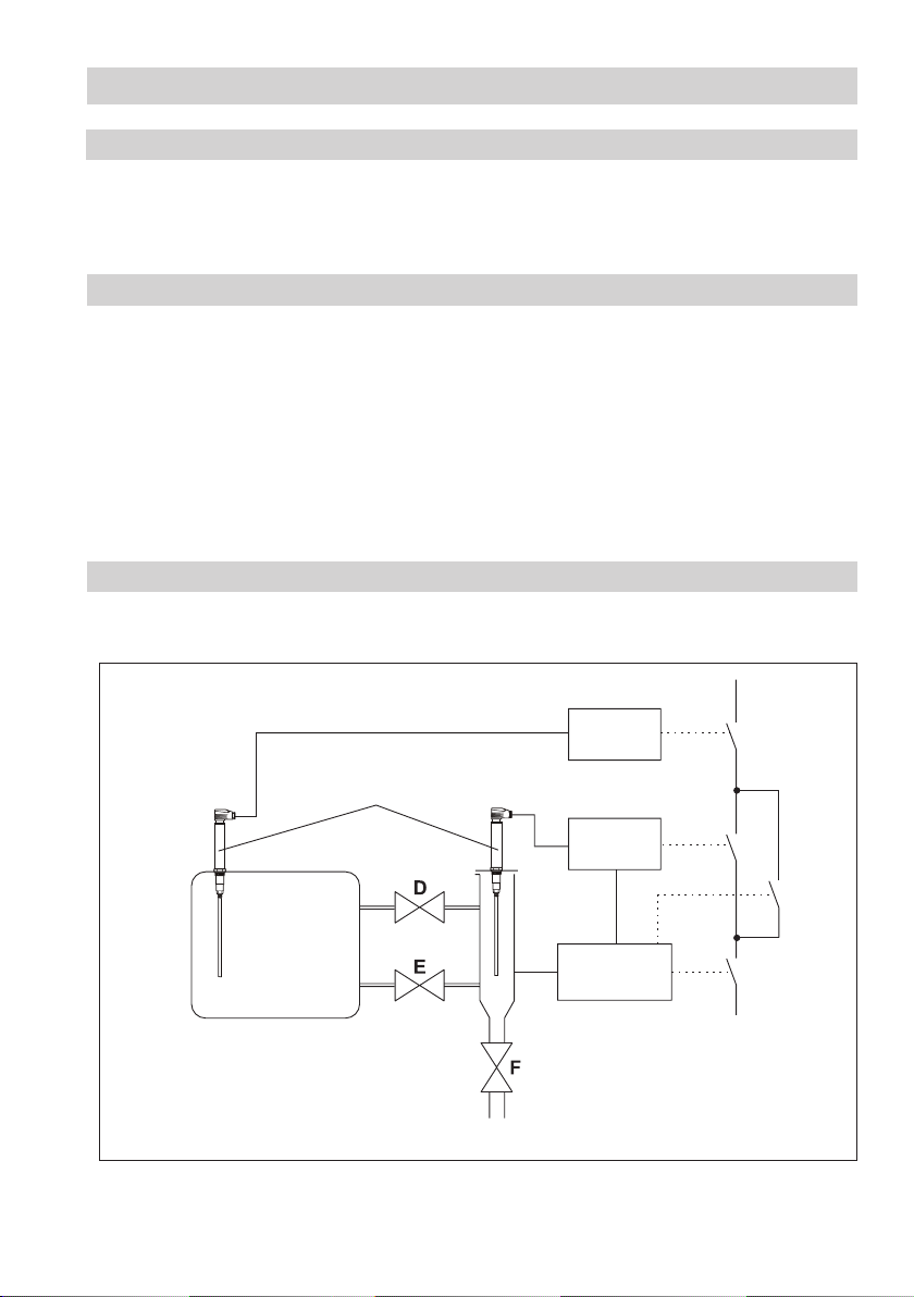
The logic unit monitors the following times:
nInterval time: This is the time interval at which, depending on the mode (24h / 72h operation), the
connecting lines have to be purged.
nStandby period: The purging process must be initiated during this time. The standby period begins
when the interval time has elapsed.
nPurging time: During this period, the purging process must be performed through actuation of
the valves. Actuation of the valves is signalled by means of the limit switches; similarly, when
the electrode of the low-level limiter is exposed, this is sensed through the output contact of the
corresponding level switch. If a signal is not received within the purging time, the safety circuit is
opened. Since a low-level limiter may be bypassed for a maximum of 5 minutes, monitoring of the
purging time is a safety-relevant function.
nSynchronisation: By closing an interconnection valve (E or D) the interval time can be synchronized
at any time: The purging time starts, and when it has elapsed the interval time is reset to its initial
value (e. g. 24h / 72h etc.).
The interval time is started when the logic unit is switched on. The display of the PLC shows the full
hours of the remaining time.
During operation, the standby period is started at the end of the interval time, which is immediately
reset to its initial value (e.g. 24h, 72h etc.). The PLC then starts the purging time when an interconnec-
tion valve (E or D) leaves the end position “Open”.
During the purging time, the output contact of the low-level limiter is bypassed. This bypass is triggered
by the undelayed contact of the safety time-lag relay and limited to 5 minutes by the delayed contact of
this relay.
Once all valves signal that they have reached their initial positions and the level switch of the low-level
limiter senses that the level electrode is exposed, the purging process has ended and the bypassing of
the low-level limiter is terminated.
In the event that the mains supply fails during the purging time, the bypassing of the low-level limiter is
cancelled and the safety circuit is opened. If the mains supply is switched on again, the bypass remains
deactivated and the safety circuit is only closed again after the purging process has been completed
properly.
Expiry of the purging time and standby period, as well as deactivation of the safety circuit, are indicated
by means of pilot lamps.
Explanatory Notes – continued –
The safety circuit is opened when the standby time or the purging time is exceeded, and
it is only closed again when the purging process has been completed properly.
Note

7
Technical Data
SRL 63-a
Inputs
5 volt-free contacts from the limit switches of the valves
1 volt-free contact from a second SRL which may be mounted at the same boiler (interlock)
1 volt-free contact from the low-level limiter
Outputs
2 volt-free change-over contacts each for bypassing/deactivating the safety circuit
Thermal current Ith: 4 A, switching capacity acc. to AC-15: 3 A / 230 V a.c.
1 volt-free change-over contact as a signalling contact for a second logic unit
Contactors must be interference-suppressed as per manufacturer’s instructions (RC combination)
3 contacts for internal or external indication of status (pilot lamps)
Interval time
Adjusted at our works within the range 2 to 336 hours, in compliance with TRD 24/72 h
Standby period
Adjusted at our works within the range 15 minutes to 2 hours, in compliance with TRD 1 h
Purging time
Set at our works to 5 minutes
Indicators and adjustors
1 control panel at the PLC for triggering a test
3 pilot lamps for standby period / purging time, bypassing of the low-level limiter and deactivation of
the safety circuit
Mains voltage
230 V +10 / –15 %, 50 – 60 Hz
Voltage of the safety circuit
230 V, 50 – 60 Hz, optional 24 V, 50 – 60 Hz
Power consumption
26 W
Protection
Enclosure: IP 65 to EN 60529
Permissible ambient temperature
Maximum 55 °C
Case
Field case for wall mounting, with clear lid
Case material: Polystyrene / polycarbonate, colour light gray
Cable entry / electrical connection
5 cable glands, M 16, electrical connection via two terminal strips
Weight
Approx. 3.3 kg

8
Technical Data – continued –
Name plate / marking
Dimensions
308
295
281
260
272.5
281
281
84.5
Wall mounting lugs
5.2
Bereit
Abschalten
Überbrückt
Intervall:
24 h
Rest:8:27h
Q1 Q2 Q3 Q4
I1 I2 I3 I4 I5 I6 I7 I8L+ M
ESC
Interval: 24h
Remaining: 2h
168.2
Standby
Bypass
Shutdown
101.5
Cable glands
5 x M16
Fig. 3
– Designation
Mains voltage /
Power consumption /
–Protection
– Range of application
– Times
– Disposal
– CE marking
Safety note –
Safety circuit –
Fuse –
Manufacturer –
Data for spare parts inventories
Fig. 2
SRL 63-a
Spannungs Sicherheitsstromkreis
IP 65
230 V50/60 Hz
250 V~ T 2,5 A
Münchener Str. 77, D-28215 Bremen
Tamb =55°C(131°F)
Intervallzeit: Bereitschaftszeit: Spülzeit:
xxx Vxx
xx h xh xmin.
26 W

9
Installation
Installing the logic unit SRL 63-a
The case of the logic unit is intended for wall mounting; it should be installed near the external
measuring pot.
Functional Elements
SRL 63-a
Fig. 4
Interval: 24h
Remaining: 2h Control panel

10
Connecting the terminal strips
Connect the terminal strips as shown in the wiring diagram.
The measuring pot is provided with three shut-off valves. Valves D and E are each equipped with two
limit switches, for the “OPEN” position (D1 / E1) and for the “CLOSED” position (D2 / E2).
The drain valve F is only fitted with one limit switch, for the “CLOSED” position.
For connecting the limit switch, we recommend a control cable, e.g. Ölflex 110H, 7 x 1 mm2, length
max. 100 m.
External pilot lamps can be connected to terminals 11 to 14.
Electrical Connection
Check whether the mains voltage matches the voltage of the safety circuit. If this is not
the case, it is necessary to use a logic unit with the correct voltage for the safety circuit.
Note
Attention
If both low-level limiter electrodes of a boiler are installed in external measuring pots,
simultaneous purging and bypassing of the low-level limiters is not admissible.
To prevent this happening, the two logic units must be interlocked by means of parallel
connections between the terminals 16 to 20 of either unit.
In addition:
nTo protect the relay contacts, fit the safety circuit with a fuse T 2.5 A (slow-blow) or
1A (TRD 604, 72 h operation).
Tools
nScrewdriver for slotted screws, size 2.5, fully insulated to VDE 0680-1.
nCross-head screwdriver, size 2.

11
Wiring diagram of logic unit for monitoring SRL 63-a
Electrical Connection – continued –
Fig. 5
Shown switch position of valve limit switch: Valves in normal operating position.
Low-level alarm (electrode exposed), high level (electrode submerged).
Attention
External voltage!
NRS 1-7 Connection for low-level limiter
Standby
Bypass
Shutdown
Shutdown
Standby
Bypass
Burner safety circuit or
pump shut-off
Boiler
Valve: D = steam
E = water
F = drain
Attention
External voltage!
Burner safety circuit
NRS 1-8 Connection for high-level alarm
Interval: 24 h
Remaining:
8:27 h

12
Basic Setting
Factory setting
Logic unit SRL 63-a
The logic unit for monitoring is delivered with the following factory settings:
nInterval time: 24 hours
nStandby period: 1 hour
nPurging time: 5 minutes
nVoltage of safety circuit: 230 V AC
Start-up, Operation, Alarms and Testing
SRL 63-a
Fig. 6
Start-up
Switch on the mains voltage. Interval time starts running. Remaining time is indicated.
Restarting the interval time
Perform the purging process
(see “Operation”).
Green pilot lamp “Standby”
flashes; yellow pilot lamp
“Bypass” is alight.
Purging time is running.
Low-level limiter is
bypassed.
Interval: 24h
Remaining: 2h Control panel

13
Purging
Steam boiler
Purging
Hot-water installation
Purging
Val D OPEN
Val E CLOSED
Val F CLOSED
Purging
Val D CLOSED
Val E CLOSED
Val F CLOSED
Purging
Val D OPEN
Val E CLOSED
Val F OPEN
Purging
Val D CLOSED
Val E CLOSED
Val F OPEN
Opening vent valve*)
Purging
Waiting for LW alarm ...37 sec.
Purging
Val D CLOSED
Val E CLOSED
Val F OPEN
Purging
Val D CLOSED
Val E CLOSED
Val F CLOSED
Purging
Val D CLOSED
Val E OPEN
Val F OPEN
Purging
Val D OPEN
Val E OPEN
Val F CLOSED
Closing vent valve*)
Purging **)
Val D OPEN
Val E OPEN
Val F CLOSED
Purging
Waiting for
normal level
Start-up, Operation, Alarms and Testing – continued –
SRL 63-a – continued –
Operation
Interval time is running. No pilot lamp is alight. Trouble-free operation
Interval time expires and
begins again.
Green pilot lamp “Standby” is
alight.
Standby period is running.
Perform the purging process
as shown on the PLC display.
Green pilot lamp “Standby”
flashes; yellow pilot lamp
“Bypass” is alight.
Purging time is running.
Low-level limiter is bypassed.
End of purging process
Green and yellow pilot lamps
(Standby / Bypass) are
extinguished.
Bypassing of low-level limiter
is cancelled.
Status on the PLC display in
chronological order
Low-level limiter (LW)
Output contact: level switch
NRS 1-7 / NRS 1-9
Valve D
Valve E
Valve F
Boiler
LW
*) Vent valve at measuring pot, if mounted.
**) First close valve F then slowly open valve D.

14
Start-up, Operation, Alarms and Testing – continued –
SRL 63-a – continued –
Alarm
Standby period has expired
without purging process.
Red pilot lamp “Shutdown” is
illuminated. Safety circuit interrupted.
Purging process not completed
in the specified purging time
(5 min.).
For logic unit 1 and 2, the
purging process is started
simultaneously.
The safety circuit is only closed after completion of the purging process
(for sequence, see “Operation”).
Danger
The terminal strips of the logic unit SRL 63-a are electrically live during operation!
This presents the danger of electric shock.
Before working on the terminal strips (assembly, disassembly, connecting the cables),
always cut off power supply!
An external voltage is present at terminal strips X1 (terminals 16 to 20) and X3
(terminals 1 to 5).
Testing the deactivation of the safety circuit
Press the button , then press
until the picture with the
cursor buttons is shown on the
PLC display. Now press ESC and
simultaneously (see picture
below).
The purging time is started.
When the purging time has
ended, the safety circuit is
interrupted and then closed
again after 5 seconds.
Press the button. The display of Fig. 6
is shown again.
Cursor picture in the PLC display

15
Fault finding list
Troubleshooting
Faulty program execution, safety circuit interrupted
Fault: PLC display reports that a limit switch is defective.
Remedy: Exchange the faulty limit switch.
Fault: PLC, safety time-lag relay or coupling relay is defective.
Remedy: Exchange the entire logic unit.
Fault: The mains voltage has failed during the purging time, the bypassing of the low-level limiter
has been cancelled, and the safety circuit is interrupted.
Remedy: Switch on the mains voltage and resume the purging process.
SRL 63-a
Cut off the power supply to the logic unit, undo all the electrical connections and pull the cables out
of the glands. Remove the logic unit.
Decommissioning
Remove and dismantle the logic unit, and separate the waste materials according to the material
specification. Electronic components (PC boards) must be disposed of in the correct manner! For the
disposal of the control device, observe the pertinent statutory regulations concerning waste disposal.
SRL 63-a
Disposal

16
For your notes

17
For your notes

18
For your notes

19
For your notes

20
818588-04/06-2016cm (808615-07)
·
GESTRA AG
·
Bremen
·
Printed in Germany
GESTRA AG
Münchener Straße 77
28215 Bremen
Germany
Telefon +49 421 3503-0
Telefax +49 421 3503-393
E-mail [email protected]
Web www.gestra.de
Agencies all over the world: www.gestra.de
Table of contents