manuals.online logo
Brands
  1. Home
  2. •
  3. Brands
  4. •
  5. BOSSTOW
  6. •
  7. Automobile Accessories
  8. •
  9. BOSSTOW S1035 User manual

BOSSTOW S1035 User manual

Other BOSSTOW Automobile Accessories manuals

BOSSTOW F1195 User manual

BOSSTOW

BOSSTOW F1195 User manual

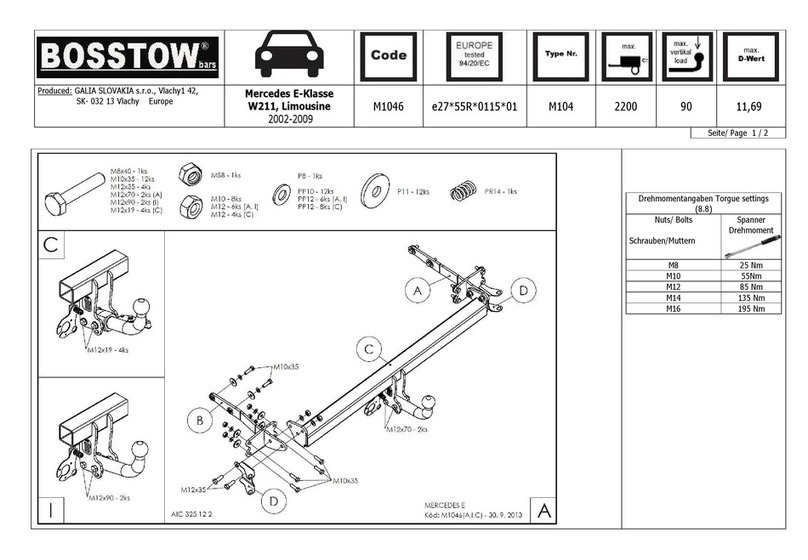
BOSSTOW M1046 User manual

BOSSTOW

BOSSTOW M1046 User manual

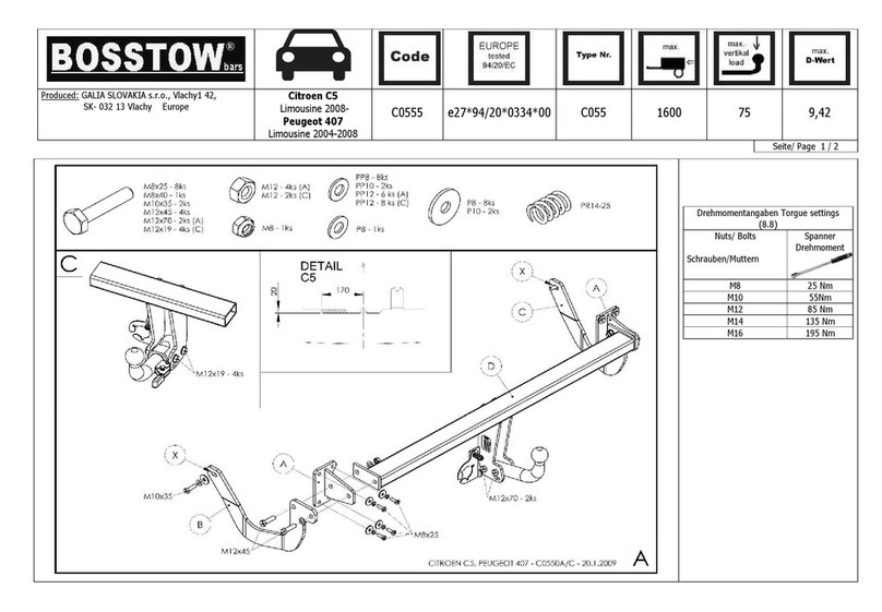
BOSSTOW C0555 User manual

BOSSTOW

BOSSTOW C0555 User manual

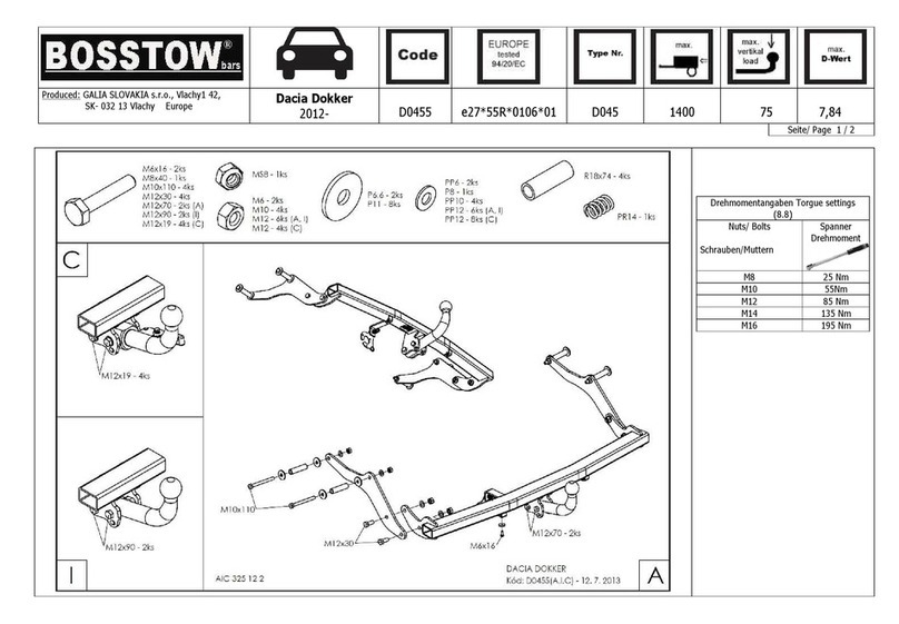
BOSSTOW D0455 User manual

BOSSTOW

BOSSTOW D0455 User manual

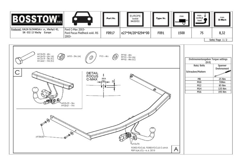
BOSSTOW F0917 User manual

BOSSTOW

BOSSTOW F0917 User manual

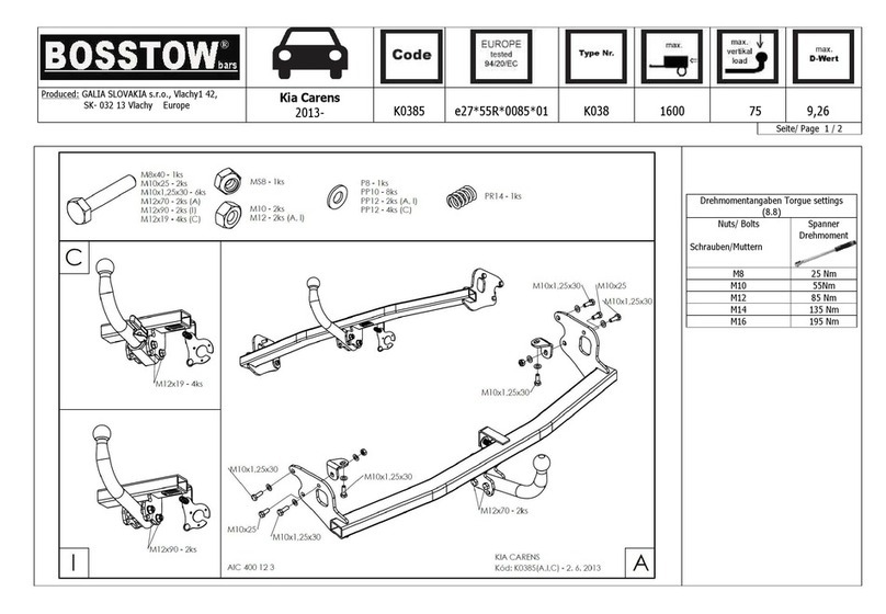
BOSSTOW K0385 User manual

BOSSTOW

BOSSTOW K0385 User manual

BOSSTOW B0215 User manual

BOSSTOW

BOSSTOW B0215 User manual

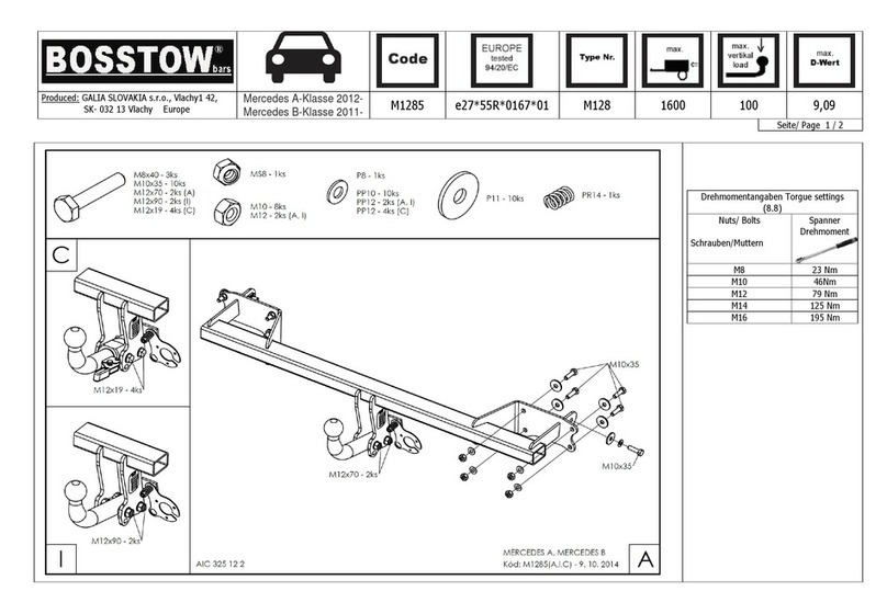
BOSSTOW M1285 User manual

BOSSTOW

BOSSTOW M1285 User manual

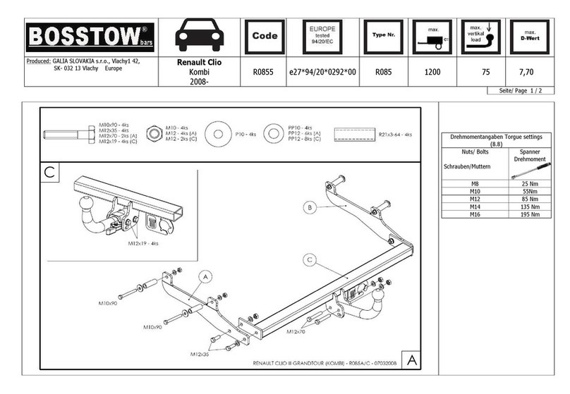
BOSSTOW R0855 User manual

BOSSTOW

BOSSTOW R0855 User manual

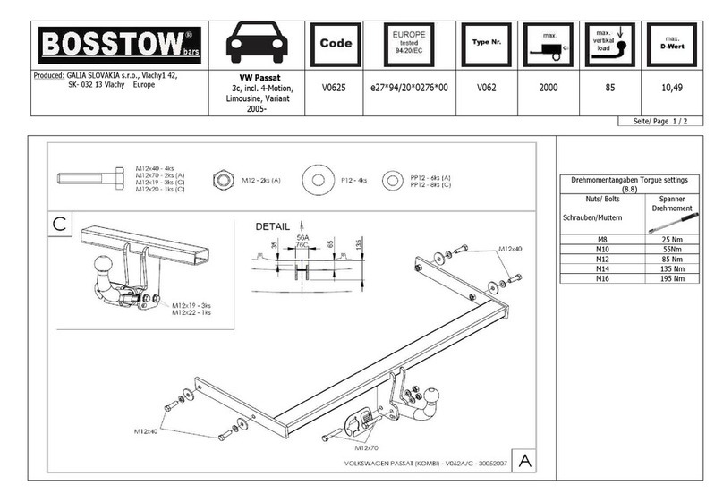
BOSSTOW V0625 User manual

BOSSTOW

BOSSTOW V0625 User manual

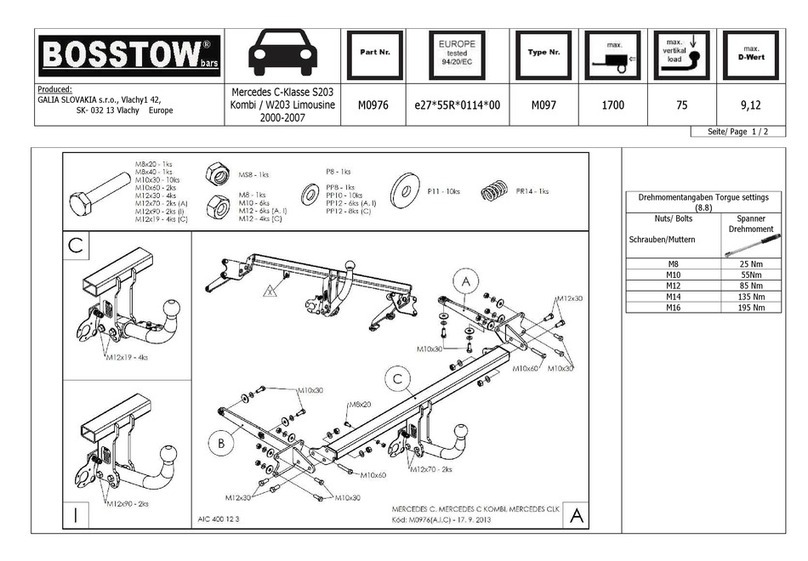
BOSSTOW M0976 User manual

BOSSTOW

BOSSTOW M0976 User manual

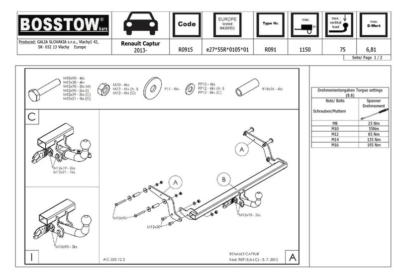
BOSSTOW R0915 User manual

BOSSTOW

BOSSTOW R0915 User manual

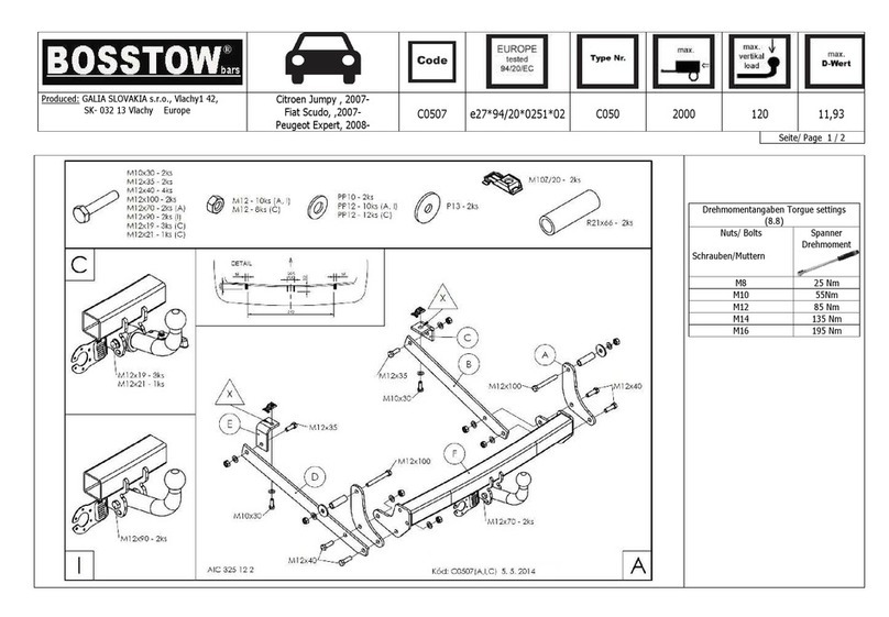
BOSSTOW C0507 User manual

BOSSTOW

BOSSTOW C0507 User manual

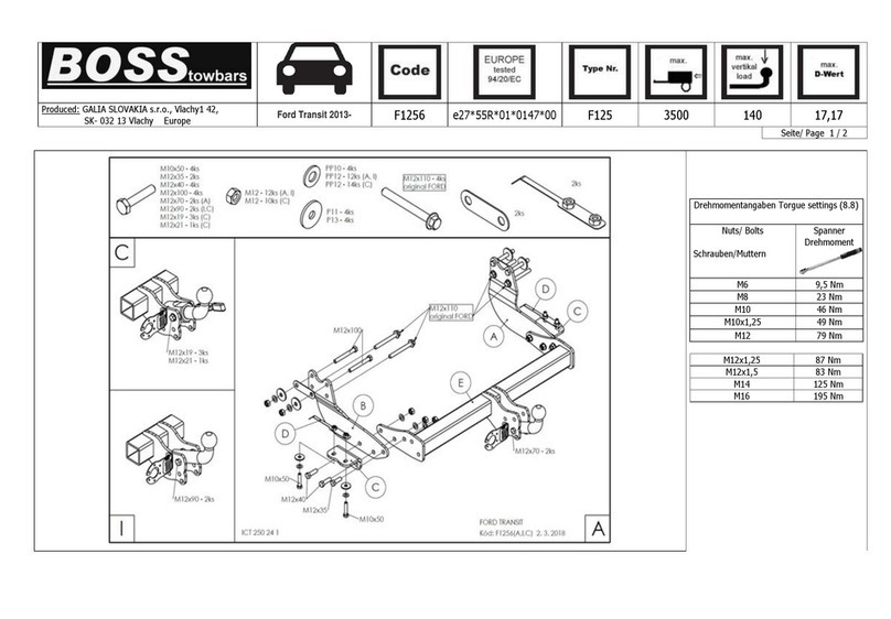
BOSSTOW F1256 User manual

BOSSTOW

BOSSTOW F1256 User manual

BOSSTOW C0665 User manual

BOSSTOW

BOSSTOW C0665 User manual

BOSSTOW J0095 User manual

BOSSTOW

BOSSTOW J0095 User manual

BOSSTOW F1025 User manual

BOSSTOW

BOSSTOW F1025 User manual

BOSSTOW V0646 User manual

BOSSTOW

BOSSTOW V0646 User manual

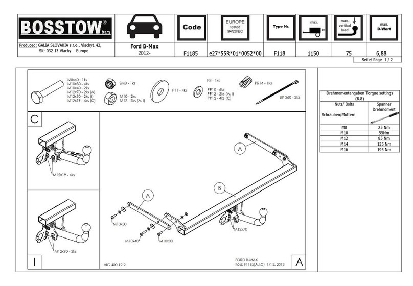
BOSSTOW F1185 User manual

BOSSTOW

BOSSTOW F1185 User manual

BOSSTOW S1305 User manual

BOSSTOW

BOSSTOW S1305 User manual

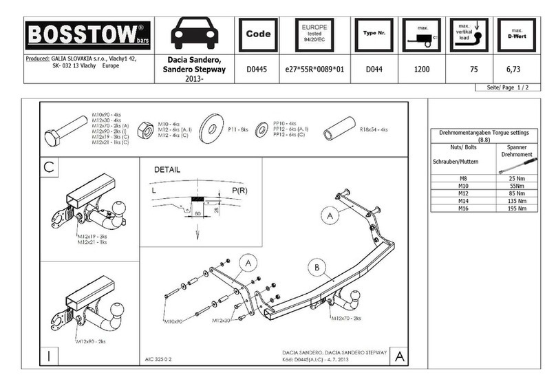
BOSSTOW D0445 User manual

BOSSTOW

BOSSTOW D0445 User manual

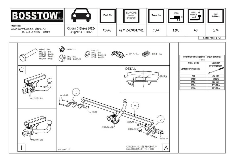
BOSSTOW C0645 User manual

BOSSTOW

BOSSTOW C0645 User manual

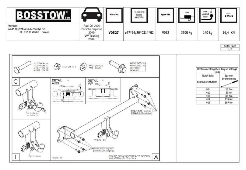
BOSSTOW V0527 User manual

BOSSTOW

BOSSTOW V0527 User manual

BOSSTOW D0465 User manual

BOSSTOW

BOSSTOW D0465 User manual

Popular Automobile Accessories manuals by other brands

Magneti Marelli AC161 Installation instruction

Magneti Marelli

Magneti Marelli AC161 Installation instruction

FDI uEZ GUI Start here

FDI

FDI uEZ GUI Start here

JCROffroad JT Install instructions

JCROffroad

JCROffroad JT Install instructions

Rostra VOXXElectronics 250-1930 owner's guide

Rostra

Rostra VOXXElectronics 250-1930 owner's guide

TOP VEHICLE TECH GR3FORD5 installation manual

TOP VEHICLE TECH

TOP VEHICLE TECH GR3FORD5 installation manual

Safe Fleet PRIME DESIGN AR-2000-BLK manual

Safe Fleet

Safe Fleet PRIME DESIGN AR-2000-BLK manual

Skoda Fabia Combi 5J Fitting instructions

Skoda

Skoda Fabia Combi 5J Fitting instructions

Camcar 40077 Al Mounting instructions

Camcar

Camcar 40077 Al Mounting instructions

Camcar 40089 AL Mounting instructions

Camcar

Camcar 40089 AL Mounting instructions

Impac Tradesman 2000 installation manual

Impac

Impac Tradesman 2000 installation manual

DVB OFFROAD BRSB-01 installation manual

DVB

DVB OFFROAD BRSB-01 installation manual

Safari Snorkel SS385HF installation guide

Safari Snorkel

Safari Snorkel SS385HF installation guide

ULTIMATE SPEED 279746 Assembly and Safety Advice

ULTIMATE SPEED

ULTIMATE SPEED 279746 Assembly and Safety Advice

SSV Works DF-F65 manual

SSV Works

SSV Works DF-F65 manual

ULTIMATE SPEED CARBON Assembly and Safety Advice

ULTIMATE SPEED

ULTIMATE SPEED CARBON Assembly and Safety Advice

Witter F174 Fitting instructions

Witter

Witter F174 Fitting instructions

WeatherTech No-Drill installation instructions

WeatherTech

WeatherTech No-Drill installation instructions

TAUBENREUTHER 1-336050 Installation instruction

TAUBENREUTHER

TAUBENREUTHER 1-336050 Installation instruction

manuals.online logo
manuals.online logoBrands
  • About & Mission
  • Contact us
  • Privacy Policy
  • Terms and Conditions

Copyright 2025 Manuals.Online. All Rights Reserved.

Produced: GALIA SLOVAKIA s.r.o., Vlachy1 42,
SK- 032 13 Vlachy Euro e
Subaru Forester
2008-
S1035
e27*55R*01*0048*00
S103
2200
80
10,54
Seite/ Page 1 / 2
Drehmomentangaben Torgue settings
(8.8)
Nuts/ Bolts
Schrauben/Muttern
S anner
Drehmoment
M8 25 Nm
M10 55Nm
M12 85 Nm
M14 135 Nm
M16 195 Nm
Produced: GALIA SLOVAKIA s.r.o., Vlachy1 42,
SK- 032 13 Vlachy Euro e
Subaru Forester
2008-
S1035
e27*55R*01*0048*00
S103
2200
80
10,54
Seite/ Page 2 / 2
Deutsch
english
•
Lesen Sie die Montageanleitung und Übersicht komplett durch. Die Montage ist fachgerecht
durchzuführen. Bei Fragen kontaktieren Sie bitte den Lieferanten.
•
Demontieren Sie die Rückleuchten und die Stoßstange.
•
Entfernen sie den Metallinnenträger (Dieser wird nicht mehr benötigt).
•
Senken Sie den Aus uff ab und demontieren sie das Hitzeschutzschild.
•
Befestigen sie die Teile A, B und C lose an den Längsträgern und der Rückwand des
Fahrzeugs (Bei den Punkten X werden die Originalmuttern benutzt).
•
Befestigen sie das Teil D lose an den Teilen B und C.
•
Ziehen sie alle Schrauben gemäß Drehmomenttabelle fest.
•
Nehmen sie einen Ausschnitt gemäß Abbildung in der Unterseite der Stoßstange vor.
•
Montieren sie alle demontierten Teile wieder am Fahrzeug.
•
Montieren sie den Kugelhals und die Steckdosenplatte und ziehen sie die Schrauben fest.
•
Diese Montageanleitung ist für das feststehende und das abnehmbare System gültig.
•
Alle Schrauben sind nach jeweils 1000 km oder spätestens 6 Monaten zu überprüfen und
ggf. fachgerecht nachzuziehen. Nach der Montage ist ein Korrosionsschutz auf der
Anhängerkupplung aufzubringen- dieser ist laufend zu prüfen und ggf. zu erneuern, um
Korrosion zu vermeiden.
•
Je nach Ausstattungsvariante und Baujahr kann ein Ausschnitt des Stoßfängers
zur Nachrüstung erforderlich sein.
•
Von uns gemachte Angaben zum Ausschnitt des Stoßfängers sind nur eine unverbindliche
Hilfestellung. Ein Ausschnitt ist, soweit erforderlich, fachgerecht im Zuge der Montage
vorzunehmen.
•
Diese Anhängerkupplung ist im Regelfall eintragungsfrei- und verfügt über die auf Grundlage
der § 19 Abs. 3 StVZO EG- Typgenehmigung (siehe Prüfnummer europe tested).
•
Die Montageanleitung ist im Fahrzeug mitzuführen.
Fitting instructions:
•
Check out the delivery.
•
Remove the rear lights, the rear
plastic bumper and metal
element bumper. The metal insert
is already not just nuts. Loosen
the exhaust and aluminum shield.
Loosen the screws and aluminum
exhaust shield on beams.
Remove 6pcs rubber hole cover.
•
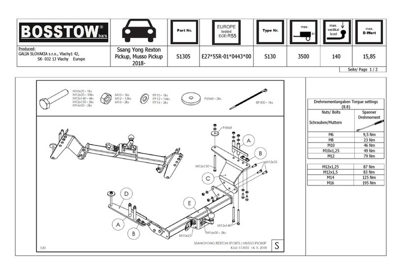
Install the tow-bar in parts as
shown in the picture. Insert into
beams A and parts washers
P20x25x8. Screw the B, C side
consoles freely onto the
longitudinal bars and then join the
D frame to these consoles. The
points X, use the original nut
M10x1, 25 - 6 pcs. Torque all the
screw connections as shown in
the table.
•
Cut a cavity in the bumper bottom
as shown in the picture -
DETAIL.
•
Replace the rear plastic bumper
without the metal reinforcement,
which will be replaced by the tow-
bar frame.
•
Reassemble any removed parts.
•
Fit the linkage ball. Tighten the
screws of the linkage ball (holder
of the linkage ball) to the torque
shown in the table.