Boyd C300 Series User manual

1
IG-001
Rev 1
Product Installaon Guide
C300 & C500 Series LED Exam Light
Installaon and Operaon
12900 44th Street North
Clearwater, Florida 33762
800-255-2693 or 727-561-9292
FAX: 727-561-9393 SALES
FAX: 727-573-1682 SERVICE
www.boydindustries.com
C300 C500

2
IG-001
Rev 1
Table of Contents
Title Page
Table of Contents
Introducon
Applicaon of Product
Warranty Informaon
Safety Tips / Precauons
About Your LED Light
Components
Product Installaon
Product Operaon
Tension Adjustment
General Maintenance and Repair
Lens Removal C300 and C500
Cleaning / Infecon Control / Technical Service Informaon
Authorized Representave (Europe Only)
1
2
3
4
5-14
15-17
18

3
IG-001
Rev 1
Intended Use and Application of Product
This light is designed and intended to illuminate paents for examinaons and procedures. Its exibility allows for posioning that
is clear of the work area and precise for opmal visibility.
Warranty Statement
All Boyd manufactured products are warranted against defects in material or workmanship only. No other warranes are
expressed or implied. This warranty shall extend for three (3) years for parts and one (1) year for labor. The warranty only covers
products manufactured by Boyd. Products distributed, not manufactured by Boyd, carry the stated manufacturer’s warranty.
The warranty period commences upon invoice date of the equipment. Wrien noce of breach must be submied to Boyd
Industries, Inc. within this period. Boyd reserves the right to repair or replace, at its sole discreon, the item in queson.
Warranty is voided if items are misused or product is improperly maintained or installed. The warranty does not cover any
alteraon of the product from its original condion or if product is used in any way other than the product’s design intent.
An authorized service technician must perform all service and maintenance. Any warranty labor must be rst approved by Boyd.
Failure to coordinate warranty service may result in denial of warranty repair. Wrien log and receipts for service must be
maintained to validate the warranty on Boyd manufactured products.
No claim for consequenal damages will be allowed. Freight damage or mishandling by any third party will not be considered a
warranty item. Improper installaon by a third party causing damage to the equipment is not a warranty item.
Introducon
Congratulaons
on your purchase of a LED Exam Light
Boyd Industries, Inc. is proud of this product. We are sure that you will enjoy its ease of use and adjustability for many years to
come. It is our goal to please our customers with the best product quality in the market today.
Aluminum Support Arms
Adjustable Posioning
Adjustable Light Intensity
Foot and Hand Control
Integrated Camera with control panel and remote control (C500 camera opon only)
Camera maximum zoom 30X (C500 camera opon only)

4
IG-001
Rev 1
1. The Boyd LED Exam Light has been designed to be safe and eecve when used for paent dental examinaon when properly
installed, used, monitored and maintained.
2. Prior to installation, visually examine the light head, lens, arms, power cords, video cables, transformer and plugs for any sign of
damage or deterioration.
3. Disable, disconnect or de-energize the power circuit that the light will be installed on prior to installation and throughout the
installation process. This should be accomplished by turning off the power at the breaker box or by unplugging the chair that the light
is attached to. The chair should be unplugged or otherwise de-energized to prevent accidental movement while working under or
around the chair.
4. Please use caution when using illumination of Boyd LED exam lights to avoid unnecessary glare into the patient’s eyes. Prolonged
exposure of LED light may cause eye irritation or permanent eye injury.
5. Regular disinfection / sterilization is required in order to prevent contamination.
6. Avoid use of cleaning agents including benzene, bleach, thinners or other harsh chemicals as they may cause discoloration and other
hazards.
7. Instruments and other items should not be attached or hung from the light or arms.
8. Gloves should be worn when handling the Boyd light in order to prevent inadvertent scratching or damage.
9. Do not store near unsafe chemicals or flammable materials. Lights are not rated or suitable for use in explosive environments.
Note: This installaon guide depicts the Boyd C300 and C500 LED Exam Lights. The processes of installation, operation and
maintenance are the same for both units. Refer to the Service & Repair Manual for any issues beyond the scope of this document.
Safety Tips and Precauons
Please read the installaon guide before use.
Warnings & Cauons
Unplug before performing maintenance procedures on this product.
Do not use bleach for cleaning on this product.
Handle this product and internal parts with care during maintenance procedures.
5
IG-001
Rev 1
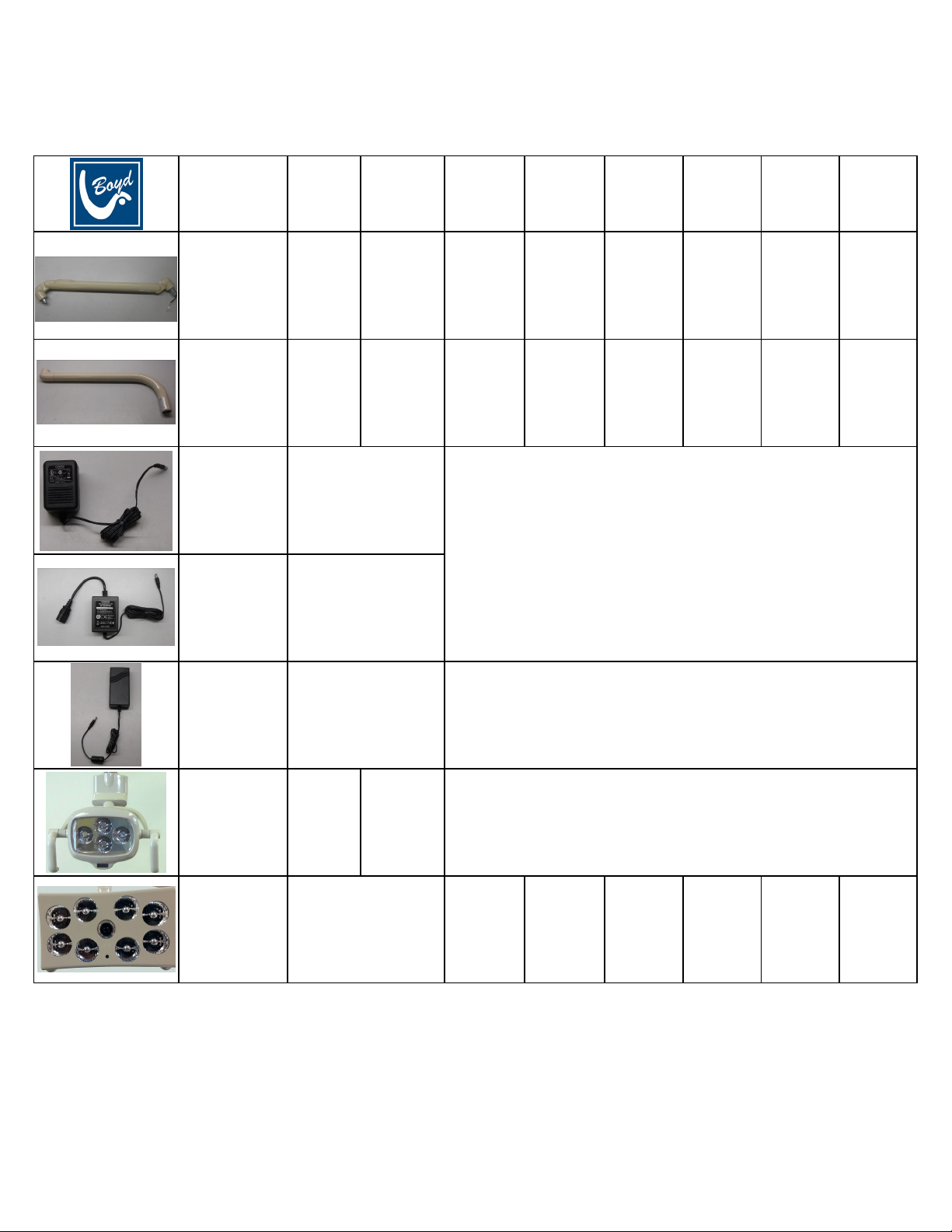
Components C300 / C500
About Your LED Light
Descripon C300
Puy
C300
Black
C500
Puy
C500
Black
C500
White
C500
Puy
Camera
C500
Black
Camera
C500
White
Camera
Primary Arm 60-7923 60-7923B 60-7924 60-7924B 60-7924W 60-7925 60-7925B 60-7925W
Secondary Arm 60-7926 60-7926B 60-7927 60-7927B 60-7927W 60-7927 60-7927B 60-7927W
Transformer
115V 10-5555
N/A
Transformer
230V 10-5556
Transformer
115V ~ 230V N/A 10-5557
Light Head
C300 60-7911 60-7911B N/A
Light Head
C500 60-7931 60-7931B 60-7931W 60-7930 60-7930B 60-7930WN/A
This manual suits for next models
1
Table of contents
Other Boyd Medical Equipment manuals


Popular Medical Equipment manuals by other brands


Getinge
Getinge Arjohuntleigh Nimbus 3 Professional Instructions for use

Mettler Electronics
Mettler Electronics Sonicator 730 Maintenance manual

Pressalit Care
Pressalit Care R1100 Mounting instruction

Denas MS
Denas MS DENAS-T operating manual

bort medical
bort medical ActiveColor quick guide

AccuVein
AccuVein AV400 user manual


