10
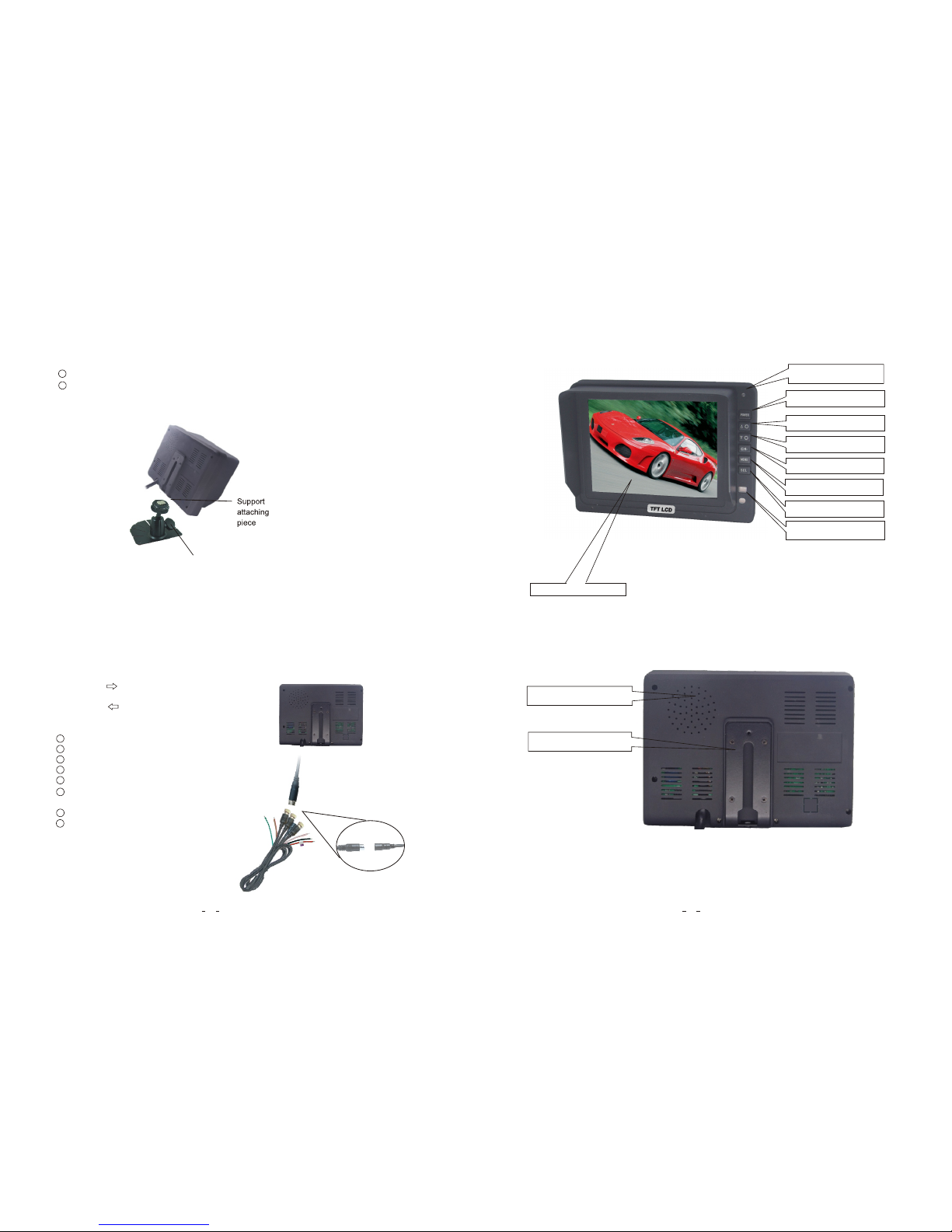
2. Features
3. Technical Specifications
1. TFT LCD monitor with wide angle view and high resolution display.
2. Picture image may be adjusted for Horizontal, Vertical, Mirror and Normal viewing.
3. Select from 3 languages for user operation.
4. Automatic backlighting for buttons.
5. Full-function remote control.
6. Multiple video formats available: AUTO/ PAL / NTSC.
7. Up to 3 AV inputs.
8. Operates from 12 - 32V. Supports 12V or 24V automobile battery.
9. Automatically switches to back-up, left or right side camera views.
10. On-board speaker.
11. OSD keeps normal image even if it is mirror image in horizontal.
3
!
Special Notice
All specifications are subject to change without notice.
8. Menu
Press MENU to display the following options and settings:
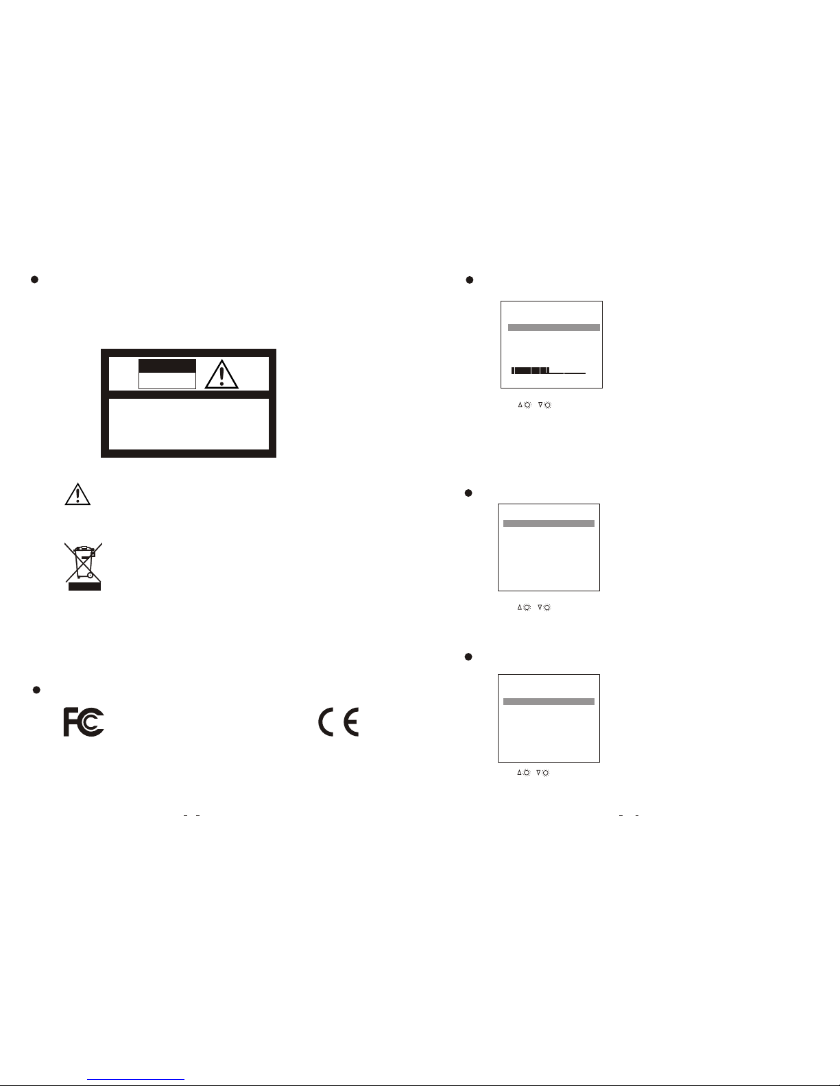
1. PICTURE
2. OPTION
3. SYSTEM
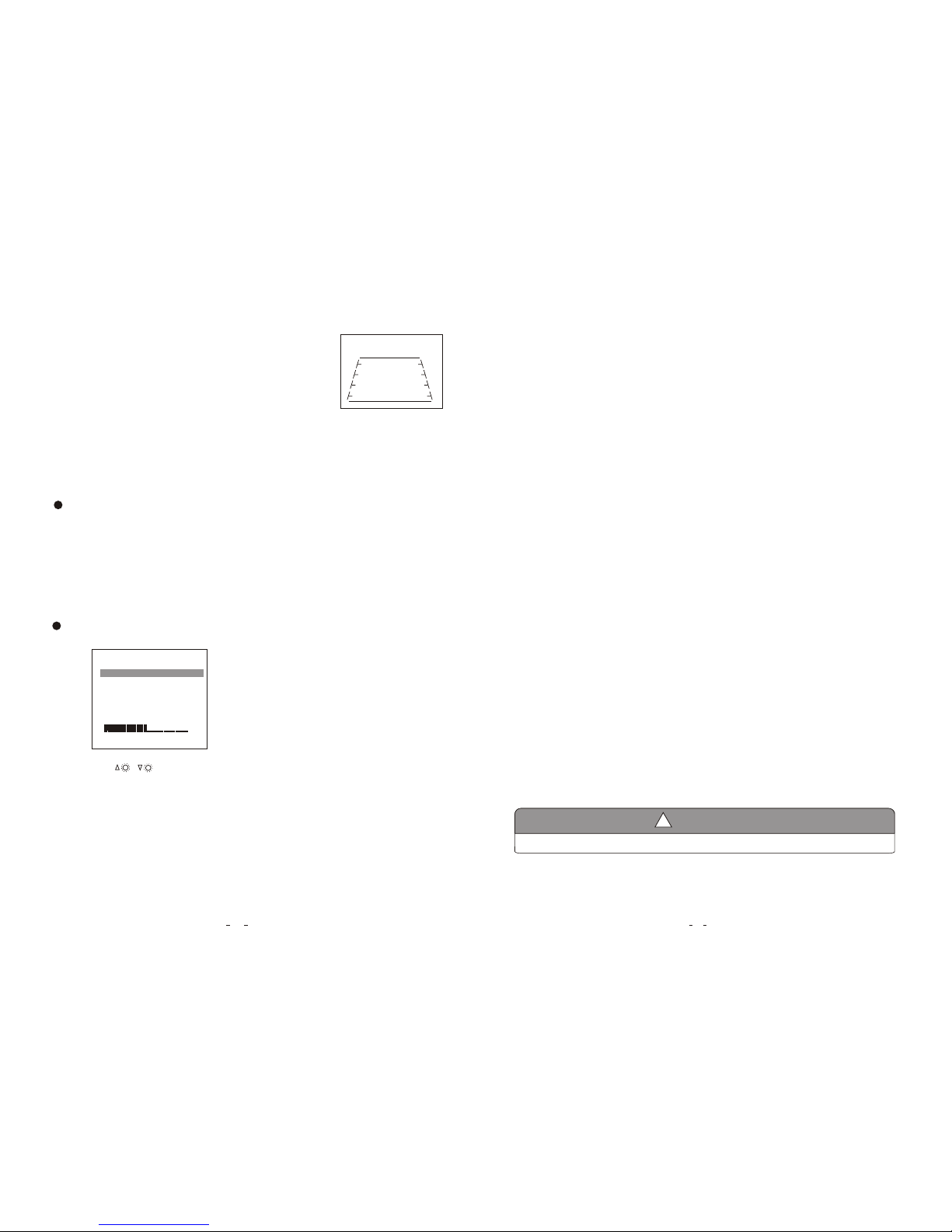
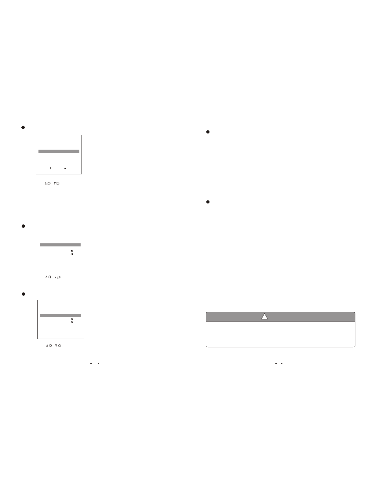
(1) Picture
The BRIGHT,CONTRAST, COLOR, VOLUME options
will display on the screen as illustrated below:
Press CH- to select BRIGHT.
Press / to adjust the BRIGHT Level.
PICTURE
BRIGHT
CONTRAST
COLOR
VOLUME
50
50
50
50
50
3. When the brown wire is connected to the positive wire of back-up light,
the monitor automatically switches to CAM 3 (back-up camera) when
the back-up light is turned on. The distancing grid will also be displayed.
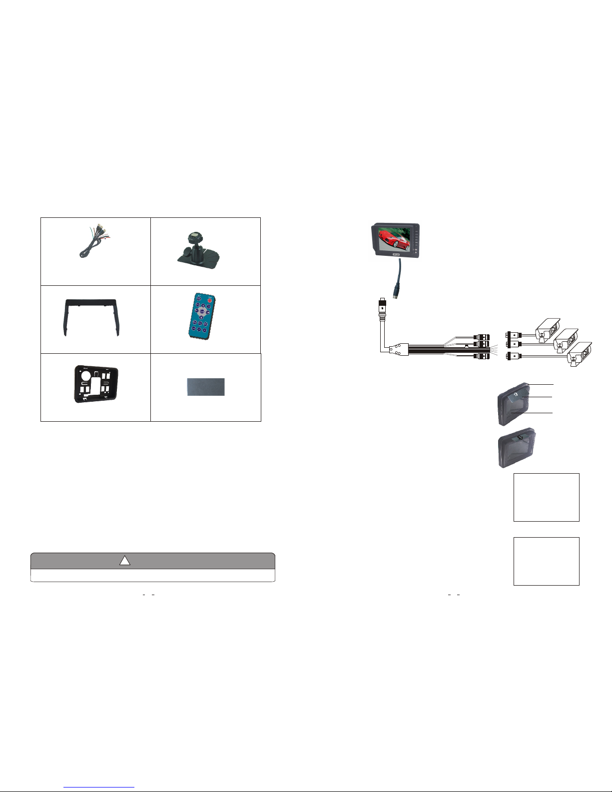
1. Product: 5" Digital TFT- LCD Color monitor.
2. Audio output: 1W.
3. Loudspeaker: one 4.0cm round loudspeaker.
4. Power supply: Automobile storage battery (12-32V).
5. Power consumption: < 7 W .
6. Outer dimension: 147.6mm (W) × 109mm (H) × 26.5mm (T) (without flush mount),
165mm (W) × 126mm (H) × 29.2mm (T) (with flush mount).
7. Dot pitch: 0.0529(H) × 0.1587 (V).
8. Resolution: 640 x 3(RGB) x 480 .
9.Color depth:24 bit
10.Display colors:16.7M dithering.
11.Contrast: 500:1.
2
12.Brightness: 200cd/m .
13.Viewing angle: U: 50 / D: 70, R/L: 70.
14.Operating temperature: -20~+70ºC,RH90%.
15.Storage temperature: -30~+80ºC,RH90%.