Bradford White FT Series User manual
800.900.9276 •Fax 800.559.1583 (Customer Service, Service Advisors)
20 Industrial Way, Rochester, NH 03867 •603.335.6300 •Fax 603.335.3355 (Applications Engineering)
1869 Sismet Road, Mississauga, Ontario, Canada L4W 1W8 •905.238.0100 •Fax 905.366.0130
www.Laars.com
Document 4288D
The FT Series, Wall Combi, Gas Conversion Kit
pg 1 of 4
The FT Series, wall combi, condensing boiler is
congured for Natural Gas (NG) from the factory.
A Natural Gas to Propane Conversion Kit is included
with every FT. The gas conversion kit will show you
how to convert your FT boiler to propane gas. If your
FT does not have the bag containing the conversion
kit, a replacement kit can be obtained. Contact the
manufacturer and request a replacement conversion kit.
NOTICE
If your installation altitude is greater than 2000 ft, check
that the ‘High Altitude’ Installer Setting has been adjusted
to suit your installation altitude. Refer to Section 4.12 of the
Installation and Operation Instructions (Document 1318).
WARNING
This gas conversion kit shall be installed by a qualied
service agency in accordance with the manufacturer’s
instructions and all applicable codes and requirements of
the authority having jurisdiction. The information in these
instructions must be followed to minimize the risk of re or
explosion or to prevent property damage, personal injury
or death. The qualied service agency is responsible for
the proper installation of this kit. The installation is not
proper and complete until the operation of the converted
appliance is checked as specied in the manufacturer’s
instructions supplied with the kit.Installation must conform
to local codes and the latest edition of the National Fuel
Gas Code, ANSI Z223.1 and CAN-B149.1. Failure to
follow instructions could result in serious injury or property
damage. The qualied agency performing this work
assumes responsibility for gas conversion.
CAUTION
This combination boiler has already been set to burn natural
gas, but can be converted to burn LP gas. Before placing the
combination boiler into operation, verify that the type of gas
supplied to your combination boiler.
Steps 1 thru 25
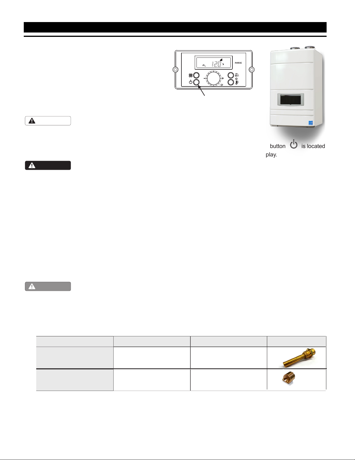
1.
Turn OFF the FT. The ON / OFF button is located at
the bottom left of the Control Display.
2.
Turn OFF the GAS and WATER supply to the FT (valves
are located on the plumbing pipes.)
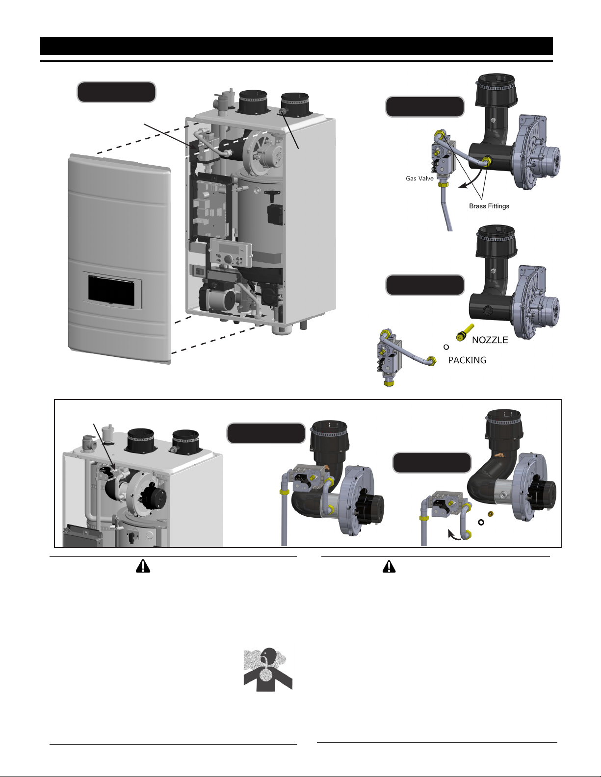
3.
Using a Phillips screwdriver, remove the 4 screws on the
front cover. See Figure A.
4. Locate the Gas Inlet Pipe at the top left of the unit as
shown in Figure A, and loosen the Brass Fittings at both
ends of the Gas Inlet Pipe.
5. Completely unthread the brass tting on the blower end of
the Gas Inlet Pipe and then carefully swing the Gas Inlet
Pipe to the left or right, just enough so that it is out of the
way. See Figure B.
6. Remove the existing natural gas nozzle or orice. If your
unit is a 199, note that the at side of the orice is towards
the blower. Save the packing for re-use. See Figure C.
7. Install the new LP (propane) nozzle or orice. Re-use the
packing from previous.
8. Return the Gas Inlet Pipe to its original position and tighten
both of the brass ttings.
ON / OFF
H2373800D
Model Natural Gas (NG) part # Propane Gas (LP) part #
FTCW140
FT1412N
FT1412P
FTCW199 FT1780 FT1802
Nozzle
Orice
Kit # R20770
Table A. Gas Conversion Parts
800.900.9276 •Fax 800.559.1583 (Customer Service, Service Advisors)
20 Industrial Way, Rochester, NH 03867 •603.335.6300 •Fax 603.335.3355 (Applications Engineering)
1869 Sismet Road, Mississauga, Ontario, Canada L4W 1W8 •905.238.0100 •Fax 905.366.0130
www.Laars.com
Document 4288D
The FT Series, Wall Combi, Gas Conversion Kit
pg 2 of 4
WARNING
This conversion shall be installed by a qualied
service agency in accordance with the manufacturer's
instructions and all applicable codes and requirements
of the authority having jurisdiction. If the information
in these instructions is not followed exactly, a re,
an explosion or production of carbon
monoxide may result causing property
damage, personal injury or loss of
life. The qualied service agency is
responsible for the proper and complete
installation of this kit. The installation is
not proper and complete until the operation of the
converted appliance is checked as specied in the
manufacturer's instruction supplied with the kit.
Figure C
Figure A
AVERTISSEMENT
Ce conversion doit être installé par un organisme de
service conformément aux instructions du fabricant
et tous les codes et les exigences de l’autorité
compétente. Si les informations contenues dans ces
instructions n’est pas suivi à la lettre, un incendie,
une explosion ou de la production de monoxyde
de carbone mais résultat causant des dommages
matériels, des blessures ou des pertes de vie. Le
service est responsable pour la bonne et complète
l’installation de ce kit. L’installation n’est pas correcte
et complète jusqu’à ce que le fonctionnement de
l’appareil converti est vériée comme spécié dans
le manuel d’instruction fourni avec le kit.
Figure B
Gas Valve
Gas Valve
ORIFICE
PACKING
FTCW140
FTCW199
Figure C
Figure B
Gas Valve
Combustion
Test Port
800.900.9276 •Fax 800.559.1583 (Customer Service, Service Advisors)
20 Industrial Way, Rochester, NH 03867 •603.335.6300 •Fax 603.335.3355 (Applications Engineering)
1869 Sismet Road, Mississauga, Ontario, Canada L4W 1W8 •905.238.0100 •Fax 905.366.0130
www.Laars.com
Document 4288D
The FT Series, Wall Combi, Gas Conversion Kit
pg 3 of 4
Gas Valve
Adjustment Port
+
+
-
-
Gas Valve
Adjustment Port
Figure D
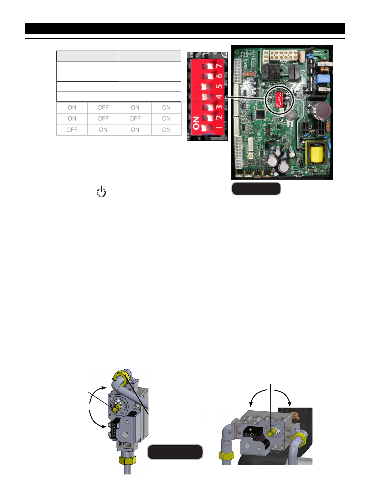
Table B DIP Switch Settings
9.
Per Table B, set DIP Switch 5 to OFF for LP Propane.
10. Turn ON the GAS and WATER supply to the FT.
11. Turn ON the FT.
12.
Connect a manometer to the manifold pressure port. For dual port manometers, use the positive pressure
side. Check for proper manifold gas pressure. Refer to Table D.
13.
Establish a call for heat. You may need to disconnect the outdoor reset if you are making this gas conversion
during warm weather.
14. Setup your combustion analyser and place the sensor into the combustion test port
15.
Per Table B for Max Fire, change dip switch 6 to ON and 7 to OFF. The unit will cycle up to MAX re.
16.
WAIT for your combustion analyser to stabilize. This may take up to 3 minutes depending on your
combustion analyser. Then check the CO2 measurement for MAX re. Refer to Table C for acceptable MAX
re combustion readings Do NOT attempt to adjust CO2 at MAX Fire. ONLY in MIN Fire,
so...
17.
Per Table B for MIN Fire, change dip switch 6 to OFF and 7 to ON. The unit will cycle down to MIN Fire.
18.
WAIT for your combustion analyser to stabilize. Then check the CO2 measurement for MIN re. Refer to
Table C for acceptable MIN re combustion readings
19.
Open the Gas Valve Adjustment Port by removing the cap screw with a 4mm Allen wrench.
20.
Then use the 4 mm Allen wrench to make a minor adjustment (1/8 turn) to either increase or decrease CO2.
Figure E
MBH N/A 140 N/A 199
ON OFF
MIN Fire Normal Operation
MAX Fire Normal Operation
NG Natural LP Propane
3” Vent Size 2” Vent Size
ON OFF ON ON
ON OFF OFF ON
OFF ON ON ON
DO
NOT
CHANGE
REFERENCE
ONLY.
FTCW140 FTCW199
800.900.9276 •Fax 800.559.1583 (Customer Service, Service Advisors)
20 Industrial Way, Rochester, NH 03867 •603.335.6300 •Fax 603.335.3355 (Applications Engineering)
1869 Sismet Road, Mississauga, Ontario, Canada L4W 1W8 •905.238.0100 •Fax 905.366.0130
www.Laars.com
Document 4288D
The FT Series, Wall Combi, Gas Conversion Kit
pg 4 of 4
Figure F (Conversion label)
This unit was converted on ____/____/___to _____gas
with kit #____________by______________________
(name and company __________________________
accountable)_________________________________
___________________________________________
Cette unité a été converti ____/____/____ten ______gaz
en utilisant le kit numéro _____ par______________
(nom et société_________________________________
responsable)___________________________________
_____________________________________________
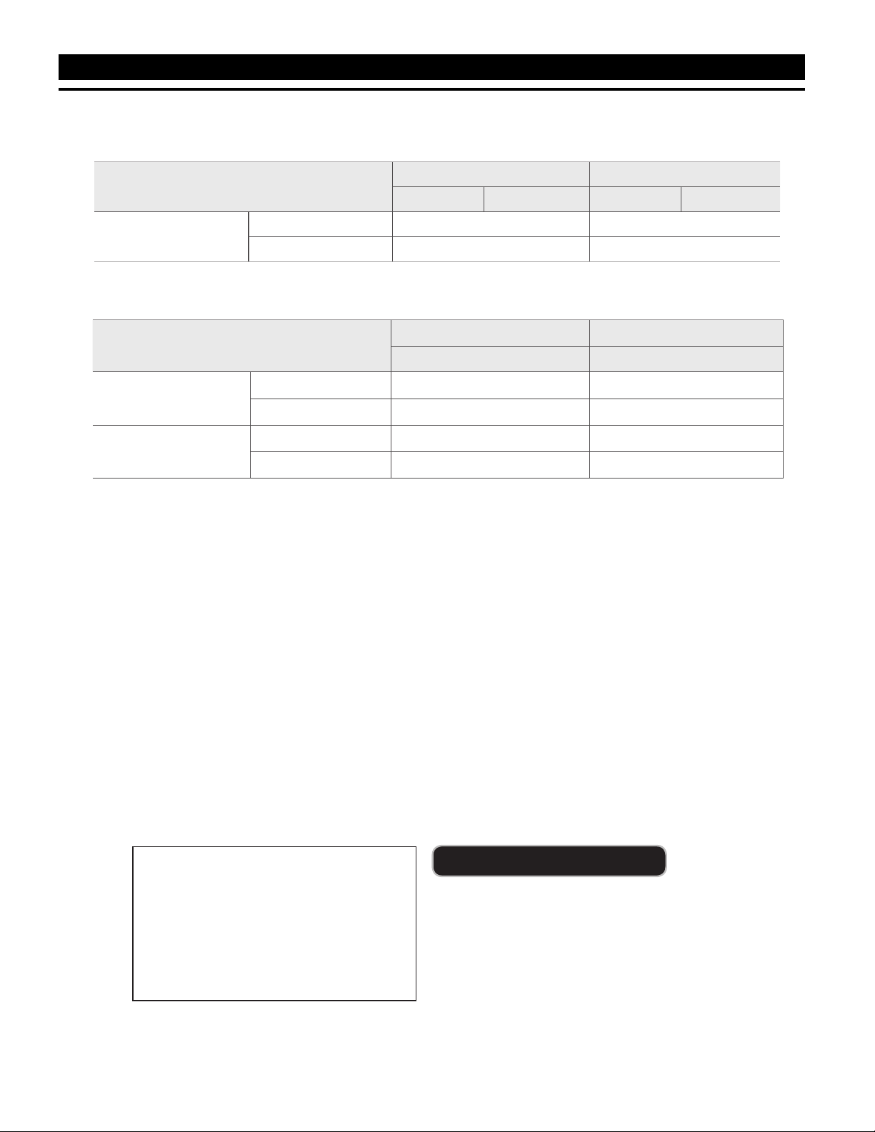
CO2value
Natural Gas (NG) Propane Gas (LP)
2˝ VENT 3˝ VENT 2˝ VENT 3˝ VENT
FTCW (ALL Sizes) MAX FIRE 8.5 - 10.5% 9.5 - 11%
MIN FIRE 8 - 10% 9 - 10.5 %
NOTE: Installer is required to verify combustion settings as part of the installation process.
CO should not exceed 200 ppm.
H2373800D
Manifold pressure ‘NG’ type combustibility ‘LP’ type combustibility
2"/3" VENT 2"/3" VENT
FTCW140
MAX FIRE -0.216
"
WC -0.216
"
WC
MIN FIRE 0.002
"
WC 0.079
"
WC
FTCW199
MAX FIRE -0.314
"
WC -0.173
"
WC
MIN FIRE -0.015
"
WC -0.015
"
WC
21. It may be necessary to go back and forth between HI Fire and LOW Fire several times (and making
adjustments only at LOW Fire), before CO2 at both are within acceptable levels. Be sure to put the
adjustment port cap screw back onto the valve when done.
22. Once the CO2 and manifold pressure measurements for both MIN and MAX Fire are acceptable per
Table C, set DIP switches 6 and 7 to the OFF position for Nominal Fire (normal operation).
23. Write in the correct Conversion Date and the Technicians Name to the included gas conversion
sticker. See Figure F. Then apply that sticker adjacent to the rating plate.
24. Remove your combustion analyser from the Test Port and be sure to thread the Test Port plug back
into position.
25. Re-connect outdoor reset if it was disconnected, put the boiler cover back on and assemble/tighten
the 4 screws that hold the cover in place.
Table C
Table D
Other manuals for FT Series
3
This manual suits for next models
2


