CALDAIE TIPO E FAMILY
INS
pressing the relevant key (Local/Remote) on it.
C
AB
D
TALLAZIONE SCHEDAINTERFACCIAITRF11
1) Se nelcruscottodellacaldaiaègiàpresente laschedaITRF12,
sostituirla con la sdcheda ITRF11 effettuadno i medesimi col-
legamenti elettrici
2) Se nel cruscotto della caldaia non è già presente la scheda
ITRF12 procedere come di seguito descritto:
Prima di effettuare qualunque operazione togliere l’alimentazione
elettrica alla caldaia posizionando l’interruttore generale dell’im-
pianto e quello principale dell’apparecchio su “spento”.
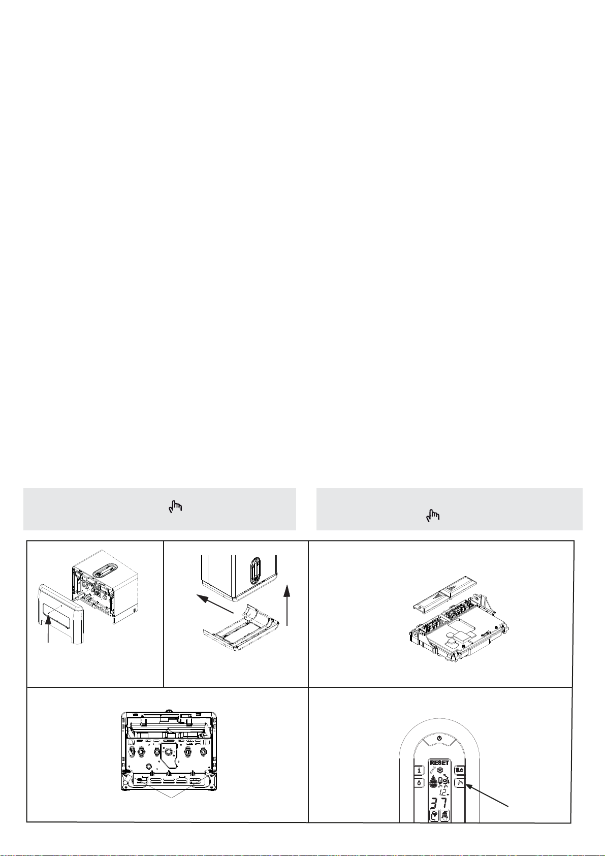
Per accedere al cruscotto di caldaia procedere come descritto
di seguito:
- svitarelavitedifi
ssaggio(C fig. 1)della coperturaraccordi,
- sfilare la copertura raccordi dalla sua sede tirandola verso di sé
(A-B fig. 2)
- svitare le viti (D - fig. 3) di fissaggio del mantello
- spostare in avanti e poi verso l’alto la base del mantello per sgan-
ciarlo dal telaio (fig. 4)
- sollevare il cruscotto e successivamente ruotarlo in avanti
- svitare le viti di fi
ssaggio dei coperchietti morsettiere e aprirli
facendoli scorrere nel senso delle frecce (fig. 5).
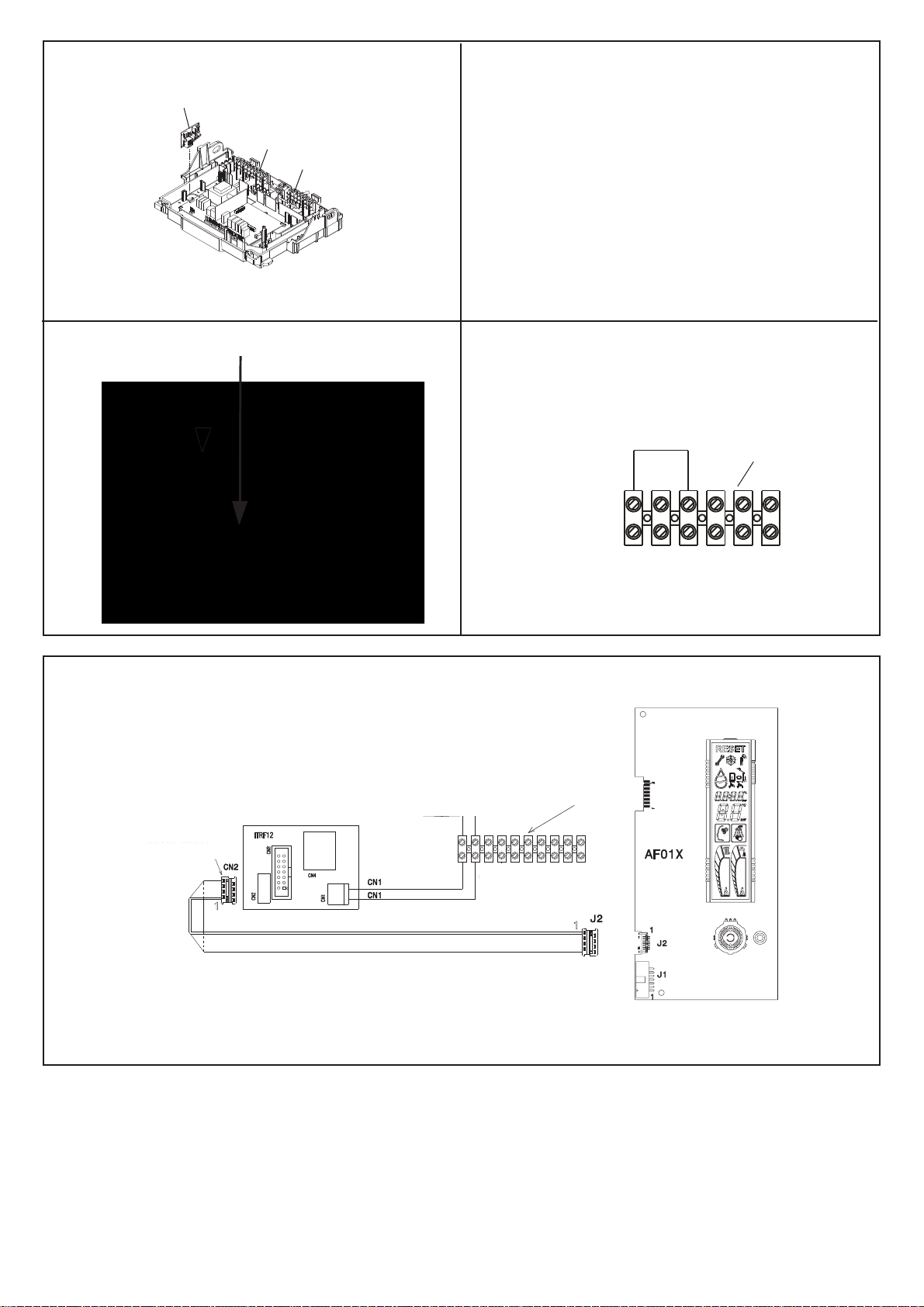
Installazione scheda interfaccia ITFR11
- Installare la scheda ITRF11 all’interno del cruscotto nella posi-
zione indicata in fig. 6
- Prendere la banda piatta proveniente dalla scheda display e
collegare il connettore, evidenziato con una striscia colorata, al
connettore della scheda interfaccia ITRF11 (fig. 7)
- Collegare il cablaggio fornito in dotazione dal morsetto CN1 della
scheda interfaccia (fig. 8) ai morsetti 1 e 2 della morsettiera di
bassa tensione 10 poli (M10) della caldaia (fig. 10)
- Collegareaidue terminali il segnale OPERNTHERM proveniente
dall’esterno (N.B. la polarità è indifferente)
- Togliere il cavallotto del T.A. sulla morsettiera 6 poli M6/ME1
(fig. 9).
- Chiuderei coperchiettidiprotezionemorsettierafacendoli scorrere
nel senso indicato dalla freccia e avvitare le viti precedentemente
rimosse
- Chiudere il cruscotto, rimontare copertura e mantello.
Alla successiva riaccensionedel sistema, metterel’interfaccia
AF in Remote premendo il tasto (Local/Remote) presente
sulla stessa.
C
sepresente
fig. 1 fig. 2
fig. 3
fig. 4
fig. 5
INSTALLINGTHE REMOTE CONTROL
INTERFACE ITRF11
1) If the ITRF12 remote control interface is already installed in the
boiler control panel, replace it with the ITRF11 interface and
make the same electrical wiring operations
2) If the ITRF12 remote control interface is not installed in the
boiler control panel, proceed as follows:
Before performing any operation, switch off the power supply of
the boiler by turning the general system and main boiler switches
to“OFF”.In order to have access to the control panel of the boiler,
proceed as follows:
- unscrew the fixing screws (C fig. 1) of the connections cover
- take out the connections cover by pulling it towards you (A-B
fig. 2)
- unscrew the fixing screws (D fig. 3) of the appliance casing
- move forward and then upwards the lower part of the appliance
casing in order to unhook it from the template (fig. 4)
- lift the control panel and successively turn it forward
- unscrew the fixing screws of the terminal board covers, then
open them by sliding them in the direction shown by the arrows
(fig. 5).
Installing the remote control interface ITRF11
- Fit the remote control interface in the control panel, in the posi-
tion shown in fig.6
- Take the flat band from the display card and connect the con-
nector (highlighted with a coloured strip) to the ITRF11 interfa-
ce card connector (fig. 7)
- Connect the wiring (supplied) from clamp CN1 of the remote
control interface (fig. 8) to clamps 1 and 2 of the 10-pole low
voltage terminal board (M10) of the boiler (fig. 10)
- Connect the external OPEN THERM signal to the two termi-
nals (NB: the polarity is not important)
- Remove the R.T. U-bolt from the 6-pole M6/ME1 terminal
board
- Close the terminal board protection covers by sliding them in
the direction shown by the arrow, then replace and tighten the
screws
- Close the control panel and reassemble the cover and the ap-
pliance casing.
At the next system switch-on, put the AF interface in Remote by
(fig. 9).
FAMILY BOILERS TYPE