Miura CONNECT User manual

MIURA CONNECT
INSTALLATION MANUAL
INFORMATION IN THIS MANUAL MAY BE CHANGED WITHOUT ANY NOTICE.
Please ensure that installation manual is read and observed in full by all persons working with the product. Please
also ensure that it is stored in a location where it may be easily accessed by said persons.
Document Number: EN-MN-006-01-iii
Date Issued: 03/10/2022

Document No.: EN-MN-006-01-iii
Page 2 of 21
This Installation Manual explains the transport and installation of Miura Connect. Carefully read this Installation
Manual and understand the contents before installing. Particularly important points are denoted as DANGER,
WARNING, CAUTION, and NOTE in descending order of severity.
Indicates an imminently dangerous situation which leads to serious injury or
death to the user if the product is mishandled.
Indicates a situation which might cause serious injury or death to the user if
the product is mishandled.
Indicates a situation which might cause minor injury to the user or the
occurrence of physical damage only if the product is mishandled.
Describes the precautions to prevent failures of the product, points to perform
effective operation, and useful information to know.
DANGER
WARNING
CAUTION
NOTE

Document No.: EN-MN-006-01-iii
Page 3 of 21
When installing and using this product, you are obligated to submit official notification, and to install, construct, and utilize
the product in compliance with applicable laws and regulations. For the product to be used safely and reliably, it is crucial
that, in addition to fulfilling these legal obligations, you also establish and implement a safety management system.
This section highlights situations where failure to follow the guidelines could lead to serious injury or death.
(1) Relocation and Resale
If you intend to relocate or sell your MIURA product, contact your dealer or
MIURA sales office in order that installation work can be carried out correctly
and that the required peripheral equipment may be set up. In addition, ensure
that manuals and the like are kept in order that they may also be provided to
the new owner in the event of resale.
(2) Prohibition of Modification without Permission
Customization or modification not recommended by MIURA may present safety
problems and is therefore prohibited. If you wish to modify the product, contact
your dealer or MIURA sales office in advance. It should be noted that MIURA
will accept no responsibility for the outcome of unapproved customization.
(3) Electrical Work
When connecting a power supply to the product, use wire of the specified
diameter and ensure that the product is correctly grounded. Furthermore, a
dedicated power supply must be used, and a ground fault circuit breaker (with
overcurrent protection) must be installed.
If this precaution is not observed, serious accidents such as electric shock and
the outbreak of fire may result.
(1) Product Installation
Ensure that installation work is carried out correctly as set forth in the applicable MIURA Installation Manual.
Furthermore, anybody who will work with the product should carefully study the content of the Operation Manual in
advance and ensure that it is fully understood.
Precautions for installation and use — Related laws and regulations
1) The table below shows part of the laws and regulations on installation and use. There are also prefectural and
municipal ordinances; therefore, contact the supervisory authority or competent authority for more information.
2) The details herein are based on the regulatory standards at the time of preparation.
3) The documents to be submitted and their destination vary depending on your equipment and facilities.
If you have any questions, contact your dealer, Miura sales office, or the competent supervisory authority.
Related laws and
regulations
Form(s) to be
submitted
Destination
Submission
timing
Remarks
NEC
Customer Intake
Forms
MiuraConnect@
miuraz.com
Before
startup
This form allows MIURA to configure
the online dashboard for the specific
installation site.
アース端子
Ground
terminal
NOTE

Document No.: EN-MN-006-01-iii
Page 4 of 21
Table of Contents
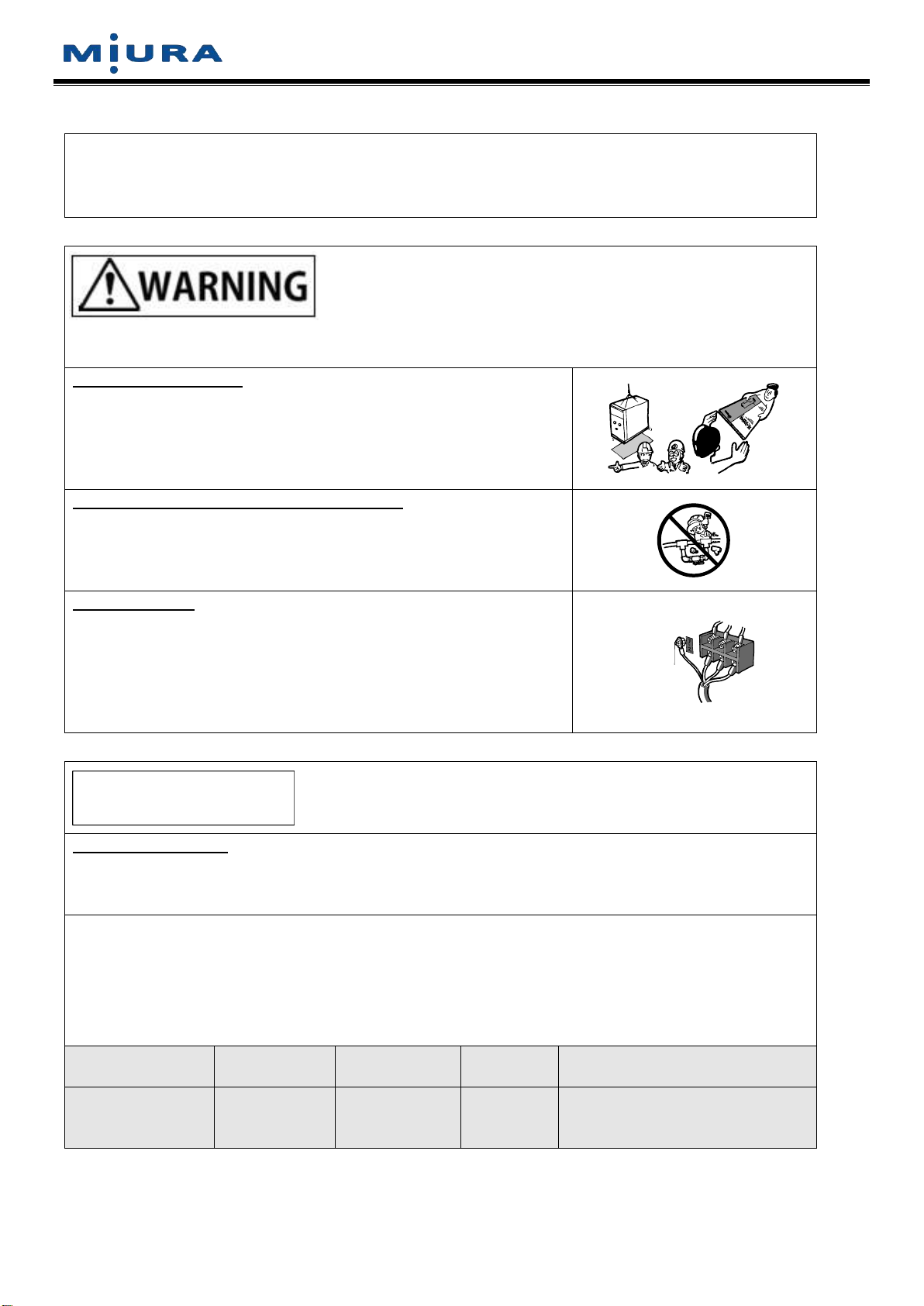
1. Precautions Regarding Installation.....................................................................................................5
2. Specifications ........................................................................................................................................6
2.1. Introduction.......................................................................................................................................6
2.2. Specifications ...................................................................................................................................7
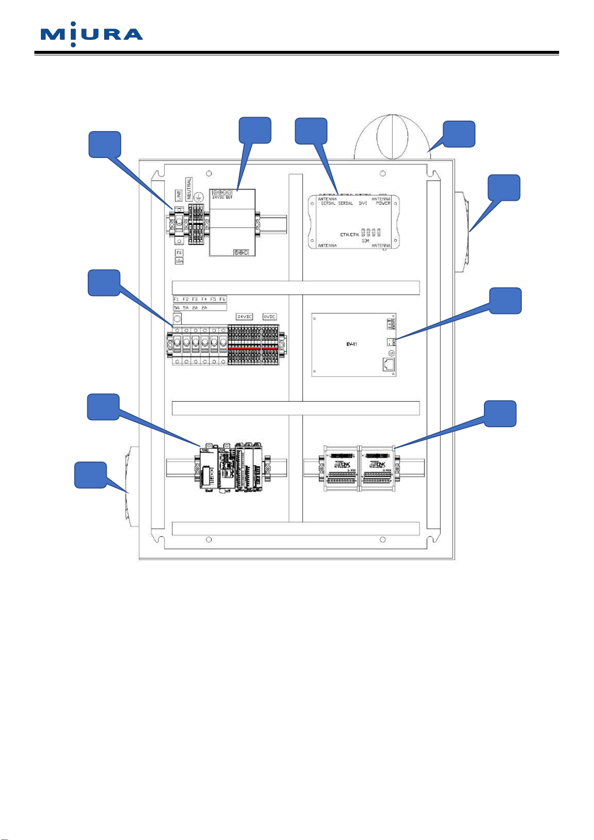
2.3. Internal System Configuration..........................................................................................................8
3. Mounting the Panel ...............................................................................................................................9
3.1. Precautions when Installing the Main Unit.......................................................................................9
3.2. Installation Procedures...................................................................................................................10
4. Field Wiring ..........................................................................................................................................10
4.1. Wiring Power Supply and Installing Ground Fault Circuit Breaker ................................................10
4.2. Wiring Communication Lines .........................................................................................................10
4.3. Antenna .......................................................................................................................................... 11
4.4. (Optional) PLC – Thermocouples ..................................................................................................12
4.5. (Optional) PLC – Discrete Inputs (dry contacts) ............................................................................12
4.6. (Optional) PLC – Analog Inputs (see next section for pressure transducer wiring) ......................13
4.7. (Optional) PLC – Analog Input – Yokogawa Pressure Transducer Input.......................................14
4.8. (Optional) PLC – Analog Input – Johnson Controls Pressure Transducer Input...........................15
5. Device Settings ....................................................................................................................................16
5.1. EV-11 COM Settings (board inside Miura Connect panel) ............................................................16
5.2. EJ-210 Settings (communication board inside each boiler control panel) ....................................16
6. Modbus TCP Output (Optional)..........................................................................................................17
7. Startup ..................................................................................................................................................17
7.1. Boiler Room Setup on www.Miura-Connect.com...........................................................................17
7.2. SIM Card Installation......................................................................................................................17
7.3. Change Modbus IP Address at Startup..........................................................................................18
7.4. Connect to a Wi-Fi Network at Startup ..........................................................................................18
7.5. Change the PLC Program at Startup.............................................................................................19
8. Serial Number Explanations...............................................................................................................20
9. Spare Parts...........................................................................................................................................21

Document No.: EN-MN-006-01-iii
Page 5 of 21
1. Precautions Regarding Installation
When installing the equipment and performing the instrumentation work, take due care of the following
precautions.
1. When performing the grounding work, connect the ground wire to the ground terminal inside the panel.
Use wire with a diameter equal to or larger than the power supply wire (AWG-14).
2. Do not install an overcurrent circuit breaker in the grounding wire.
3. Install a ground fault circuit breaker with over-current protection or independent devices to protect against
short circuits, overloads, and grounds faults within 10 ft (3 m) of the node point in the low-voltage interior
wiring.
Circuit breaker capacity
[A]
Rated sensitivity current
[mA]
15
30
4. Use a power supply wire with insulation resistance of 0.1 MΩ or higher.
5. Use AWG-14 or larger diameter for the power line. Protect the wire in a conduit.
6. Use a 100 m (330 ft) or shorter Cat 5 cables to connect equipment
7. Install power supply wires and communication wires separately.

Document No.: EN-MN-006-01-iii
Page 6 of 21
2. Specifications
2.1. Introduction
Miura Connect natively monitors select Miura equipment via the M-NET3 network. Monitored equipment includes
BL11-based boilers, MW water softeners, and Colormetry units. Note that appropriate equipment as listed below
is required to connect equipment to the M-NET3 network
Boilers
•Single or multiple: EG11, order SPO31-03
•Multiple: EJ-210, order SPO27-02
Water Treatments Devices
Water treatment devices communicate via DS-NET network which must be converted with a card included in the
following products. Note, only one card is necessary per installation.
•WP2-200, water treatment control panel
•BP-201, multiple boiler controller
•EN-011A, network hub with DS-NET to M-NET3 converter
•EN-021A, network hub with optical port and DS-NET to M-NET3 converter
There must be an open port within the M-NET3 network for connection to the Miura Connect panel. If there are no
open ports, an EN-type expansion panel should be ordered.
External Equipment (optional)
Miscellaneous sensors can be monitored via connection to the Miura Connect panel’s open PLC inputs. PLC
inputs can be mapped to custom equipment assets on the web dashboard. For example, various signal outputs
from a third-party feed tank can be connected to the PLC and mapped to a custom feed tank asset on the web
dashboard. Miura Connect uses Automation Direct Productivity1000 PLC components.
NOTE

Document No.: EN-MN-006-01-iii
Page 7 of 21
2.2. Specifications
Communication wire standard
Category 5 shielded cable or better with RJ45 connector
Maximum connection distance
330’ (100 m)
Operating temperature
32F–120F
Operating humidity
30–85% (no condensation and freezing)
Power supply
120 VAC, 50/60 Hz, single-phase
Power consumption
600 VA (max.)
Full load current
5 A
Max. short circuit current
100 kA
Product mass
100 lbs
Overall dimensions
30” (H) x 24” (W) × 10” (D)
Discrete inputs
(16) 24VDC sinking/sourcing, 8 points per common
Thermocouple inputs
(4)
Analog signal inputs
(8) 4-20mA
Data connection
Wired Internet, Wi-Fi, and/or Cell Service

Document No.: EN-MN-006-01-iii
Page 8 of 21
2.3. Internal System Configuration
A. 120VAC and ground landing terminals
B. 24VDC power supply
C. Industrial PC
D. Antenna
E. Exhaust fan
F. Component fuses, 24VDC and common terminals
G. EV-11
H. PLC
I. PLC terminals
J. Filter
A
B
F
G
D
E
J
H
I
C

Document No.: EN-MN-006-01-iii
Page 9 of 21
3. Mounting the Panel
3.1. Precautions when Installing the Main Unit
•Install in a location within the equipment operating environment range (temperature and humidity).
•Avoid the following locations, which may cause equipment failure.
oLocations subject to direct sunlight or near equipment that generates excessive heat
oHot locations or locations with large temperature fluctuations
oLocations with high levels of moisture or dust
oLocations subject to shocks or vibrations
oLocations in a chemical atmosphere, or locations that may contact chemicals or water
oLocations near power lines or near equipment that generates strong magnetic fields
oLocations subject to severe supply voltage fluctuations
•Firmly fix the panel in a location that is free of vibrations.
•Install in a location free of water and condensation.
•Ensure adequate space to open the door for maintenance work.
•During installation, do not touch any of the internal circuit boards. Do not allow dust or metal fragments to
enter inside the main unit.
•The product is designed for indoor installation. When installing outdoors, take appropriate measures to
protect against water, dust, and freezing, and select a location that is not subject to direct sunlight.
CAUTION
Observe the following precautions about installation and ensure that
the product is installed in an appropriate location. Installation in an
inappropriate location may result in equipment failure.
CAUTION
Do not directly weld the box onto a column or wall. The product
contains electrical equipment that may be damaged by the effects of
arc welding.

Document No.: EN-MN-006-01-iii
Page 10 of 21
3.2. Installation Procedures
•Utilize the existing anchor holes in the back of the panel to affix the equipment to a wall, etc.
•Ensure the anchor location can withstand the load
4. Field Wiring
4.1. Wiring Power Supply and Installing Ground Fault Circuit Breaker
•Route power supply and ground conductors through the left wire ducted intended for 120VAC
•Use AWG-14 or larger diameter for the power line. Protect the wire in a conduit.
•Ground the equipment using a wire of the same or larger diameter than the power supply wire.
•Install a ground fault circuit breaker with over-current protection in the power supply line.
4.2. Wiring Communication Lines
•Route communication lines through the right wire duct intended for communication signals
•Separate the communication wires from power wires and power supply wires and do not pass them
through the same conduit.
•Do not pass wires next to high-output equipment that generates strong electrical or magnetic fields.
•Do not use communication wires made by joining multiple wires.
•If wires are passed near parts that generate heat of 120F or higher (such as steam piping and boiler main
unit), insulate the communication wires from the hot surfaces so the temperature around the wires remains
less than 120F.
•Be cautious when handling wires so as not to cause damage.
•When using a cable protector such as a conduit and metal flexible tube, select a protector with an
appropriate size to prevent pressure from being applied to communication wires inside the protector.

Document No.: EN-MN-006-01-iii
Page 11 of 21
4.3. Antenna
•Cellular and Wi-Fi connections require an antenna
•The antenna may be mounted remotely when necessary for increased signal strength
•The antenna includes (2) wires for cellular connection and (2) wires for Wi-Fi connection
One pair of connectors is male
while the other is female. Check
the gateway terminals to ensure
cables are connected to the
correct ports. The connectors
within a pair are identical and can
connect to the corresponding ports
on the gateway in any order.
Male and Female Connectors
2G/3G/4G
2.4/5GHz
INTERNET
(OPTIONAL)
M-NET3 MIURA
NETWORK
LAN 1 Port
LAN 2 Port
MODBUS TCP
(OPTIONAL)
2G/3G/4G
2.4/5GHz
#1
#1
NOTE

Document No.: EN-MN-006-01-iii
Page 12 of 21
4.4. (Optional) PLC – Thermocouples
•Wire thermocouples directly to the PLC card ensuring that polarity is correct
•Thermocouple type is set as K by default. Consult the factory if an alternate type is desired.
4.5. (Optional) PLC – Discrete Inputs (dry contacts)
•Connect external dry contacts as shown between 24VDC and Zip-Link terminals while referencing the
terminal labels
24VDC
DISCRETE INPUTS
EXTERNAL SWITCH

Document No.: EN-MN-006-01-iii
Page 13 of 21
4.6. (Optional) PLC – Analog Inputs (see next section for pressure transducer wiring)
•Connection details depend on the specific analog device you are connecting, see examples below
•Connect analog inputs to the Zip-Link terminals while referencing the terminal labels
•2 and 3-wire devices should be powered from the Miura Connect panel’s 24VDC supply
•Devices must be scaled correctly within the PLC program. Consult the factory for support
4-20mA Terminals

Document No.: EN-MN-006-01-iii
Page 14 of 21
4.7. (Optional) PLC – Analog Input – Yokogawa Pressure Transducer Input
•Follow the diagram below when connecting the Yokogawa pressure transducer
•Device must be scaled correctly within the PLC program. Consult the factory for support
1
2
E

Document No.: EN-MN-006-01-iii
Page 15 of 21
4.8. (Optional) PLC – Analog Input – Johnson Controls Pressure Transducer Input
•Follow the diagram below when connecting the Johnson Controls pressure transducer
•Device must be scaled correctly within the PLC program. Consult the factory for support
red
black
shield
White
(isolate and insulate)

Document No.: EN-MN-006-01-iii
Page 16 of 21
5. Device Settings
The following settings must be made for Miura Connect to function properly.
Do not adjust settings while equipment is powered
5.1. EV-11 COM Settings (board inside Miura Connect panel)
•Confirm function switch 1 is set to ON and network ID is set to 95 or similar, unused ID number
•Note: setting switches 6 and 7 ON will place the board in simulation mode which will generate test data
5.2. EJ-210 Settings (communication board inside each boiler control panel)
•First follow standard EJ-210 startup and BP-201 procedures and confirm boiler system is controlling
correctly.
•Set function switch 1, 3, and 4 to ON.
oNote, do not adjust other switch positions, only confirm 1, 3, and 4 are ON
↓
Initialize FunctionNET_No.
ON
1 2 0
5
9
1
2
3
4
8
7
6
↓
0
5
9
1
2
3
4
8
7
6
ON ON
1 2 13 2 3 4 5 6 7
ID_No.
×10 ×1
NOTE

Document No.: EN-MN-006-01-iii
Page 17 of 21
6. Modbus TCP Output (Optional)
•The Miura Connect PC functions as a Modbus slave and can output all collected data via LAN 2 port
•Default settings are:
•See the following pages for instructions on changing these settings
•Reference the “Miura Connect Modbus Registers” for a complete signal list
7. Startup
7.1. Boiler Room Setup on www.Miura-Connect.com
•Miura must setup the boiler room on the web interface before data can be accessed. To facilitate this,
submit a request to miuraconn[email protected] or complete these forms
ohttps://app.smartsheet.com/b/form/1a80b569d79d45f28ca674cb54aa3ed9
ohttps://app.smartsheet.com/b/form/49438e1172a44db4bb959a5036a345e2
•Miura Connect automatically recognizes Miura equipment (Boiler, CMU, MW) and the PLC via serial
numbers, so you must provide serial numbers to complete the installation
•PLC inputs are freely assignable, so you must provide specific signal details to complete the installation
•PLC inputs, specifically thermocouple and analog signals, may require a custom PLC program to function
as you desire. The program can be modified in the field if needed and the software is free to use.
7.2. SIM Card Installation
•Inform Miura of the 18~22-digit SIM card number so it may be activated; the number is printed on the
actual SIM card
•Punch out the SIM card at the largest size and insert into the gateway with microchip facing down
IP: 10.0.0.102
Gateway: 10.0.0.1
Netmask: 255.255.255.0
LAN 2 Port

Document No.: EN-MN-006-01-iii
Page 18 of 21
7.3. Change Modbus IP Address at Startup
•To change the Modbus address in the field, submit a request to miuracon[email protected] including the
required IP address and gateway or use this form
ohttps://app.smartsheet.com/b/form/49438e1172a44db4bb959a5036a345e2
•Miura will either ship a ready-to-use USB flash drive or electronically deliver a custom “config.json” file
you must place on your own USB flash drive
oIf you are providing your own USB flash drive, name the device “MIURA_CFG” and ensure it is
blank except for the custom file
•With the gateway running, insert the USB flash drive into the gateway, wait one minute, then remove the
USB flash drive
•The gateway will now have the new Modbus settings upon reboot
7.4. Connect to a Wi-Fi Network at Startup
•To connect to a Wi-Fi network in the field you may follow these steps directly or submit a request to
miuraconnect@miuraz.com for support
With Miura support
•Miura will either ship a ready-to-use USB flash drive or electronically deliver a custom “wifi.txt” file you
must place on your own USB flash drive
oIf you are providing your own USB flash drive, name the device “MIURA_CFG” and ensure it is
blank except for the custom file
On your own
•Prepare a blank USB flash drive named “MIURA_CFG”
•Open a word processor program capable of creating a .txt file, such as Notepad, and add the following
text. Replace “Network Name” and “Password” with your specific network details
•Save the file as “wifi.txt” onto the USB flash drive
At the gateway
•With the gateway running, insert the USB flash drive into the gateway, wait one minute, then remove the
USB flash drive
•The gateway will now have the new Wi-Fi settings upon reboot
{
“version”: “v1.0.0”,
“ssid”: “Network Name”,
“password”: “Password”
}

Document No.: EN-MN-006-01-iii
Page 19 of 21
7.5. Change the PLC Program at Startup
•When a custom PLC program is required, you may modify the existing program directly or submit a
request to miuraconnect@miuraz.com for support
•Install the latest version of Automation Direct Productivity Suite software which is freely available
•Ensure the PLC is powered on, and the toggle switch is set to RUN
•Connect your PC to the PLC with a Micro-B USB cable
With Miura support
•Miura will provide a custom program, open this program within the Productivity Suite software
•With physical connection established with USB cable, connect to the PLC from the software
oClick “CPU > Online” from the main toolbar, select the device shown in the table, click “Connect”
oIf prompted to copy the project from the CPU or use PC project, chose “No, Use PC Project”
•Transfer the custom program by clicking “File > Transfer Project > To CPU…”
•Disconnect from the PLC by choosing “Offline”
On your own
•Follow similar steps as above to connect to the PLC from the software, but in this case, you want to read
the existing program from the PLC so it can be modified
•Be sure to save a copy of the original program before making modifications.
•Note the variable types and Modbus registers should not be changed for existing tags

Document No.: EN-MN-006-01-iii
Page 20 of 21
8. Serial Number Explanations
Panel Serial Number – labeled during panel production:
MC-101-##-YYMMDD
Note: 101 indicates panel design version and will change over time
PLC Serial Number – programed by Engineering to match panel serial number:
MC-PLC-##-YYMMDD
Gateway Client ID – programed by Engineering to match panel serial number:
mcsite_##YYMMDD
Note: client id MUST start with “mcsite_” for the cloud service to recognize it as a gateway
SIM Card Name – labeled by Support during startup to match panel serial number:
mcsite_##YYMMDD (SIM#)
Note: should match gateway client ID (mcsite_##YYMMDD) for ease of troubleshooting.
Table of contents
Other Miura Boiler Supplies manuals

Miura
Miura CMU-324HE User manual

Miura
Miura Comm-Link User manual

Miura
Miura BP-201 User manual

Miura
Miura EJ-210 User manual

Miura
Miura BP-201 Troubleshooting guide

Miura
Miura MP1-200 User manual

Miura
Miura CMU-324HE User manual

Miura
Miura WP2-200A User manual

Miura
Miura WP2-200A User manual

Miura
Miura STEAM EO-010A User manual