Fröling Lambdatronic S 3200 User manual

Service manual
Lambdatronic S 3200 for firewood boiler
Core module version 50.04 - Build 05.20 | Touch control version 60.01 - Build 01.38
Translation of the original German installation instructions for technicians
Read and follow the instructions and safety information!
Technical changes, typographical errors and omissions reserved!
B1420922_en | Edition 27/10/2022
Froling GesmbH | A-4710 Grieskirchen, Industriestraße 12 | www.froeling.com

1 General 4
1.1 About these instructions 4
1.2 Safety information 4
2 Power connection and wiring 5
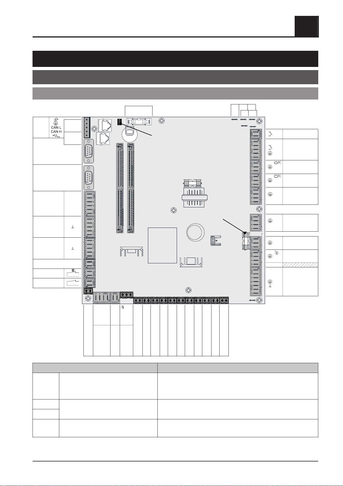
2.1 Core module and connection options 5
2.1.1 Board view - core module 5
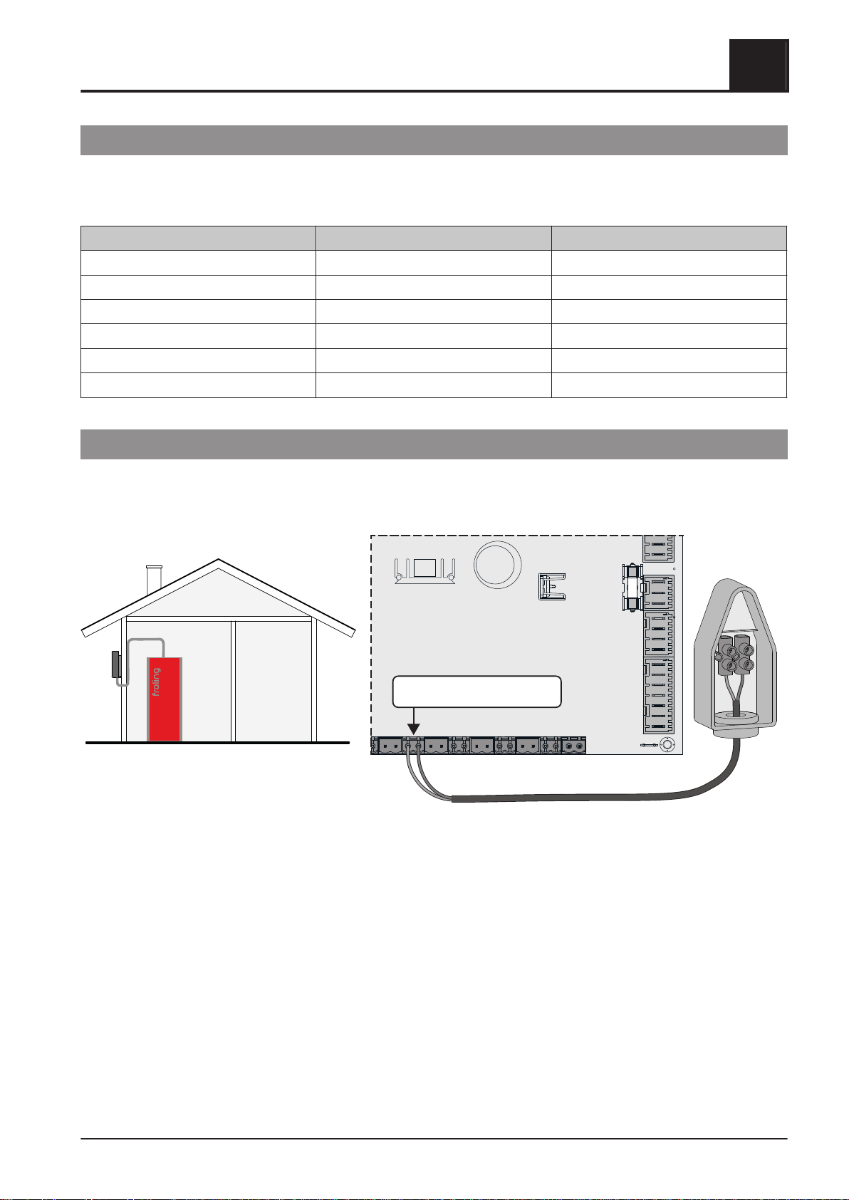
2.1.2 Mains connection 9
2.1.3 Connecting the outside temperature
sensor
9
2.1.4 FRA room temperature sensor 10
2.1.5 Connecting a circulating pump to the core
module
11
2.1.6 Connecting an isolating valve to the core
module
13
2.1.7 Heating circuit pump 0 / burner relay 14
2.1.8 Operating signal 14
2.2 Expansion modules 15
2.2.1 Heating circuit module 15
2.2.2 Hydraulic module 16
Connecting a circulating pump to the hydraulic
module
18
Connecting an isolating valve to the hydraulic
module
21
2.2.3 Return mixer module 22
2.2.4 Ignition expansion 23
2.2.5 Analogue module 25
External power demand
26
24 V power supply
26
2.3 BUS connection 27
2.3.1 Connecting the bus cable 28
2.3.2 Setting end jumpers 28
2.3.3 Setting the module address 29
2.3.4 Potential equalisation / potential
separation
30
2.4 Connection information according to
pump types
31
3 Initial start-up with settings wizards 32
3.1 Before switching on for the first time 32
3.1.1 Controller check 32
3.1.2 Check on the connected units 32
3.1.3 System check 32
3.2 General information about the settings
wizard
33
3.3 Switching on for the first time 34
3.4 Starting the setting wizard 35
4 Parameters overview 37
4.1 Heating 37
4.1.1 Heating - Status 37
4.1.2 Heating – Temperatures 38
4.1.3 Heating - Times 39
4.1.4 Heating - Service 39
4.1.5 Heating - Heating up program 40
Heating up programs
41
Configure program 8
41
Heating circuits used
41
4.1.6 Heating - General settings 42
4.2 Water 43
4.2.1 Water - Status 43
4.2.2 Water - Temperatures 43
4.2.3 Water - Times 44
4.2.4 Water - Service 44
4.3 Solar 45
4.3.1 Solar - Status 45
4.3.2 Solar - Temperatures 46
4.3.3 Solar - Times 47
4.3.4 Solar - Service 47
4.3.5 Solar - Heat meter 49
4.4 Buffer tank 50
4.4.1 Buffer tank - Status 50
4.4.2 Buffer tank - Temperatures 51
4.4.3 Buffer tank - Service 52
4.5 Boiler 53
4.5.1 Boiler - Status 53
4.5.2 Boiler - Temperatures 54
4.5.3 Boiler - Service 54
4.5.4 Boiler - General settings 55
Boiler - General settings - MODBUS settings
56
Boiler - General settings - Operator data
57
4.6 Boiler 2 57
4.6.1 Boiler 2 - Status 57
4.6.2 Boiler 2 - Temperatures 58
4.6.3 Boiler 2 - Service 59
4.7 Ignition 60
4.8 Fuel 61
4.9 Network pump 62
4.9.1 Network pump - Status 62
4.9.2 Network pump - Temperatures 62
4.9.3 Network pump - Service 63
4.10 Difference regulator 64
Table of contents
2 Froling GesmbH | A-4710 Grieskirchen, Industriestraße 12 | www.froeling.com

4.10.1 Difference regulator - Status 64
4.10.2 Difference regulator - Temperatures 64
4.10.3 Difference regulator - Times 65
4.10.4 Difference regulator - Service 65
4.11 Circulation pump 66
4.11.1 Circulation pump - Status 66
4.11.2 Circulation pump - Temperatures 66
4.11.3 Circulation pump - Times 67
4.11.4 Circulation pump - Service 67
4.12 Manual 68
4.12.1 Manual - Manual operation 68
4.12.2 Manual - Digital outputs 68
4.12.3 Manual - Analogue outputs 69
4.12.4 Manual - Digital inputs 70
4.13 System 71
4.13.1 System - Settings 71
Setting - Boiler temperature
71
Setting - Flue gas
71
Setting - Ignition
72
Setting - Air settings
73
Setting - Lambda values
74
Set - Lambda probe
74
Set - Quantity of heat calculation
76
Setting - General settings
77
4.13.2 System - Current values 78
4.13.3 System - Sensors and pumps 78
4.13.4 System - System selection 78
4.14 Diagnostics 79
4.14.1 Diagnosis – Current fault list 79
4.14.2 Diagnosis – Clear pending error 79
4.14.3 Diagnostics - Error history 79
4.14.4 Diagnostics - Clear error history 80
4.15 Touchscreen 81
4.15.1 Touchscreen - Display settings 81
Display settings - General
81
Display settings - Basic display
82
Display settings - Date / Time
82
Display settings - Software update / Service
82
4.15.2 Touchscreen - Display operating rights 83
Froling Connect
83
4.15.3 Touchscreen - Display allocation 84
5 FAQ 85
5.1 Activation options of pump outlets 85
5.2 Pump stall protection 86
5.3 Boiler operating statuses 87
5.4 Determination of the quantity of heat 88
5.4.1 Assembly Information 88
5.4.2 Functioning and configuration 88
Calculating the feed output of the circulating pump
88
Setting the type of heat quantity calculation
90
Configuring the heat quantity calculation
90
5.5 Setting times 91
5.6 Calibrating the touchscreen 93
5.7 Software update Lambdatronic 3200 95
5.7.1 Carrying out a software update on the
boiler controller
96
5.7.2 Carrying out a software update on the
touch control
98
5.7.3 Finishing a software update 99
5.8 USB data recording 100
6 Notes 102
7 Appendix 104
7.1 Addresses 104
7.1.1 Address of manufacturer 104
Customer service
104
7.1.2 Address of the installer 104
Table of contents
Service manual Lambdatronic S 3200 for firewood boiler | B1420922_en 3

1 General
1.1 About these instructions
Please read and follow the operating instructions, in particular the safety information contained therein. Keep
them available next to the boiler.
These operating instructions include important information about operation, electrical connection and
troubleshooting. The parameters shown depend on the set boiler type and the system configuration!
The constant further development of our products means that there may be minor differences from the pictures
and content. If you discover any errors, please let us know: [email protected].
1.2 Safety information
DANGER
When working on electrical components:
Risk of electrocution!
When work is carried out on electrical components:
❒ Always have work carried out by a qualified electrician
❒ Observe the applicable standards and regulations
➥Work must not be carried out on electrical components by unauthorised persons
WARNING
When touching hot surfaces:
Severe burns are possible on hot surfaces and the flue gas pipe!
When work is carried out on the boiler:
❒ Shut down the boiler according to procedure (“Off” operating status) and allow it to cool
down
❒ Protective gloves must usually be worn for work on the boiler, and it should only be
operated using the handles provided
❒ Insulate the flue gas pipes and do not touch them during operation
The information on safety, standards and guidelines in the assembly and operating instructions for the boiler
should also be observed!
1General
About these instructions
4 Froling GesmbH | A-4710 Grieskirchen, Industriestraße 12 | www.froeling.com

2 Power connection and wiring
2.1 Core module and connection options
2.1.1 Board view - core module
6,3 AT
sw +
gr -
IN
+24V
grün-gelb
rot +
blau -
ws 13VDC
NZ
COM
PZ
S
HE-
HE+
ZU
AUF
P2
5V/P3
ZU
AUF
P2
5V/P3
ws 13VDC
KM-35
(Betriebssignal)
KM-02
(Bus)
KM-01
(Bus)
KM-04
(COM 2)
KM-06
(Breitbandsonde)
KM-09
(Verriegelung)
KM-10
(STB)
KM-11
(NOT-HALT)
KM-07
(siehe Tabelle ...)
KM-08
(siehe Tabelle ...)
KM-05
(COM 1)
KM-03
(Bus)
KM-36
(Optionsmodul) L N
PEPEPE
KM-34
(Heizkreispumpe 0
oder Brennerrelais)
KM-33
(Heizkreispumpe 1)
KM-32
(Heizkreispumpe 2)
KM-31
(Mischer 1)
KM-30
(Mischer 2)
KM-29
(Netz)
KM-28
(Pumpe 1)
KM-27
(Saugzug)
FRKEM29
L1
N
N
L
N
L
N
L
N
LV
LV
L
Sig
+5V
N
L
N
AUF
ZU
N
AUF
ZU
KM-26 (PWM / 0-10V Pumpe 1)
KM-25 (Kesselfühler)
KM-24 (Rücklauffühler)
KM-23 (Vorlauffühler 1)
KM-22 (Vorlauffühler 2)
KM-21 (Raumfühler 1)
KM-20 (Raumfühler 2)
KM-19 (Außenfühler)
KM-18 (Fühler 1)
KM-17 (Fühler 2)
KM-16 (Türkontaktschalter)
KM-15
(Abgasfühler)
KM-14
(Kesselfreigabe)
KM-13
(Lambdasonde)
KM-12 (Durchflussmesser)
End jumper
Mains fuse
Core module
Connection / Name Note
KM-01 BUS Connection with cable – LIYCY paired 2x2x0.5;
⇨ See "Connecting the bus cable" [page 28]
Caution! CAN L and CAN H must not be connected to +UBUS!
KM-02 BUS Patch cable CAT 5 RJ45 SFTP 1:1 configuration; pellet module
connection
KM-03
KM-04 COM 2 Null modem cable 9-pin SUB-D;
Connection is used e.g. as MODBUS interface
Power connection and wiring 2
Core module and connection options
Service manual Lambdatronic S 3200 for firewood boiler | B1420922_en 5

Connection / Name Note
KM-05 COM 1 Null modem cable 9-pin SUB-D;
Service interface for software update and connection to visualisation
software
KM-06 Broadband probe Connection cable1) 5 x 0.75 mm2
Connection of a Bosch (item number 69001A) or NTK (item number
69003) broadband Lambda probe
KM-07 Secondary air S1 Turbo
S3 Turbo
S4 Turbo
S4e Turbo
Connection cable1) 5 x 0.75 mm2;
S1 Turbo: Combined air damper for primary and secondary air
KM-08 Primary air S3 Turbo
S4 Turbo
S4e Turbo
Connection cable1) 5 x 0.75 mm2
KM-09 Lock Connection cable1) 2 x 0.75 mm2
KM-10 High-limit thermostat
KM-11 EMERGENCY STOP Caution! Do not connect the emergency stop/shutdown switch to the
boiler power supply line. The switch must be a N/C switch and it
must be linked to the 24V safety chain of the STL at this terminal.
KM-12 Flowmeter Connection cable1) 2 x 0.75 mm2
KM-13 Lambda probe Connection cable1) 4 x 0.75 mm²
Connection of a Bosch switching-type sensor (type LSM11) or NTK
switching-type sensor (type OZA685, item number: 69400)
KM-14 Boiler release Connection cable1) 2 x 0.75 mm2
Caution! The connection must be a floating connection.
Boiler enable contact
24 V supply ⇨ See "Analogue module" [page 25]
KM-15 Flue gas temperature sensor Only use connection cable of the component
24 V supply ⇨ See "Analogue module" [page 25]
KM-16 Door switch Connection cable1) 2 x 0.75 mm2
KM-17 Sensor 2 Connection cable1) 2 x 0.75 mm2
KM-18 Sensor 1 Connection cable1) 2 x 0.75 mm2, sensor 1 in the STL housing
KM-19 Outside temperature sensor Connection cable1) 2 x 0.75 mm2, shielded from 25 m cable length
KM-20 Room temperature sensor heating circuit
2
KM-21 Room temperature sensor heating circuit
1
KM-22 Flow temperature sensor heating circuit
2
KM-23 Flow temperature sensor heating circuit
1
KM-24 Return feed sensor Connection cable1) 2 x 0.75 mm2
KM-25 Boiler sensor
KM-26 PDM / 0-10V pump 1
KM-27 Induced draught fan Connection cable1) 3 x 1.5 mm2 for power supply, Connection cable1)
3 x 0.75 mm2 for analysis of current speed
KM-28 Pump 1 Connection cable1) 3 x 1.5 mm2, max. 1.5A / 280W / 230V
2Power connection and wiring
Core module and connection options
6 Froling GesmbH | A-4710 Grieskirchen, Industriestraße 12 | www.froeling.com

Connection / Name Note
KM-29 Mains connection Connection cable1) 3 x 1.5 mm2, fuse provided by customer: C16A
KM-30 Mixing valve heating circuit 2 Connection cable1) 4 x 0.75 mm2, max. 0.15A / 230V
KM-31 Mixing valve heating circuit 1
KM-32 Heating circuit pump 2 Connection cable1) 3 x 1.5 mm2, max. 2.5A
KM-33 Heating circuit pump 1
KM-34 Heating circuit pump 0
or burner relay
Connection cable1) 3 x 1.5 mm2, max. 2A
KM-35 Operating signal Connection cable1) 2 x 0.75 mm2
⇨ See "Operating signal" [page 14]
KM-36 Optional module Ignition expansion connection
1.YMM as per ÖVE-K41-5 or H05VV-F as per DIN VDE 0881-5
Fuses
F2 6.3 AT Pump 1, induced draught fan
Power connection and wiring 2
Core module and connection options
Service manual Lambdatronic S 3200 for firewood boiler | B1420922_en 7

2Power connection and wiring
Core module and connection options
8 Froling GesmbH | A-4710 Grieskirchen, Industriestraße 12 | www.froeling.com

2.1.2 Mains connection
Connect the power supply at the “mains connection" plug
❒ Flexible sheathed cable must be used for the wiring; this must be of the correct size to comply with
applicable regional standards and regulations.
Boiler type Electric fuses Fuse type
S1 Turbo 16A C16A
S1 Turbo F 16A C16A
S3 Turbo 13A C13A
S4 Turbo 16A C16A
S4 Turbo F 16A C16A
S4e Turbo 16A C16A
2.1.3 Connecting the outside temperature sensor
The outside temperature sensor is included with the materials supplied for the boiler and is usually mounted on
an outer wall that is not directly exposed to the sun. It continuously measures the ambient temperature and
forms part of the weather-compensated heating circuit control.
KM-19 / Außenfühler
In the delivered state, the outside temperature sensor is read in by the core module ("KM-19 / outside
temperature sensor" connection). Alternatively, the outside temperature sensor can be connected to an
additional heating circuit module.
⇨ See "Heating circuit module" [page 15]
Power connection and wiring 2
Core module and connection options
Service manual Lambdatronic S 3200 for firewood boiler | B1420922_en 9

2.1.4 FRA room temperature sensor
In addition to recording the current room temperature, the Froling FRA room temperature sensor also has a
handwheel to adjust the required room temperature and a slide switch to set the mode for the heating circuit.
AUS
UHR
NACHT
TAG
FV
RFFV
COM
Raumfühler FRA
RF 1/2
Kernmodul S/P/H 3200
AUS
UHR
NACHT
TAG
FV
RFFV
COM
Raumfühler FRA
RF 1/2
Kernmodul S/P/H 3200
affecting room: not affecting room:
Possible positions of the mode switch:
Boiler off Heating circuit deactivated, only frost protection!
Automatic mode Heating and setback phases according to the set times
Setback mode Ignores the heating phases and continuously controls the
room temperature to the temperature set in setback mode
Party switch Ignores the setback phases and continuously controls the
room temperature to the temperature set in heating mode
Handwheel… Allows you to adjust the temperature by +/- 3°C
IMPORTANT! Refer to the supplied assembly instructions for more detailed explanations on connecting and
operating the FRA room temperature sensor.
2Power connection and wiring
Core module and connection options
10 Froling GesmbH | A-4710 Grieskirchen, Industriestraße 12 | www.froeling.com

2.1.5 Connecting a circulating pump to the core module
Different types of wiring must be implemented depending on the type of pump:
High efficiency pump with control line (PWM / 0-10V)
On high efficiency pumps with an additional wired control line, the speed control is implemented via the
additional connection for the PWM or 0-10V signal.
FRKEM29
Pumpe 1
N
PE
L
LV
N
Netz
PE
L
AO-P1
PWM
0-10V
❒ Connect the power supply for the high efficiency pump to output “Pump 1” of the core module
❒ Connect the PWM cable of the high efficiency pump to the corresponding “PWM / 0-10V” port
➥Make sure that the cables are configured correctly (polarity) in accordance with the connection diagram
of the pump!
❒ Set control of the pump in the relevant menu to “Field pump / PWM” or “Field pump / 0-10V”
Power connection and wiring 2
Core module and connection options
Service manual Lambdatronic S 3200 for firewood boiler | B1420922_en 11

High efficiency pump without control signal
It is not possible to control the speed when using this type of pump. The use of a line regulating valve (e.g.:
Setter balancing valve) is recommended.
FRKEM29
Pumpe 1
N
PE
L
LV
N
Netz
PE
L
AO-P1
22 12
24 14
21 11
A2 A1
❒ Connect pump with relay and RC element isolated from the output
❒ In the relevant menu, set the pump control to “HE pump without control signal”
AC pump without control signal (pulse package control)
On older pumps without a control signal that are not highly efficient, the speed control is implemented via a
pulse package control. Please note that the minimum speed may need to be adjusted on some pumps (default
setting: 30%).
FRKEM29
Pumpe 1
N
PE
L
LV
N
Netz
PE
L
AO-P1
❒ Connect pump to output “Pump 1” of the core module
❒ In the relevant menu, set the pump control to “Pump without control signal”
2Power connection and wiring
Core module and connection options
12 Froling GesmbH | A-4710 Grieskirchen, Industriestraße 12 | www.froeling.com

2.1.6 Connecting an isolating valve to the core module
If an isolating valve is connected to the speed-controlled pump outlet, an RC element must be used.
FRKEM29
Pumpe 1
N
PE
L
LV
N
Netz
PE
L
AO-P1
HKP0
N
PE
L1
❒ Phase (L) for switching the valve and connecting neutral conductor (N) to output “Pump 1” with the RC
element
❒ Phase (L) for continuous supply (switches the valve back to the initial position) at output “HCP0” – connect
terminal “L1”
Power connection and wiring 2
Core module and connection options
Service manual Lambdatronic S 3200 for firewood boiler | B1420922_en 13

2.1.7 Heating circuit pump 0 / burner relay
Depending on the system setting, the connection “Heating circuit pump 0” can be used for heating circuit pump
0 or as a burner relay. The following connection instructions must be observed:
Heating circuit pump 0 Burner relay
HKP 0
N
PE
L1
The pump can be supplied with up to a
max. 2 Ampere directly via the output.
During this process, phase (L1) of the
output is connected to the switch
contact.
HKP 0
N
PE
L1
L NPE
The pump must be supplied externally
with 2 Ampere. Up to max. 5 Ampere,
the floating contact can used to switch
the phase. At above 5 Ampere, the
pump must be isolated with a relay.
HKP 0
N
PE
L1
Wire the floating output contact as an
enabling signal to control the standby
boiler.
2.1.8 Operating signal
On the core module (connection position KM-35), it is possible to issue a floating operating signal. The status is
displayed under the “Standby relay” output in the “Manual” -> “Digital outputs” menu.
Operating status Relay status
Boiler off, standby, fault 0
All other operating statuses (e.g. preparation, heating up, pre-heating, ignition, heating, slumber,
cleaning, shutdown wait 1, shutdown wait 2, etc.)
1
2Power connection and wiring
Core module and connection options
14 Froling GesmbH | A-4710 Grieskirchen, Industriestraße 12 | www.froeling.com

2.2 Expansion modules
2.2.1 Heating circuit module
Two heating circuits can be controlled as standard with the core module.
To add further heating circuits, the heating circuit module boards must be expanded. Expansion can include up
to eight heating circuit modules (address 0 to 7). A total of up to 18 heating circuits can be controlled. It is
important to ensure that the module address is set correctly.
⇨ See "Setting the module address" [page 29]
N
N
L
L
HE-09
(Heizkreispumpe 1)
HE-08
(Netz)
HE-01
HE-02
(2x Bus)
HE-03
(Vorlauffühler 1)
HE-04
(Vorlauffühler 2)
HE-05
(Raumfühler 1)
HE-06
(Raumfühler 2)
HE-07
(Fühler 1)
HE-10
(Heizkreispumpe 2)
HE-11
(Mischer 1)
HE-12
(Mischer 2)
N
L
N
ZU
AUF
N
ZU
AUF
FRHEM19
Heating circuit module
Module address
End jumper
Mains fuse
Connection / Name Note
HE-01 BUS Connection with cable – LIYCY paired 2x2x0.5;
⇨ See "Connecting the bus cable" [page 28]
Caution! CAN L and CAN H must not be connected to +UBUS !
HE-02 BUS
HE-03 Flow temperature sensor 1 Connection cable1) 2 x 0.75 mm2;
HE-04 Flow temperature sensor 2
HE-05 Room temperature sensor 1 Connection cable1) 2 x 0.75 mm2; shielded from 25 m cable length
HE-06 Room temperature sensor 2
HE-07 Sensor 1 Connection cable1) 2 x 0.75 mm2;
Connection of the outside temperature sensor if this is not to be connected to the
core module. The address of the heating circuit module to which the outside
temperature sensor is connected must be set in the “Heating – General settings”
menu.
HE-08 Mains Connection cable1) 3 x 1.5 mm2, fuse 10A
HE-09 Heating circuit pump 1 Connection cable1) 3 x 1.5 mm2, max. 2.5A / 230V / 500W
HE-10 Heating circuit pump 2
HE-11 Mixing valve 1 Connection cable1) 4 x 0.75 mm2, max. 0.15A / 230V
HE-12 Mixing valve 2
1.YMM as per ÖVE-K41-5 or H05VV-F as per DIN VDE 0881-5
Power connection and wiring 2
Expansion modules
Service manual Lambdatronic S 3200 for firewood boiler | B1420922_en 15

Fuses
F1 6.3 AT Mixer 1, mixer 2, heating circuit pump 1, heating
circuit pump 2
2.2.2 Hydraulic module
The hydraulic module makes the connections of sensors and pumps available for the hydraulic components of
the system (storage tank, DHW tank etc.).
When using the S1 Turbo firewood boiler, the S4 Turbo, and the S4e Turbo with the Lambdatronic S 3200
control, a hydraulic module is included in the delivery as standard (address 0). A further seven modules
(addresses 1 to 7) can be retrofitted.
When using the S3 Turbo firewood boiler in conjunction with the S-Tronic Plus or S-Tronic Lambda controller, a
hydraulic module is NOT included in the delivery (the listed configurations are not available in all countries!).
Expansion can include up to eight hydraulic modules (address 0 to 7).
A hydraulic module is included in the delivery as standard (address 0). A further seven modules (addresses 1 to
7) can be retrofitted.
You must ensure that the module address is assigned correctly.
⇨ See "Setting the module address" [page 29]
Hydraulic module up to version FRHYU21
FRHYU21
N
N
L
L
HY-14
(Pumpe _.1)
HY-13
(Netz)
HY-05
(AO-P1)
HY-07
(Fühler _.1)
HY-08
(Fühler _.2)
HY-09
(Fühler _.3)
HY-10
(Fühler _.4)
HY-11
(Fühler _.5)
HY-12
(Fühler _.6)
HY-06
(AO-P2)
HY-15
(Pumpe _.2)
N
L
HY-03 / HY-04
(Bus)
HY-01
HY-02
(Bus)
Hydraulic module
Mains fuse
Module address
End jumper
Connection / Name Note
HY-01 BUS Patch cable CAT 5 RJ45 SFTP 1:1 configuration;
HY-02 BUS
HY-03 BUS Connection with cable – LIYCY paired 2x2x0.5;
⇨ See "Connecting the bus cable" [page 28]
Caution! CAN L and CAN H must not be connected to +UBUS !
HY-04 BUS
HY-05 AO-P1 Connection cable1) 2 x 0.75 mm2
2Power connection and wiring
Expansion modules
16 Froling GesmbH | A-4710 Grieskirchen, Industriestraße 12 | www.froeling.com

Connection / Name Note
HY-06 Connection of the control signal (PDM or 0-10V) of the relevant pump (AO-P1 =
pump 1 of the board)
AO-P2
HY-07
:
HY-12
Sensor _.1
:
Sensor _.6
Connection cable1) 2 x 0.75 mm2, shielded from 25 m cable length
Sensor inputs on the board. The correct sensor designation is determined by the
set module address (0-7).
Example: Module address “2” = sensor 2.1 to sensor 2.6
HY-13 Mains Connection cable1) 3 x 1.5 mm2, fuse 10A
HY-14 Pump _.1 Connection cable1) 3 x 1.5 mm2, max. 1.5A / 230V / 280W
Pump outlets on board. The correct pump designation is determined by the set
module address (0-7).
Example: module address “2” = pump 2.1 and pump 2.2
HY-15 Pump _.2
1.YMM as per ÖVE-K41-5 or H05VV-F as per DIN VDE 0881-5
Hydraulic module starting with version FRHYU22
FRHYU22
N
N
L
L
HY-14
(Pumpe _.1)
HY-13
(Netz)
HY-03 / HY-04
(Bus)
HY-05
(AO-P1)
HY-07
(Fühler _.1)
HY-08
(Fühler _.2)
HY-09
(Fühler _.3)
HY-10
(Fühler _.4)
HY-11
(Fühler _.5)
HY-06
(AO-P2)
HY-12
(Fühler _.6)
HY-01
HY-02
(Bus)
HY-15
(Pumpe _.2)
L
N
L
L
Hydraulic module
Mains fuse
Module address
End jumper
Connection / Name Note
HY-01 BUS Patch cable CAT 5 RJ45 SFTP 1:1 configuration;
HY-02 BUS
HY-03 BUS Connection with cable – LIYCY paired 2x2x0.5;
⇨ See "Connecting the bus cable" [page 28]
Caution! CAN L and CAN H must not be connected to +UBUS !
HY-04 BUS
HY-05 AO-P1 Connection cable1) 2 x 0.75 mm2
Connection of control signal for relevant pump
HY-06 AO-P2
HY-07
:
HY-12
Sensor _.1
:
Sensor _.6
Connection cable1) 2 x 0.75 mm2, shielded from 25 m cable length
Sensor inputs on the board. The correct sensor designation is determined by the
set module address (0-7).
Example: Module address “2” = sensor 2.1 to sensor 2.6
HY-13 Mains Connection cable1) 3 x 1.5 mm2, fuse 10A
HY-14 Pump _.1 Connection cable1) 3 x 1.5 mm2, max. 1.5A / 230V / 280W
Power connection and wiring 2
Expansion modules
Service manual Lambdatronic S 3200 for firewood boiler | B1420922_en 17

Connection / Name Note
HY-15 Pump _.2 Pump outlets on board. The correct pump designation is determined by the set
module address (0-7).
Example: module address “2” = pump 2.1 and pump 2.2
Depending on the type of pump, the phase (L) is either connected to the relay
output or triac output.
⇨ See "Connecting a circulating pump to the hydraulic module" [page 18]
1.YMM as per ÖVE-K41-5 or H05VV-F as per DIN VDE 0881-5
Connecting a circulating pump to the hydraulic module
CAUTION! As of module version FRHYU22, one relay output is available at each of the pump outlets in addition
to the triac output. Observe the following connection diagrams to correctly implement the wiring of the circulating
pump.
High efficiency pump with control line (PDM / 0-10V)
On high efficiency pumps with an additional wired control line, the speed control is implemented via the
additional connection for the PDM or 0-10V signal.
up to hydraulic module version FRHYU21 up to hydraulic module version FRHYU22
FRHYU21
N
Pumpe 1Netz
PE
L
N
PE
L
AO-P1
PWM
0-10V
FRHYU22
PWM
0-10V
N
AO-P1
Pumpe 1Netz
PE
L
N
PE
L
L
❒Hydraulic module FRHYU21: Connect the power supply for the high efficiency pump to output "Pump 1" or
“Pump 2”
❒Hydraulic module FRHYU22: Connect the power supply for the high efficiency pump to output "Pump 1" or
“Pump 2” and use the relay output for phase (L)
❒ Connect the PDM cable of the high efficiency pump to the corresponding port "AO-P1" or "AO-P2"
➥Make sure that the cables are configured correctly (polarity) in accordance with the connection diagram
of the pump!
❒ Set control of the pump in the relevant menu to “Field pump / PDM” or “Field pump / 0-10V”
2Power connection and wiring
Expansion modules
18 Froling GesmbH | A-4710 Grieskirchen, Industriestraße 12 | www.froeling.com

High efficiency pump without control signal
It is possible to control the speed when using this type of pump. The use of a line regulating valve (e.g.: Setter
balancing valve) is recommended.
up to hydraulic module version FRHYU21 up to hydraulic module version FRHYU22
FRHYU21
22 12
24 14
21 11
A2 A1
N
Pumpe 1
Netz
PE
L
N
PE
L
FRHYU22
N
Pumpe 1
Netz
PE
L
N
PE
L
L
❒Hydraulic module FRHYU21: Connect pump with relay and RC element isolated from the output
❒Hydraulic module FRHYU22: Connect the power supply for the high efficiency pump to output "Pump 1" or
“Pump 2” and use the relay output for phase (L)
❒ In the relevant menu, set the pump to “HE pump without control signal”
AC pump without control signal (pulse package control)
On older pumps without a control signal that are not highly efficient, the speed control is implemented via a
pulse package control. Please note that the minimum speed may need to be adjusted on some pumps (default
setting: 30%).
up to hydraulic module version FRHYU21 up to hydraulic module version FRHYU22
FRHYU21
N
Pumpe 1Netz
PE
L
N
PE
L
FRHYU22
N
Pumpe 1Netz
PE
L
N
PE
L
L
❒Hydraulic module FRHYU21: Connect the power supply for the pump to output "Pump 1" or “Pump 2”
❒Hydraulic module FRHYU22: Connect the power supply for the pump to output "Pump 1" or “Pump 2” and
use the triac output for phase (L)
❒ In the relevant menu, set the pump to “Pump without control signal”
Power connection and wiring 2
Expansion modules
Service manual Lambdatronic S 3200 for firewood boiler | B1420922_en 19

High efficiency pump with control signal and release contact
When using a high efficiency pump that requires a release contact in addition to the control signal (e.g.
Grundfos Magna 3), the pump outlet of the hydraulic module is used to switch the release.
up to hydraulic module version FRHYU21
FRHYU21
N
Pumpe 1Netz
PE
L
N
PE
L
AO-P1
L N
L
N
PE
22 12
24 14
21 11
A2 A1
230 VAC power supply
❒Hydraulic module FRHYU21: Connect the relay to output “Pump 1” or “Pump 2” with RC element isolated
from the output
up to hydraulic module version FRHYU22
FRHYU22
N
AO-P1
Pumpe 1Netz
PE
L
N
PE
L
L
L N
L
N
PE
22 12
24 14
21 11
A2 A1
230 VAC power supply
❒Hydraulic module FRHYU22: Connect the pump relay to output “Pump 1” or “Pump 2” and use the relay
output for phase (L)
❒ Install and connect two-pole cable (2 x 0.75 mm2) from connection “AO-P1” or “AO-P2” to the pump and
connect terminal “+” with terminal “IN” of the pump
❒ Install and connect two-pole cable (2 x 0.75 mm2) from NOC on the relay to the pump using terminal “S/S”
as the release contact
❒ Connect power supply at pump connector
❒ In relevant menu, set pump to “Field pump PDM + valve” or “Field pump 0-10V + valve”
2Power connection and wiring
Expansion modules
20 Froling GesmbH | A-4710 Grieskirchen, Industriestraße 12 | www.froeling.com
This manual suits for next models
2
Table of contents
Other Fröling Boiler Supplies manuals