Brady Cutter CU4 User manual

Edition 9/06
Cutter CU4
for Transfer Printer
BP-PR PLUS Series
Operator’s Manual

2Cutter CU4
Product Description
The Cutter CU4 is an optional peripheral device for the printers of the BP-
PR PLUS Series. With the cutter unit installed, labels or continuous
material may be cut when desired.
Cutter options include a choice of: cut after each label, cut after a specific
quantity of labels, or cut at the end of a print job.
The cutter is powered and controlled directly by the peripheral port of the
printer. For cutter operation, the printer firmware will extend the label for
cutting based on specified displacements, then automatically backfeed the
label, so that after making a cut, the label strip will be repositioned and
ready for printing the next label.
An optional Cutter Tray is available for the Cutter CU4.
Fig. 1 Cutter CU4, Cutter Tray 4
Technical Specification
Cutter Media width : up to 4.7in / 120mm
Min. cut length : 0.08 in / 2 mm
Material thickness : up to 500 g/sqm
Power supply : peripheral connector of the printer
NOTICE!
The minimum cut length is depending on the media, in particular its
adhesive characteristics. Before use tests of the media are
recommended. You should test the media too, if the media is very
hard or very thin.
The cutters have a durability of more than one million cuts. The blades are
self-sharpening. Depending on the type of the cutted material the blades
could wear earlier and have to be replaced. Used blades are not designed
to be grinded again.
Cutter Tray
for cutter : CU4
Material width : up to 4.7in / 120mm
Length of the cut pieces : up to 3.9in / 100mm
Stack height : up to 1.4in / 36mm

3Cutter CU4
Safety Instructions
CAUTION!
- The printer must be switched off before attaching the cutter!
- Risk of injury, particularly during maintenance, the cutter blades
are sharp!
- The cutter may only be used when it is mounted on the printer!
- Do not try to cut any materials which exceed the maximum width
or thickness specifications.
- Do NOT touch the area of the moving blades!
Fig. 2 Do NOT touch the blades

4Cutter CU4
1. Turn the printer off. Open the media cover.
2. Loosen the screw (2).
3. Remove the front cover (1).
Fig. 3 Removal of the front cover
Mounting the Cutter and the Cutter Tray
CAUTION!
The printer must be switched off before attaching or removing the
cutter !
In order to install the cutter, the front cover has to be removed.
The tear-off plate or a dispense plate must remain on the printer, to lead
the material through the blades of the cutter.
2
1

5Cutter CU4
Fig. 4 Mounting the cutter and the cutter tray
78910
34 5
6
4
If you want to operate the cutter without the cutter tray skip to step #8. For
using the optional cutter tray, the tray must be mounted before the cutter:
4. Loosen the screws (10).
5. Place the cutter tray (8) on the screws (10) in front of the tear-off
plate or the dispense plate and slide it to the left until it stops.
6. Tighten the screws (10).
7. The length of the cutter tray (8) may be modified by moving the slide
(9).
Installing the cutter assembly:
8. Insert the pins (3) of the cutter (7) into the holes (4) of the printer.
Press the cutter against the printer. That way the plug of the cutter
will be connected to the peripheral port (5) of the printer.
9. Secure the cutter (7) with the screw (6).

6Cutter CU4
Printer Configuration
Once the cutter is connected to the printer, the printer will automatically
recognize it on turn on. Once the cutter is recognized, the printer can be
operated in cut mode. The printer can be configured to suit the individual
requirements of cut mode in the „Setup“ menu. When the cutter is
installed, the „Cutter“ menu will appear.
NOTICE!
Pay attention to the detailed instructions for configuration in the
Printer’s Operator Manual.
1. For setting the cutter parameters select „Setup“ -> „Machine param.“
-> „Cutter“.
Selection
+9,9
...
-9,9
Parameter Meaning
Cutter
Cut position Offset of the cut position relative to
the rear label edge
Default : 0,0 mm
Table 1 Cutter parameters
Setup
Machine param.
Selection
Gap sensor
Bottom reflect
Endless media
smart
always
Parameter Meaning
Label sensor Method of label sensing
Default : Gap sensor
Backfeed Method of backfeed when using the
dispense mode or the cut mode
Default : smart
Setup
Print parameters
2. Under „Setup“ -> „Print parameters“ the method for recognizing the
start of label and the method of backfeed when using cut mode can
be selected.
Table 2 Parameters „Label sensor“ and „Backfeed“

7Cutter CU4
Cut Position
The "Cut position" parameter allows to adjust the distance between the cut
position and the rear edge of the label. Cut position with the initial offset
value of "0" causes to cut in the middle of the gap between two labels. If
the real cut position deviates from the middle of the gap, the amount of the
cut offset can be altered in the range from -9.9mm to +9.9mm. If the cut
position value is positive, the media will be advanced before it is cut, that
means the distance between the cut edge and the rear edge of the label
increases.
The setting should be made when first operating the printer and cutter, or
when changes that will effect all print jobs sent to the printer.
NOTICE!
Changes to individual print jobs can be accomplished by changing
the software settings.
The offset values from „Cut position“ and from software are added together
for execution. The software value does not replace the „Cut position“ value,
but temporariliy adjusts it for the current print job.
Label Sensor
For recognizing the start of label the printer offers besides the two
standard methods ( Gap sensor / Bottom reflect) the setting ’’Endless
media’’. This setting should be used when operating with continuous
material in cut mode. That way it is possible to realize the movement
forward and the cut after loading the media and then pressing the key
(see section ’’Modes of Operation’’).
Backfeed
In cut mode, the media will be stopped in a position where the leading
edge of the following label has already been moved beyond the printhead.
The printer can backfeed the label material from its cut position to the
printhead. Therefore, the next label can be printed completely.
A backfeed will always be performed if the parameter is set to "always". If
the setting is set to "smart", the backfeed will only be performed if the front
label is in its cut position and the printer has not yet received all of the data
for printing the following label. Otherwise, the print of the second label will
be started, but it will only be completed after the first label has been cut.
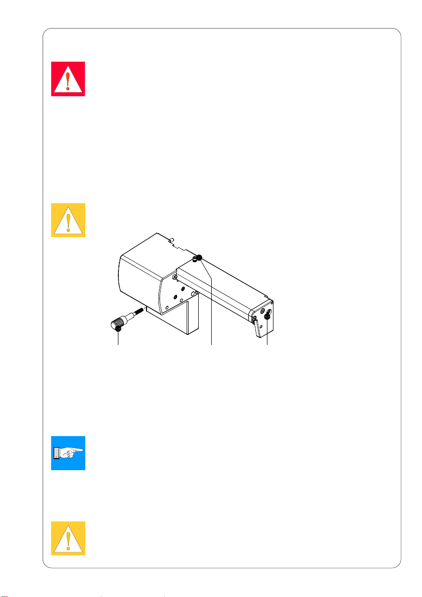
Media Loading
Load the transfer ribbon as described in the Printer’s Operators Manual.
Load the label media for cut mode similar to the way it would be loaded for
tear-off mode.
Place the media strip between the printhead and the drive roller, so that
the beginning of the strip reaches into the cutter.

8Cutter CU4
Operation
The printer is ready for operation when all connections have been made
and all materials are loaded correctly.
After loading the media it is necessary to locate top of form by pressing the
key. The media will be moved forward and then cut.
NOTICE!
To operate the cutter with continuous material configure the printer
under „Setup“ -> „Print parameters“ -> „Label sensor“, the setting
„Endless media“ has to be selected. Otherwise no cut is carried
out.
Locating the top of form is not necessary when the printhead was not
opened between print jobs. Even if the printer was powered off between
print jobs.
NOTICE!
To operate the cutter the cut mode must be activated in the
software!
For direct programming use the C-command (see Programming
Manual)!
Once the cutter is mounted on the printer and is ready for operation, the
printer can be used in cut mode.
All labels in a print job will be printed without stopping and be cut as
chosen in the software: after each label, after a specific quantity of labels,
or at the end of a print job.

9Cutter CU4
Cleaning
WARNING!
Before starting any maintenance, turn the printer OFF and
disconnect the printer from the electrical outlet!
During operation particles of dust and paper can accumulate inside the
cutter. Remove these particles with a soft brush or a vacuum.
When cutting through the label material instead of the label gap remains of
adhesive may accumulate on the blades.
If operating in backfeed mode, such remains of adhesive may be
deposited on the drive roller as well.
Therefore both, the drive roller and the cutter blades, must be cleaned
often.
CAUTION!
Risk of injury! The cutter blades are sharp!
231
Fig. 5 Cleaning the cutter
1. Loosen the screw (1) and remove the cutter from the printer.
2. For cleaning the drive roller open the print head and remove the
media from the printer.
3. For cleaning the circular blade you can turn the axle (3) with a
screwdriver for slotted head screws ( slot width 7mm).
NOTICE!
With the screw (2) the rotation angle of the circular blade is limited
to 120°. If you could not remove all pollutions from the circular
blade you can loosen the screw (2) about 5 mm from the profile to
turn the axle (3) 360°.
4. Remove all deposits both at the drive roller and the cutter blades with
isopropyl alcohol and a soft cloth.
CAUTION!
When you have loosen the screw (2) the circular blade has to be
repositioned after cleaning as described in chapter „Adjusting the
Circular Blade and the Clock Wheel“.

10 Cutter CU4
Changing the Blades
1. Turn the printer off and demount the cutter from the printer.
2. Turn the axle (3) of the circular blade (2) with a screwdriver for
slotted head screws (slot width 7mm) so that the inscription (1) of the
blade points downward.
In this position the set screw (4) on the „gear-wheel circular blade“
can be achieved from the rear of the cutter.
Loosen this set screw (4) a few turns.
Fig. 6 Loosen the screws
13
3. Hang out the spring (13) on the bearing plate (15) and the linear
blade (11).
NOTICE!
Attend on the washers (A, B, C) for the blades (2,11) when you
demount the bearing plate. The washers could get lost because of
theire smallness.
CAUTION!
Always keep the linear knife with one hand (11) in its position and
push its axle slightly to the mounting plate (9) of the cutter, because
the spring (6) is tense.
4. Unscrew the screws (8) and remove the bearing plate (15) sideways.
5. Take the circular blade (2) out of its bearing (5).
Now you can slacken the spring (6) of the linear blade.
If you don’t want to change the linear blade you can skip to #9.
6. Take the spring (6) and the linear blade (11) from the mounting plate
(9).
7. Insert the axle of the (new) linear blade withe the washer (B) in the
bearing (10) of the mounting plate. (The inscription of the linear blade
has to point downwards.)
8. Hang the spring (6) without tense on the pins of the mounting plate
(9) and the linear blade (11).
42

11Cutter CU4
9. Turn the linear blade (11) backwards. The spring (6) gets tense.
Insert the Axle of the (new) circular blade (2) with the washer (A) in
the bearing (5) of the mounting plate.
10. Place the washer (C) on the axle of the linear blade.
11. Hang the spring (13) without tense on the pins of the linear blade
(12) and the bearing plate (14).
12. Positioning the bearing plate (14) on the axles (2, 11). The spring
(13) gets tense.
NOTICE!
Attend on an accurate position of the bearing plate (15) to the
profile (7) of the cutter. A bad positioning could cause undefined
cutting edges.
13. Tighten the bearing plate (15) with the screws (8) at the profile (7).
Keep the bearing plate in position and push it slightly to the profile
(7) during tightening.
14. Tighten the screw set (4) of the „gear-wheel circular blade“ at the rear
of the printer.
CAUTION!
Before mounting the cutter the circular blade has to be repositioned
as described in chapter „Adjusting the Circular Blade and the Clock
Wheel“.
Fig. 7 Changing the circular and the linear blade
C
56 7 28
910 11 12 131415
A
B
2
11
Fig. 8 Washers for axles of the circular and the linear blade

12 Cutter CU4
Adjusting the Circular Blade and the Clock Wheel
To operate the cutter correctly after cleaning or after changing the blades
you have to adjust the axles of the circular blade (1) and the clockwheel (2)
to another.
A B 1 2 BA
Fig. 9 Position of the axles of the circular blade
and the clock wheel
1. Turn the printer off and remove the cutter.
2. Unscrew the cover (4) by loosening the screws (3), (5) and (9, at the
rear).
3. Loosen the screw (8) about 5 mm from the profile of the cutter.
4. Turn the axle (7) of the circular blade with a screwdriver (slot width
7mm) so that the inscription (4) of the blade points downward.
On the axles of the circular blade (1) and the clockwheel (2) you can
find a planar area (A, B).
Now or after one or two more full turns of the circular blade the areas
(A, B) both are pointing to the rear of the cutter and the axles are
adjusted.
6. Tighten the screw (8) for fixing the circular blade.
CAUTION!
If you tight screw (8) too strong, you could damage the screw
thread.
Fig. 10 Adjusting the circular blade to the clock wheel
8345617
9
9

13Cutter CU4
EU - Conformity Declaration
We declare herewith that as a result of the manner in which the machine designated below
was designed, the type of construction and the machines which, as a result have been
brought on to the general market comply with the relevant fundamental regulations of the EU
Rules for Safety and Health. In the event of any alteration which has not been approved by
us being made to any machine as designated below, this statement shall thereby be made
invalid.
Description: Type:
Cutter CU 4
Applied EU Regulations and Norms:
- EC Machinery Regulations 98/37/EU
-Machine Safety EN ISO 12100
- EC Low Voltage Regulations 73/23/EEC
- Data and Office Machine Safety EN 60950-1:2001
- EC Electromagnetic Compatibility
Regulations 89/336/EEC
- Threshold values for the Interference EN 55022:1998+A1:2000+A2:2003
of Data Machines -classA
Gesellschaft für Computer-
undAutomations-
Bausteine mbH
Wilhelm-Schickard-Str.14
D-76131Karlsruhe
Signed for, and on behalf of, the Manufacturer :
cab Produkttechnik Sömmerda
Gesellschaft für Computer-
und Automationsbausteine mbH
99610 Sömmerda
Sömmerda, 10.04.06
Erwin Fascher
Managing Director
This declaration is valid only when the cutter is used together with printers of the
BP-PR PLUS series, Manufacturer: cab - Karlsruhe.

W.H. Brady
Lindestraat 21
Industriepark C3
9240 Zele Belgium
Tel.: +32 52 457 811
e-mail: support@brady.be
All specifications about delivery, design, performance and weight are given to the best of our current knowledge and are subject
to change without prior notice.
Identification Solutions Division
6555 W. Good Hope Road
PO Box 2131
Milwaukee, WI 53201 U.S.A.
Phone: 1-800-537-8791
Fax: 1-800-292-2289
Table of contents
Other Brady Printer Accessories manuals