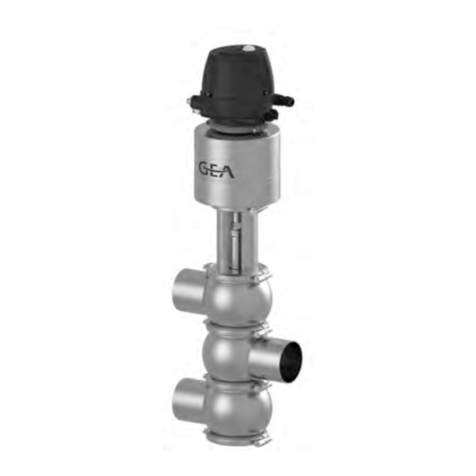
GEA AVR Series User manual

1 / 8
GEA AWP GmbH
Armaturenstr. 2
17291 Prenzlau, Germany
Tel.: +49 3984 8559-0 Fax: +49 3984 8559-18
AVR_96300 10.03.2014
APS 06.30
–
1
0
.
3
Shut off Valves
with rising stem
AVR
– types example:
with PTFE-ring seal on the stem
963 00, 964 00
– cover flanged
963 10, 964 10
– cover flanged and extension
Contents Page
1. Survey of Types 2
2. Technical Characteristics 2
3. Safety Instructions 3
4. Application 3
5. Functional Description 3
6. Installation 4
7. Maintenance 4
8. Transport, Storage 6
9. Warranty 6
10. Spare parts 6
11. Specification 8
12. Information on risks 8
Absperrventile
mit steigender Spindel
AVR
– Typenvertreter:
mit elastischer PTFE-Ring Abdichtung an der Spindel
963 00, 964 00
– Deckel geflanscht
963 10, 964 10
– Deckel geflanscht und verlängert
Inhaltsverzeichnis Seite
1. Übersicht der Bauarten 2
2. Technische Kennwerte 2
3. Sicherheitshinweise 3
4. Anwendung 3
5. Funktionsbeschreibung 3
6. Einbau 4
7. Wartung 4
8. Transport und Lagerung 6
9. Garantie 6
10. Ersatzteile 6
11. Kennzeichnung 8
12. Hinweis auf Restgefahren 8
Betriebsvorschrift
Armaturen für die Kältetechnik
Operating Instructions
Valves for refrigeration

2 / 8
GEA AWP GmbH
Armaturenstr. 2
17291 Prenzlau, Germany
Tel.: +49 3984 8559-0 Fax: +49 3984 8559-18
AVR_96300 10.03.2014
APS 06.30
–
1
0
.
3
1. Übersicht der Bauarten 1. Survey of types
Typ / type DN6 - 20
963 00, 964 00
963 10, 964 10
2. Technische Kennwerte 2. Technical characteristics
Gehäusewerkstoff body material selection of material according to
Auswahl nach DIN EN12284, AD-2000 Reihe W German DIN EN12284, AD-2000 Reihe W,
St: P235GH, S355J2 St: P235GH, S355J2
TT: P215NL, P255QL, P355NL1 TT: P215NL, P255QL, P355NL1
NIRO: X5CrNi18-10 NIRO: X5CrNi18-10
oder gleichwertige or any equivalent
bei Verwendung von Schrauben der by using screws 8.8
Festigkeitsklasse 8.8
PN TB (MWT) [C°] -60* -40* -25* -10 +50 +150
25 PS (MWP) [bar] 5 12,5 18,7 25 25 25
40 8 20 30 40 40 40
63 12,6 31,5 47,2 63 63 63
bei Verwendung von Schrauben der by using screws A2-70
Festigkeitsklasse A2-70
PN TB (MWT) [C°] -60* -60** -10 +50 +150
25 PS (MWP) [bar] 18,7 25 25 25 25
40 30 40 40 40 40
63 47,2 63 63 63 63
** Beanspruchungsfall I (TT, Niro) ** kind of straining I (TT, Niro)
* Beanspruchungsfall II ( nach AD2000-W10, * kind of straining II ( after AD2000-W10,
EN 12284) (ST) EN 12284) (ST)
Schraubbuchse
screw bushing
Flachdichtung SB
flat sealing
-
ring
Abstreifring
scraper
Flachdichtring R
flat sealing ring R PTFE-Ring
PTFE
-
rings seal
Kappe
cap
Handrad
handwheel
Flachdichtring K
flat sealing-ring K
Spindel
stem cmpl
B A
O-Ringe
o-rings
Flachdichtring S
flat sealing-ring S

3 / 8
GEA AWP GmbH
Armaturenstr. 2
17291 Prenzlau, Germany
Tel.: +49 3984 8559-0 Fax: +49 3984 8559-18
AVR_96300 10.03.2014
APS 06.30
–
1
0
.
3
working media
cold brine basing on glycol refrigerant EN 378 p. 1 and
mixtures with refrigerator oil, neutral, gaseous and liquid
media, cold brine basing on glycol
flow factor (m
3
/h)
mounting position in any desired position, the flow direction
should be observed
leakage outward,
seat <5g refrigerant per year
3. Safety instructions
! Valves that have been damaged during transport or
storage must not be installed.
! Valves:
•no axial forces, bending or torsion moments
should act upon the valves.
•must not be used as fixing points for pipes
! In the case of gase welding or brazing, the flame may not
reach the valve.
! Any kind of soiling has to be kept away from the inside of
the valve.
! It is not allowed to open or close the valves by means of a
hand wheel wrench or any other devices for extending the
lever arm, as this may damage the seat sealing.
! The valves may not be disassembled or detached before
the pipe has been depressurized, sucked off and
adequately ventilated.
4. Application
AWP- Shut off valves are suitable for being employed in
the refrigerant cycles for industrial refrigerating plants.
5. Functional description
AWP - Shut off valves are actuated by a hand wheel. They
are shut off clockwise in viewing direction towards the
operating element and are opened counterclockwise. The
valves are shut-off devices and may only be operated in
"shut-off" or "open" position. When opening the valve, the
stem has to be moved to the limit stop into the uppermost
position (completely open). The valves are equipped with a
back sealing (flat sealing ring R).
When the valve is completely open, it is possible to re-
place the sealing elements (O-rings, A, B, PTFE-ring) at
the stem safety by unscrewing bushing.
In case the flow medium reaches extreme temperatures,
the valve must be handled with protective gloves, -danger
of burning-.
Actuating the valve against a liquid in a closed section
should be avoid, as the motion of the stem sauses a chan-
ge in volume within the valve body.
Betriebsmedien
Kältemittel EN 378 Teil 1, z.B.NH3, R22, R134a, Blends
und Gemische mit Kältemaschinenöl, neutrale, gasförmige
und flüssige Medien Kühlsole auf Glycol-Basis,
Durchflusswert KVS
Einbauanlage beliebig, Durchflußrichtung sollte eingehalten
werden
Leckage nach außen,
Sitz <5g Kältemittel im Jahr
3. Sicherheitshinweise
! Ventile mit Transport- oder Lagerschäden dürfen nicht
eingebaut werden.
! Ventile:
•müssen frei von Achskräften, Biege- und
Torsionsmomenten sein
•dürfen nicht als Fixpunkte von Rohrleitungen
dienen.
! Bei Autogenschweißung oder Hartlötung darf die Flamme
das Ventil nicht berühren.
! Verunreinigungen jeglicher Art müssen vom Innenraum
der Ventile ferngehalten werden.
! Schließen oder Öffnen der Ventile mit einer Handradgabel
oder sonstiger hebelarmverlängernder Gegenstände ist
unzulässig, da dies zur Beschädigung der Sitzdichtung
führen kann.
! Demontage bzw. Ausbau der Ventile nur bei druckloser,
abgesaugter und ausreichendbelüfteter Rohrleitung.
4. Anwendung
AWP-Absperrventile sind geeignet für den Einsatz in
Kältemittelkreisläufen für Industrie-Kälteanlagen.
5. Funktionsbeschreibung
AWP –Absperrventile sind durch ein Handrad zu betä-
tigen. Die Ventile werden mit Blickrichtung auf das Handrad
rechtsdrehend geschlossen und linksdrehend geöffnet. Die
Ventile sind Absperrarmaturen und dürfen nur in "Auf"-oder
"Zu"-Stellung gefahren werden. Beim Öffnen des Ventils ist
die Spindel bis zum Anschlag in die oberste Stellung zu
fahren (voll geöffnet). Die Ventile sind mit einer
Rückdichtung ausgerüstet (Flachdichtring R).
Bei voll geöffnetem Ventil ist der gefahrlose Austausch
der Dichtelemente (O-Ringe A, B, PTFE-Ringe) an der
Spindel, durch Herausschrauben der Schraubbuchse
möglich.
Bei extremen Temperaturen ist das Ventil mit Schutz-
handschuhen zu bedienen.
Die Betätigung des Absperrventils gegen eine einge-
schlossene Flüssigkeit ist zu vermeiden, da es durch die
Bewegung der Spindel zur Volumenänderung kommt.
Zulässiger Umgebungstemperaturbereich (C°) permissible ambient temperature range (C°)
-50 bis +50 -50 to +50
DN 6 8 10 15 20
963 00 1,50 2,15 2,60
2,90 5,20
964 00 2,10
2,80 3,85 4,90 8,75
4 / 8
GEA AWP GmbH
Armaturenstr. 2
17291 Prenzlau, Germany
Tel.: +49 3984 8559-0 Fax: +49 3984 8559-18
AVR_96300 10.03.2014
APS 06.30
–
1
0
.
3
This, in turn, causes an inadmissible increase of pressure
in the closed pipe section. Valves in pipes for liquids have
to be shut off in direction towards a vessel containing gas.
! DN 300 to 400 with balancing valve disk!
6. Installation
Before installing the valves, the pipelines and the compo-
nents have to be cleaned.
-please notice-
The deviation from the parallelism or squareness of the
welding ends or, as the case may be, the sealing surfaces
of the flanges must not exceed 1°.
The connecting flanges have to be coaxial. Valves that
have been damaged during transport or storage must not
be installed.
After the protective caps have been removed, the valves
can be welded on, or installed in any position. The flow
direction (see arrow on specification label) should be
observed.
With modern welding processes (such as TIG, CO2-
shielded metal-arc), the valves are not disassembled for
welding.
The fastening bolts and nuts have to be tightened crosswise
andevenly.
After the installation has been performed, check whether the
hand wheelrunssmoothlywithinitsentireliftrange.
The thread of the cover for unscrewing the cap must not be
painted and has to be greased (e.g. with RENAX UNITEMP
2). -pleasenotice-
For disassembling the valve sufficient space has to be
providedonthesideofthecover.
7. Maintenance
AWP-shut off valves are maintenance-free. In case any
defects in the functional performance of the valves occur,
they can be repaired. During the term of warranty, repairs
may only be carried out by the AWP or -with his consent by
specially-trained maintenance personal working for the
plant operator.
!
Safety instructions please notice
•Replacing the stem sealing
(During operation of the system)
1. Screw off the cap
2. Move the stem by means of the uppermost
position.
Dies bedingt eine unzulässige Druckzunahme im
abgeschlossenen Rohrabschnitt. Das Schließen der
Absperrventile in Flüssigkeitsleitungen hat in Reihenfolge
zu einem Behälter mit Gasvolumen zu erfolgen.
! DN 300 bis 400 mit Ventiltellerentlastung!
6. Einbau
Vor Einbau der Ventile sind Rohrleitungen und Anlagenteile
zu säubern. -bitte beachten-
Die Abweichung von der Parallelität bzw. Rechtwinkligkeit
der Anschweißenden bzw. Flanschdichtflächen darf 1° nicht
überschreiten.
Anschlußflansche müssen achsengleich sein. Ventile mit
Transport-und Lagerschäden dürfen nicht eingebaut
werden.
Nach dem Entfernen der Rohrstopfen können die Ventile in
beliebiger Lage eingeschweißt bzw. montiert werden. Die
Durchflußrichtung (siehe Pfeil auf Kennzeichenschild)
sollte eingehalten werden. Eine entgegengesetzte
Durchflußrichtung ist zulässig, die Leistungsangaben gelten
dannnicht.
Bei Anwendung moderner Schweißverfahren (z.B.
WIG, CO2) werden die Ventile zum Einschweißen nicht
demontiert. Das Handrad ist in Mittelstellung zu bringen.
Die Befestigungsschrauben und Muttern sind über
Kreuzundgleichmäßiganzuziehen.
Nach dem Einbau ist die Leichtgängigkeit des Handradesim
kompletten Hubbereich zu überprüfen. Das Deckelgewinde
zumAufschrauben der Kappe hat farbfrei zu bleiben und ist
zu fetten (z.B. mit RENAX UNITEMP2).
-bittebeachten-
Zur Demontage des Einsatzes ist genügend Platz auf
derDeckelseitevorzusehen.
7. Wartung
AWP-Absperrventile arbeiten wartungsfrei. Treten Mängel
im Funktionsverhalten auf, ist eine Reparatur möglich.
Während der Garantiezeit dürfen Reparaturen nur durch
AWP bzw. mit dessen Einverständnis durchgeschultes
Instandhaltungspersonal des Betreibers der Anlage
vorgenommen werden.
!
Sicherheitshinweise beachten
•Auswechseln der Spindelabdichtung
(bei Betrieb der Anlage)
1. Kappe abschrauben
2. Spindel mittels Handrad bis zum Anschlag in die
oberste Stellung fahren.
DN
6
-
15
20
mm
25 30
DN
6
-
20
SW
19

5 / 8
GEA AWP GmbH
Armaturenstr. 2
17291 Prenzlau, Germany
Tel.: +49 3984 8559-0 Fax: +49 3984 8559-18
AVR_96300 10.03.2014
APS 06.30
–
1
0
.
3
3. Screw off the screw bushing counter-clockwise.
!
The screw bushing should be kept loosely in
the cover until the pressure has equalized totally.
Only then should it be unscrewed completely.
4. Remove the o-ring seals A, B, PTFE-ring and the
scraper and replace them by new ones. Remove
flat sealing ring SB from the seal housing in the
cover.
5. Clean the stem.
6. Insert a new flat sealing-ring SB into the cover.
Lubricate the screw bushing with low-temperature
grease (RENAXUNITEMP 2) or any other appro-
priate lubricant and fasten it finger tight.
7. For leakage test move the stem into central
position and coat the cover area with a foaming
agent.
•Replacing the flat sealing ring S and R, or
stem cmpl.
1. Open the valve up to the limit stop. Loosen the
cover screws German Standard ISO 4762.
!
The cover screws should be kept loosely in the body until
the pressure has equalized totally. Only then should it be
unscrewed completely.
2. Unscrew cover screws and draw out the cover
including internal parts by means of the
handwheel.
3. Screw the handwheel from the stem and turn the
stem out of the cover.
4. Remove the flat sealing ring R and replace it.
5. Remove the seat sealing and replace it.
Before mounting, clean all component parts of the valves;
grease stem and the cover.
Afterwards another flat sealing ring is inserted, the cover is
put back in its place and is tightened by means of the
screws evenly and crosswise.
3. Schraubbuchse links herum herausschrauben.
!
Auf eventuell austretendes restliches Kältemittel
achten. Bis zum völligen Druckausgleich
Schraubbuchse lose im Deckel belassen.
Erst danach völlig herausschrauben
4. O-Ringe A, B, PTFE-Ring und Abstreifring
entfernen und durch neue ersetzen.
Flachdichtring SB aus dem Einbauraum im
Deckel entfernen.
5. Spindel säubern.
6. Neuen Flachdichtring SB in Deckel einlegen.
Schraubbuchse mit Kältefett (RENAXUNITEMP2)
bzw. gleichwertiges einfetten und handfest
anziehen.
7. Zur Dichtheitskontrolle ist die Spindel in Mittel-
stellung zubringen und der Deckelbereich mit
Schaummitteln einzupinseln.
•Auswechseln Flachdichtring S und R bzw.
Spindel kpl.
1. Ventil bis Anschlag öffnen. Deckelschrauben
ISO 4762 lösen.
!
Auf eventuell austretendes restliches Kältemittel achten.
Bis zum völligen Druckausgleich Deckelschrauben lose im
Gehäuse belassen. Erst danach völlig herausschrauben.
Schrauben
screws
2. Deckelschrauben herausschrauben und Deckel
einschließlich Innenteile am Handrad
herausziehen.
3. Handrad von der Spindel abschrauben und die
Spindel aus dem Deckel herausdrehen.
4. Flachdichtring R herausnehmen und ersetzen.
5. Sitzdichtung entfernen und durch neue ersetzen.
Vor der Montage sind alle Einzelteile der Ventile zu
reinigen, die Spindel und der Deckel einzufetten.
Anschließend wird noch ein Flachdichtring K eingelegt, der
Deckel aufgesetzt und mit den Schrauben gleichmäßig und
über Kreuz angezogen.
DN
6
-
15
20
SW
19 17
DN
6
-
15
20
M
6 8
SW
5 6
DN
6
-
15
20
M6x18 8x20
ISO 4762 (8.8)
SW 5 6
Anziehdrehmoment / tightening moment [Nm]
10 25

6 / 8
GEA AWP GmbH
Armaturenstr. 2
17291 Prenzlau, Germany
Tel.: +49 3984 8559-0 Fax: +49 3984 8559-18
AVR_96300 10.03.2014
APS 06.30
–
1
0
.
3
8.
Transport und Lagerung
AWP-Absperrventile werden stoßgeschützt, mit Folie
abgedeckt transportiert. Die Lagerung hat in trockenen
Räumen zu erfolgen. Es ist auf den unversehrten
Verschluss der Anschlussstutzen zu achten.
Verschmutzungen jeglicher Art müssen vom Innenraum
ferngehalten werden.
Die außenliegenden Flächen der Armaturen sind mit einem
Korrosionsschutzanstrich für trockene Lagerung bei
Raumtemperatur versehen, der mindestens 1 Jahr wirksam
ist.
Der Korrosionsschutzanstrich BISPHENOL-A-Epoxidharz
ist ein guter Haftvermittler für Deckanstrichstoffe auf 1- und
2- Komponenten-Basis.
9. Garantie
Die Garantieleistung für Erzeugnisse ist entsprechend den
vertraglichen Bestimmungen im Liefervertrag festgelegt.
10. Ersatzteile
Ersatzteile entsprechend Bild Seite 2:
Ersatzteilbestellung: (muss enthalten)
•
Anzahl
•
Bezeichnung entsprechen Bilder für Typ
•
Bestell-Nummer
•
Nennweite der Armatur
•
Baujahr der Armatur
Bestellbeispiel:
3 Stück, Spindel kpl. AVR, 963 00
963 00E10.5060001,
DN15, 08/2010
8.
Transport, Storage
During transport, AWP shut off valves are protected
against shocks and covered with plastic sheeting. They
should be stored in dry rooms. Care has to be taken that
the plugs of the connecting pieces are not damaged. Any
kind of soiling has to be kept away from the inside of the
fitting.
The external surfaces of the valves are provided with a lay-
er of anticorrosive paint for dry storing at room temperature,
which remains effective for at least 1 year.
The anticorrosive paint which BISPHENOL-A-Epoxidharz
is a good bonding agent for one or two-pot finishing coating
paints.
9. Warranty
The warranty services for our products have been defined
incompliance with the regulations stipulated the contract of
delivery.
10. Spare parts
Spare parts according to the illustration sheet page 2:
Ordering Spare parts: (an order must contain):
•
quantity
•
designation according to illustration sheet page 2
•
stock number
•
nominal diameter of the fitting
•
year of construction of the fitting
Example for ordering
3 pieces, stem cmpl. AVR, 963 00
963 00E10.5060001,
DN15, 08/2010

7 / 8
GEA AWP GmbH
Armaturenstr. 2
17291 Prenzlau, Germany
Tel.: +49 3984 8559-0 Fax: +49 3984 8559-18
AVR_96300 10.03.2014
APS 06.30
–
1
0
.
3
O
-
Ring A / o
-
ring
seal A
CR75
O
-
Ring B / o
-
ring seal B
CR75
DN Bestellnummer Abmessung DN Bestellnummer Abmessung
stock number dimension stock number dimension
6-15 73 75 52 ᴓ8 x 3 6-15 73 75 12 ᴓ14 x 1,5
20 73 74 98 ᴓ10 x 3 20 73 77 14 ᴓ14 x 2
PTFE
-
Ring / PTFE
-
ring seal
Abstreifri
ng / scraper
NBR85
DN Bestellnummer Abmessung DN Bestellnummer Abmessung
stock number dimension stock number dimension
6-15 72 84 05 ᴓ8 x 13 / 3,9 6-15 73 98 36 ᴓ8 x 14 x 5
20 73 84 16 ᴓ10 x 14,5 / 3,6 20 73 98 35 ᴓ10 x 16 x 5
Handrad / handwheel
Kappe / cap
DN Bestellnummer Abmessung DN Bestellnummer Abmessung
stock number dimension stock number dimension
6-15 363 02.10.5 280 00 3 ᴓ60 x 6/9 6-15 96300E10.3 180 01 3 M27 x 2
20 363 02.10.5 280 00 3 ᴓ60 x 6/9 20 96300E10.3 180 01 3 M27 x 2
Flachdichtring SB / flat sealing ring SB
AFM30
Flachdichtring K / flat sealing ring K
AFM30
DN Bestellnummer Abmessung DN Bestellnummer Abmessung
stock number dimension stock number dimension
6-15 363 02. 10.4 143 00 3 ᴓ8,1 x 16,3 x 2,0 6-15 57 36 61 21 x 26 x 1,5
20 963 00E11.4 143 00 3 ᴓ17,8 x 12,1 x 2,0 20 73 74 92 26 x 31 x 2,0
Flachdichtring
R
/ flat sealing ring
R
PTFE
Flachdichtring
S
/ flat sealing ring
S
PTFE
DN Bestellnummer Abmessung DN Bestellnummer Abmessung
stock number dimension stock number dimension
6-15 363 02. 10.2 145 00 3 ᴓ10 x 16 x 2,0 6-15 963 00E10.2 144 00 3 9 x 19 x 3,0
20 963 00E11.2 145 00 3 ᴓ12 x 18 x 2,0 20 963 00E11.2 144 00 3 12 x 23 x 3,0
Schraubbuchse kpl. / screw bushing cmpl.
Spindel kpl. / stem cmpl.
DN Bestellnummer / stock number Typ / type: 963 00, 964 00 Typ / type: 963 10, 964 10
6-15 963 00E10.8 142 001 963 00E10.5 060 00 1 963 10E10.5 060 00 1
20 963 00E11.8 142 001 963 00E11.5 060 00 1 963 10E11.5 060 00 1

8 / 8
GEA AWP GmbH
Armaturenstr. 2
17291 Prenzlau, Germany
Tel.: +49 3984 8559-0 Fax: +49 3984 8559-18
AVR_96300 10.03.2014
APS 06.30
–
1
0
.
3
11.
Kennzeichnung
Die Kennzeichnung der AWP-Absperrventile erfolgt
entsprechend EN12284 auf dem Ventilgehäuse.
•DN -Nennweite (ab DN 20)
•PS -zulässiger Druck (ab DN 20)
•Werkstoffkennzahl
•Kennung und Chargen-Nr. der Schmiede
•Typ-Nr. (963 bzw. 964)
•Ventil - Typ (AVR)
•Hersteller (AWP)
•
Durchflußpfeil
12. Hinweis auf Restgefahren entsprechend
der Druckgeräterichtlinie (97/23/EG)
Vom Hersteller nicht zu vermeidende Restgefahren
bestehen durch:
- Unbefugtes Lösen des Deckels während des
Betriebes bzw. Lösen der Schraubbuchse ohne
Aktivierung der Rückdichtung
- Unsachgemäße Montage von
Flanschverbindungen (Eingangs- und
Ausgangsflansch, Deckel)
- Verschmutzungen im Betriebsmedium bzw.
Unsachgemäßer Umgang mit Einbauteilen
können zu Beschädigungen an der Sitzdichtung
führen
- Nichtbeachtung der Einsatzgrenzen und
Herstellervorschriften entsprechend dieser
Betriebsvorschrift
11.
Specification
The specification of the AWP-shut off valves complies with
German Standard EN12284 on the casing.
•dimension (from DN 20)
•permissible pressure (from DN 20)
•material characteristic
•identification and charge - no forge
•type - no. (963 or 964)
•valve type (AVR)
•manufacturer (AWP)
•
flow direction
12. Information on risks in conformance to
pressure appliance directive
Remaining risks which cannot be avoided by the
manufacturer arise because of:
- Unauthorized loosening of the cover during
operation or removing of the screw bushing
without activation of the back sealing
- Incorrect assembly oft he flange connections
(inlet and outlet flange, lid)
- Dirt in the service medium or inappropriate
handling of the internal fittings may cause
damage to the seat seal
- Ignore of the operating range and manufacturer
rules acc. to this operating instruction
This manual suits for next models
4
Table of contents
Other GEA Control Unit manuals

GEA
GEA HRAB User manual

GEA
GEA VARIVENT Vacuum Valve V User manual

GEA
GEA VARIVENT D Series User manual

GEA
GEA VARIVENT 24/7 PMO User manual

GEA
GEA Aseptomag GD User manual

GEA
GEA Aseptomag AMV User manual

GEA
GEA VARIVENT T R User manual

GEA
GEA VARIVENT DN 25 User manual

GEA
GEA ECOVENT N/W User manual

GEA
GEA VARIVENT A Quick guide
Popular Control Unit manuals by other brands

Samsung
Samsung MCU-R4NEK0N installation manual

GE
GE Masoneilan VariPak 28001 instruction manual

Sun Hydraulics
Sun Hydraulics XMD-01 user manual

ABRACON CORPORATION
ABRACON CORPORATION ABBTM-NVC-MDCS56 manual

APV
APV FS9000 Series Installation, operation & maintenance manual

White Rodgers
White Rodgers 36J27-554 installation instructions