Branick Industries, Inc. 5700E Use and care manual
REV031318 P/N: 81-0289
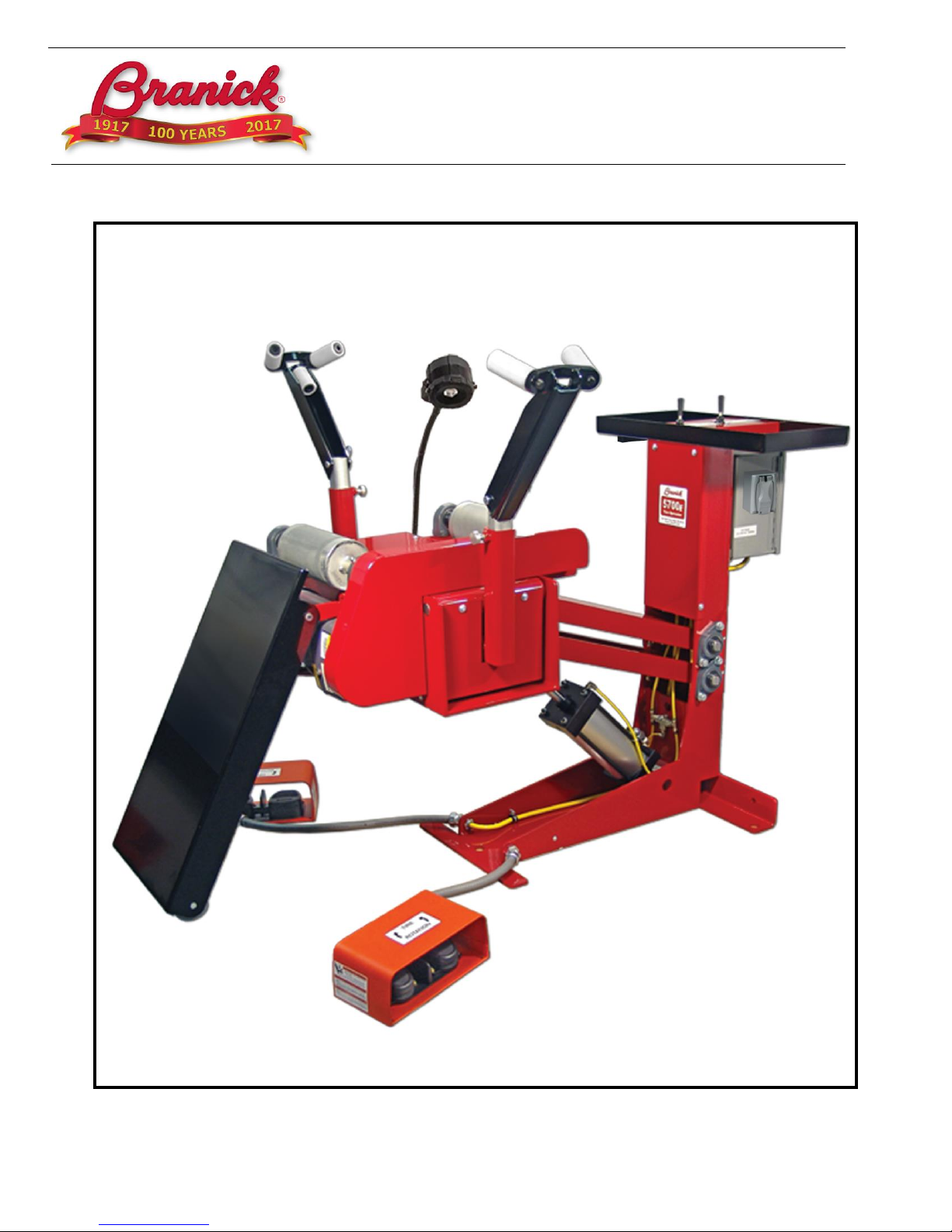
MODEL 5700E
Adjustable Height
Tire Spreader
Installation, Operation
& Repair Parts
Information
Branick Industries, Inc. •4245 Main Avenue •Fargo, North Dakota 58103

1
TABLE OF CONTENTS _________________________________________________________________
SAFETY INSTRUCTIONS 1
DEFINITIONS 1
SPECIFICATIONS 2
INSTALLATION INSTRUCTIONS 2
OPERATING INSTRUCTIONS 3
ADDITIONAL FEATURES 3
MAINTENANCE 3
REPAIR PARTS 4
WARRANTY 11
SAFETY INSTRUCTIONS _______________________________________________________________
▪NEVER allow unauthorized personnel to operate this product.
▪NEVER use this product for anything other than its intended use.
▪THOROUGHLY train new employees in the proper use and care of this product.
▪PROHIBIT unauthorized personnel from being in shop area while this product is in use.
DEFINITIONS __________________________________________________________________________
▪CAUTION: Indicates a potentially hazardous situation, which if not avoided, may result in damage to property or
minor personal injury.
▪HAZARD: A source of potential injury to a person.
▪MAINTENANCE: Those actions that preserve the correct and proper conditions under which the machine shall be
used. This may include adjustment, replacement of wear items, lubrication and cleaning, but not modifications or
repair of damage.
▪MAY: This word is understood to be permissive.
▪MUST: This word is understood to be mandatory.
▪OPERATION: The correct and proper use of the machine as described in this manual.
▪SAFETY ALERT SYMBOL: A symbol that indicates a potential personal safety hazard. It is composed of an
equilateral triangle surrounding an exclamation point.
▪SHALL: This word is understood to be mandatory.
▪SHOULD: This word is understood to be advisory.
▪WARNING: Indicates a potentially hazardous situation, which if not avoided, may result in death or serious
personal injury.
2
SPECIFICATIONS______________________________________________________________________
Max Compressed Air Supply: 150 psi (10.3 bar)
Dimensional data: 51 x 38 x 68 in (130 x 97 x 173 cm)
Weight: 660 lbs (300 kgs)
INSTALLATION________________________________________________________________________
1) Unpack and remove unit from shipping pallet.
2) Position the Model 5700 on a solid level floor leaving adequate clearance for operator. Anchor unit to floor using
appropriate anchor bolts (not provided) through the three bolt holes on the base of the unit.
3) Install a 1/4" NPT quick coupler nipple (not provided) into the air inlet port of regulator located at the base of the
control column.
4) Connect the shop air line to the quick coupler nipple.
5) Connect the unit and the light to any convenient 110/120V power source.
CAUTION
Before using this product, read and fully understand the operating
instructions and all decals on the product. This is necessary to prevent
injury to the operator and damage to the product.
This product is intended to be used to spread and rotate tire casings for
inspection and/or repair only.
Keep fingers and hands clear of all hooks and mechanisms during
operation.
Do not use this product if it is visibly worn, distorted or damaged.
Always wear appropriate eye protection.
WARNING
Keep feet clear of the tire lift when raising and lowering tire.
All personnel must be clear of the spread arms during operation.

3
OPERATING INSTRUCTIONS_____________________________________________________________
1) Turn the power switch to the ON position.
2) Lower the inspection platform completely using the hand control valve at the tool tray.
3) Pull the bead hooks up and away from the center of the machine.
4) Roll a tire up the ramp and center it on the rollers. Lower the bead hooks inside the tire making sure the bead rollers
are inside the tire bead. The vertical position of the bead hooks is adjustable using the quick pin release on the side
of the bead hook arm.
5) Steady the tire while raising the inspection platform to a comfortable working height.
6) Use the tire spread hand control valve at the tool tray to spread the tire as required. The light can be positioned to
view any portion of the tire.
NOTE: If the tire is lifted off the rollers when spread, release spread and move spread hooks to a lower position.
7) Rotate the tire using the foot controls. Release the foot pedal to stop rotation for inspection. Rotation speed can be
adjusted using the Speed Control dial. Repeat this operation until inspection is complete.
8) When inspection is complete, close the bead hooks fully and swing them up and out of the tire. Move the light fixture
out of the tire.
9) Lower the inspection platform completely and roll the tire off the rollers and down the ramp.
10) Turn the power switch to the OFF position.
ADDITIONAL FEATURES__________________________________________________________________
1) There are 4 air tool ports located below the tool tray. Attach a 1/4” NPT quick coupler to each port and attach air tools
as needed.
2) There are two electrical outlets located on the control column. The power switch must be in the ON position to supply
power to these outlets.
MAINTENANCE_________________________________________________________________________
MONTHLY –Inspect unit for air leaks and wear or damage on pins and rollers.
Lubricate all moving parts (bolts, hinges, rollers, etc.) with a lubricating oil.
YEARLY - Grease all bearings using grease zerks.
CAUTION
Before servicing machine disconnect air line from the unit and unplug
the power cord.
4
REPAIR PARTS ___________________________________________________________________________
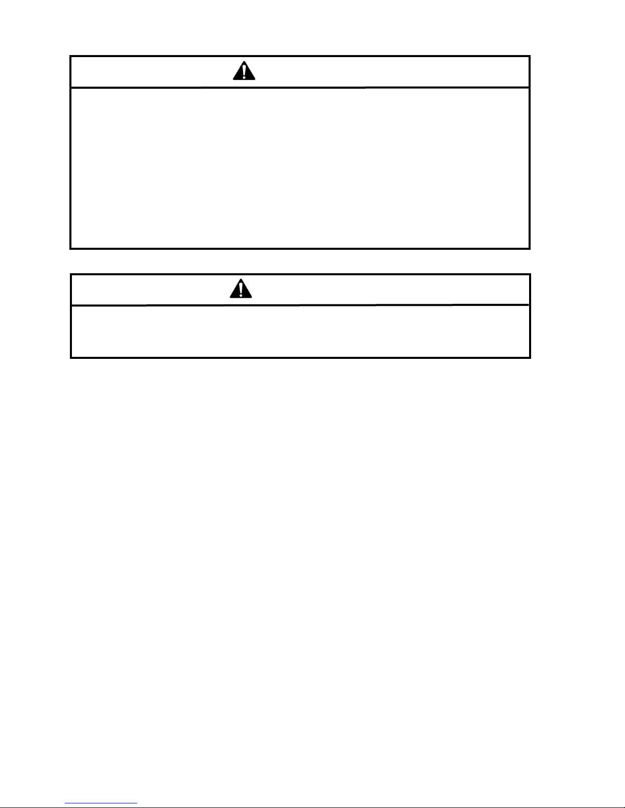
BASE ASSEMBLY
ITEM
PART NO.
DESCRIPTION
1
03-0641
UPPER LIFT ARM
2
20-0059
PILLOW BLOCK BEARING
3
20-0060
FLANGE BEARING
4
50-0065
3/8-16 X 3/4 SERRATED FLANGE SCREW
5
50-0125
1/4-20 X 5/8 BUTTON HEAD SCREW
6
50-0185
7/16-14 X 1-1/4 CARRIAGE BOLT
7
50-0186
M5 X 0.8 X 16 MACHINE SCREW
8
51-0062
7/16-14 SERRATED FLANGE LOCK NUT
9
53-0034
ONE PIECE CLAMP
10
71-0397
LIFT ARM
11
72-0537
TOOL TRAY
12
72-0538
CONTROL PANEL
13
72-0539
COLUMN PANEL
14
73-1160
LIFT ARM ROD - LONG
15
73-1161
LIFT ARM ROD - SHORT
16
74-0377
LIFT ARM SPACER
17
108-110
1/4 WASHER

5
CRADLE ASSEMBLY

6
CRADLE ASSEMBLY
ITEM
PART NO.
DESCRIPTION
1
01-0267
EQUALIZER LINKAGE
2
03-0638
CHAIN GUARD
3
03-0639
RAMP
4
03-0644
SPREAD ARM PIVOT - RIGHT
5
03-0645
SPREAD ARM PIVOT - LEFT
6
03-0646
SPREAD ARM
7
03-0647
KNURLED ROLLER - FRONT
8
03-0648
KNURLED ROLLER - REAR
9
40-0090
LED LIGHT FIXTURE
10
10-0032
BUMPER
11
11-0117
SPREAD ROLLER
12
11-0118
BEAD ROLLER
13
20-0059
PILLOW BLOCK BEARING
14
20-0061
FLANGE BUSHING
15
21-0018
1/4 X 1 KEY
16
21-0019
1/4 X 2 KEY
17
22-0018
25 TOOTH SPROCKET
18
22-0019
14 TOOTH SPROCKET
19
23-0007
#40 OFFSET LINK
20
028-161
#10-24 X 1 MACHINE SCREW
21
028-243
1/2 X 1-3/4 SHOULDER SCREW
22
50-0065
3/8-16 X 3/4 SERRATED FLANGE SCREW
23
50-0088
1/4-20 X 1-3/4 HEX HEAD SCREW
24
50-0094
3/4 X 3 SHOULDER SCREW
25
50-0125
1/4-20 X 5/8 BUTTON HEAD SCREW
26
50-0153
3/4 X 2 SHOULDER SCREW
27
50-0187
3/8 X 3/8 SHOULDER SCREW
28
50-0188
3/8 X 5/8 SHOULDER SCREW
29
51-0063
5/8-11 HEX JAM NUT
30
54-0058
RETRACTABLE PLUNGER
31
055-127
#10-24 HEX LOCK NUT
32
055-145
5/16-18 HEX LOCK NUT
33
055-154
3/8-16 HEX LOCK NUT
34
055-160
1/4-20 HEX LOCK NUT
35
062-045
#40 CONNECTING LINK
36
72-0548
CRADLE COVER
37
72-0549
SPREAD ARM GUARD
38
73-1164
SPREAD ARM PIVOT ROD
39
74-0381
ADJUSTMENT POST
40
90-0003
WHEEL
41
108-015
3/8 WASHER
42
108-110
1/4 WASHER
43
108-155
1/4 FENDER WASHER
44
B20-001
#40 ROLLER CHAIN
7
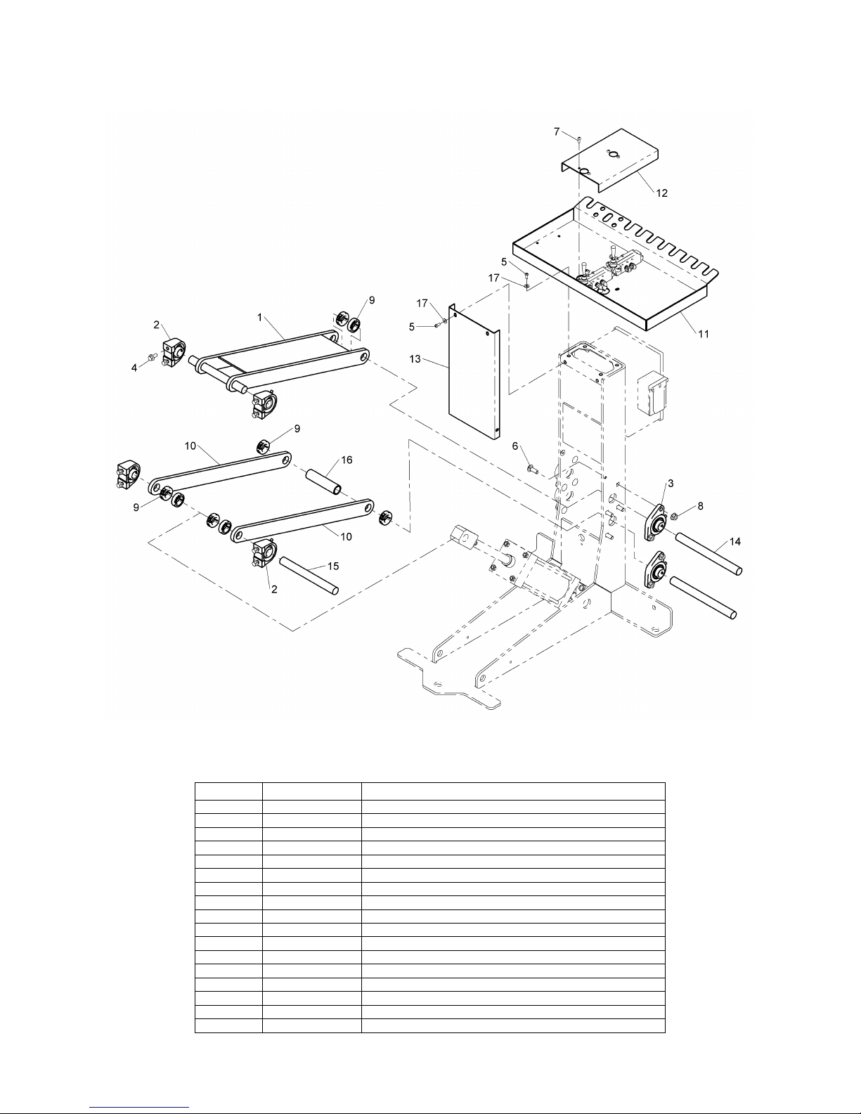
ELECTRICAL

8
ELECTRICAL
ITEM
PART NO.
DESCRIPTION
1
40-0090
LED LIGHT FIXTURE
2
24-0016
1/2 HP GEARMOTOR
3
028-059
5/16-18 X 1-1/4 HEX HEAD SCREW
4
028-155
#10-24 X 5/8 MACHINE SCREW
5
40-0083
POWER CORD CABLE GRIP
6
40-0099
VARIABLE SPEED DRIVE
7
41-0031
TWIN FOOT SWITCH
8
41-0043
N/O CONTACT
9
41-0045
CONTACT MOUNT BASE
10
41-0046
2-POSITION SWITCH
11
41-0065
MINI PLUG-IN RELAY
12
41-0066
POTENTIOMETER
13
42-0033
POWER CORD
14
43-0064
END STOP
15
43-0067
1/2 X 45° CONDUIT CONNECTOR
16
43-0068
RELAY SOCKET
17
43-0069
1/2 ROMEX CONNECTOR
18
43-0070
1/2 NPT CABLE GRIP
19
43-0071
GFCI POWER OUTLET
20
43-0072
WEATHERPROOF OUTLET BOX
21
43-0073
WEATHERPROOF OUTLET COVER
22
50-0065
3/8-16 x 3/4 SERRATED FLANGE SCREW
23
50-0125
1/4-20 X 5/8 BUTTON HEAD SCREW
24
53-0035
1/2" LOOP CLAMP
25
055-105
5/16-18 SERRATED FLANGE LOCK NUT
26
055-127
#10-24 HEX LOCK NUT
27
055-160
1/4-20 HEX LOCK NUT
28*
80-0367
OFF / ON LABEL
29*
80-0369
VOLTAGE LABEL
30*
80-0475
SPEED CONTROL LABEL
31
80-0476
TIRE ROTATION DECAL
32
99-0032
TWIN FOOT SWITCH GUARD
33
108-123
5/16 WASHER
34
808-003
GROMMET
35
980-026
90° SQUEEZE CONNECTOR
36
B40-001
1/2" LT CONDUIT
*Not Shown
9
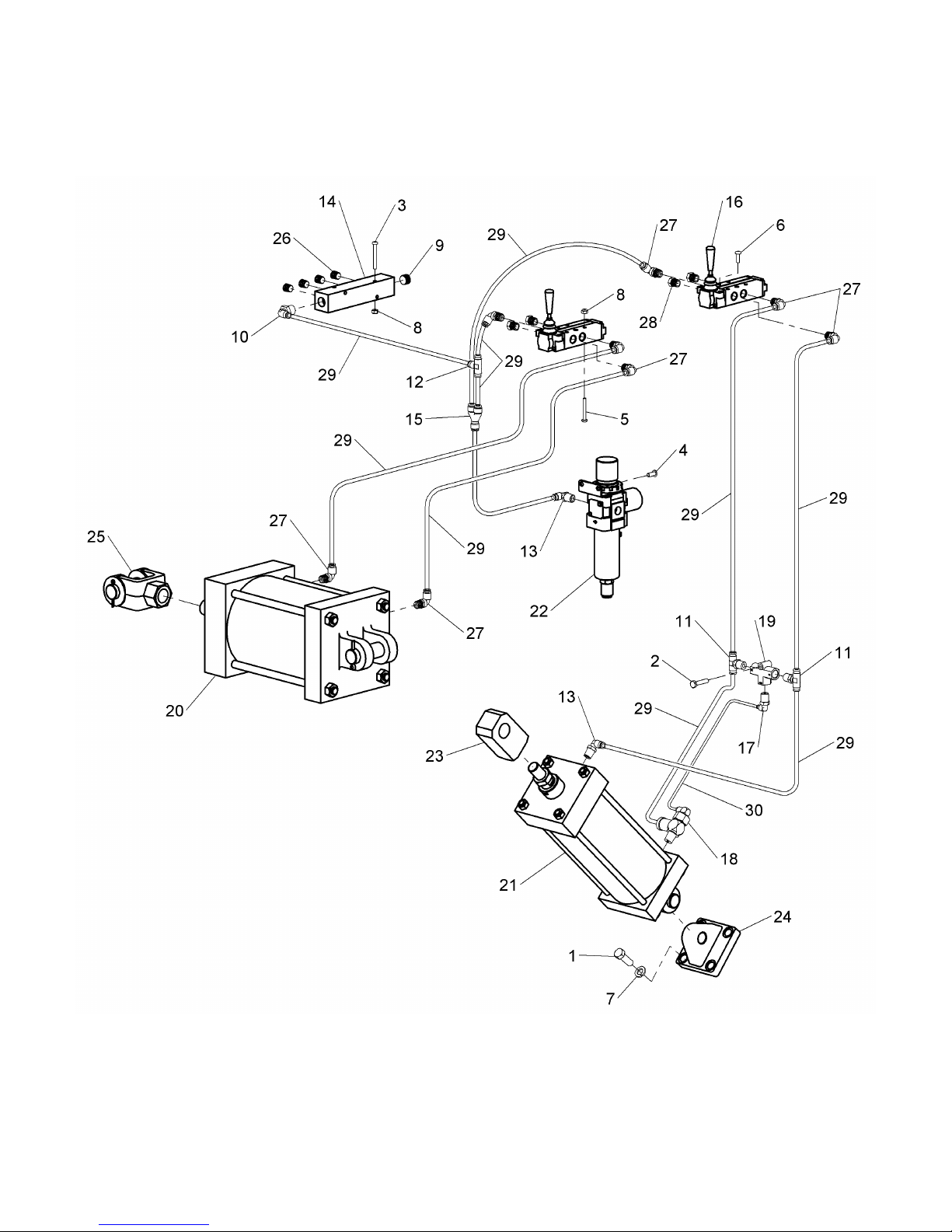
PNEUMATICS

10
PNEUMATICS
ITEM
PART NO.
DESCRIPTION
1
028-007
7/16-14 X 1-1/4 HEX HEAD SCREW
2
028-011
1/4-20 X 1-1/4 HEX HEAD SCREW
3
028-307
#10-24 X 1-3/4 MACHINE SCREW
4
50-0125
1/4-20 X 5/8 BUTTON HEAD SCREW
5
50-0178
#10-24 X 1-1/2 MACHINE SCREW
6
50-0186
M5 X 0.8 X 16 MACHINE SCREW
7
52-0057
7/16 SPLIT LOCK WASHER
8
055-127
#10-24 HEX LOCK NUT
9
60-0074
3/8 NPT PLUG
10
60-0120
3/8 NPT X 1/4 ELBOW
11
60-0164
1/4 NPT X 1/4 TEE
12
60-0171
1/4 UNION TEE
13
60-0172
1/4 NPT X 1/4 ELBOW - BRASS
14
60-0233
MANIFOLD
15
60-0307
1/4 WYE
16
60-0360
VALVE
17
60-0361
1/4 NPT X 5/32 ELBOW
18
60-0362
BLOCKING VALVE
19
60-0363
SHUTTLE VALVE
20
63-0033
SPREAD CYLINDER
21
63-0034
LIFT CYLINDER
22
64-0039
1/4 NPT FILTER/REGULATOR
23
69-0055
ROD EYE
24
69-0056
EYE BRACKET
25
69-0057
CLEVIS
26
096-004
1/4 NPT PLUG
27
096-342
1/4 NPT X 1/4 ELBOW
28
885-035
1/4 NPT BREATHER
29
D20-007
1/4 TUBE (YELLOW)
30
D20-042
5/32 TUBE (YELLOW)

11
COMMERCIAL WARRANTY
This product is warranted by BRANICK INDUSTRIES, INC. to the original user-owner against defective materials or
workmanship for a period of one year from the date of shipment. During the warranty period, at the discretion of Branick
management, if the product is found to be defective, it will be repaired or replaced without charge. For service, contact
Branick (800-437-4394) to obtain an RMA. Any product shipped to Branick must have an RMA and proof of original
shipment date. The repaired or replacement product will be returned with transportation charges prepaid by Branick.
This warranty does not cover defects in the product caused by ordinary wear and tear, abuse, misuse, overloading,
accident (including shipping damage), improper maintenance, alteration, or any other cause not the result of defective
materials or workmanship.
REPAIR OR REPLACEMENT IS THE EXCLUSIVE REMEDY FOR DEFECTIVE PRODUCT UNDER THIS WARRANTY.
THIS WARRANTY IS EXPRESSLY IN LIEU OF ALL OTHER WARRANTIES, INCLUDING ANY IMPLIED WARRANTY
OF MERCHANT ABILITY OR ANY IMPLIED WARRANTY OF FITNESS FOR A PARTICULAR PURPOSE OF THIS
PRODUCT. BRANICK INDUSTRIES, INC. SHALL NOT BE LIABLE FOR ANY CONSEQUENTIAL OR INCIDENTAL
DAMAGES.
BRANICK INDUSTRIES, INC. reserves the right to make changes in the design or construction of our products without
obligation to incorporate such changes in products already sold and without notice.
Service parts and regular repair service are available from authorized distributors of Branick products, or from:
BRANICK INDUSTRIES, INC.
4245 Main Ave.
Fargo, North Dakota 58103
Toll Free: 800-437-4394
www.branick.com
© Copyright 2018 by Branick Industries, Inc. Printed in U.S.A.
Table of contents


