BraunAbility Kit 6 User manual

EN Instructions for tting and use
Kit 6, Kit 7
User Manual

2Kit 6 and Kit 7
Thank you for choosing
Kit 6 or Kit 7
from BraunAbility!
The following manual is an important part of the product, providing
you with information on how to achieve maximum performance
and safe operation. Keep the manual in a safe place so that you can
refer to it when necessary.
If you have any questions about your equipment, please contact us.
Once again, thank you for placing your condence in our products!
Safe vehicle adaptation solutions
For your safety BraunAbility products are
designed and tested according to current
directives and standards.

Safety information
Fit and use
After care
Limitations of use
General guidance
Before installing and using the kits
Fitting the front wheelchair tie-down - Kit 6
Fitting the rear wheelchair tie-down - Kit 6
Fitting and using the occupant restraint - Kit 6 & Kit 7
Removing the occupant restraint - Kit 6 & Kit 7
Fitting the wheelchair tie-down - Kit 7
Equipment storage and maintenance
Warranty
4
6
8
10
12
14
16
17
19
19
3
Kit 6 and Kit 7
EN
Index
“Declaration of conformity” at the end of the manual.

Limitation of use
Safety information
The development of BraunAbility kits is a continuous process. Applications
are added on a regular basis. For more detail contact BraunAbility or look
on the BraunAbility website.
4Kit 6 and Kit 7

Kit 6
Kit 7
5
Kit 6 and Kit 7
EN
Safety information

General guidance
• Wheelchair Accessories that have not been approved by the Wheelchair Manufacturer must
be removed from the wheelchair and secured in the vehicle during transport to reduce the
potential for injury. Refer to ‘Instructions For Use in Transport’ provided with the wheelchair
or contact wheelchair manufacturer for further guidance.
• These wheelchair & occupant restraint kits comply with all applicable requirements of ISO
10542, including a 48km/h, 20g frontal impact test using a forward facing 85kg surrogate
wheelchair and an ATD (test dummy) with a mass of 76.3kg. The test dummy was restrained
by both a pelvic and upper-torso restraint. Use of a pelvic only belt may compromise the
performance of the WTORS system and should be avoided.
• If the installation is to be used with an occupant head rest anchored to the vehicle, then
a vehicle-anchored back rest must be provided to minimise rearward deection of the
wheelchair seatback, preventing neck injury.
• Regular inspection of all parts is recommended and the equipment should be used only if
all components are in good condition.
• Warning: protect webbing from contacting sharp edges and corners. Replace equipment if
the webbing does becomes cut, contaminated or frayed.
6Kit 6 and Kit 7

• Any restraints which have been subjected to a crash situation from which the vehicle must
be towed should, in the interest of safety, be replaced.
• Do not attempt to modify the equipment. For further advice on the installation and use of
this tie-down, please contact BraunAbility. Please read this manual fully before use.
• Avoid contact with corrosive liquids. Care should be taken to prevent contamination of the
webbing with polishes, oils and chemicals.
• The restraint kit anchorages should be installed by an experienced technician/vehicle
converter. Anchorages should not be installed into unsound materials such as corroded
metal, wood, plastic and bre glass panels, without additional and suitable reinforcement.
• The equipment has been tested in a conguration similar to that recommended by
BraunAbility, and any deviation from the recommendations here is the responsibility of the
installer/user. These instructions refer use with both BraunAbility rails and Solo anchors,
however the equipment may be used with any BraunAbility proprietary rail product.
7
Kit 6 and Kit 7
EN
Safety information

Before installing and using the wheelchair & occupant restraint kits
• Ensure that the wheelchair is correctly maintained and that the settings of any adjustable
parts are made according to ‘Instructions for Use in Transport’.
• Whenever possible remove any items of luggage etc that may be attached to the wheelchair
and secure or store separately during transport in order to reduce the potential for injury to
other passengers travelling in the vehicle.
• Extra care must be exercised when using vehicle boarding aids such as passenger lifts or
ramps during the loading process. Refer to ‘Instructions For Use’ for information on safe
slopes.
• Position the wheelchair facing forward - centrally in the designated region of the vehicle.
Ensure the wheelchair brakes are applied.
• To minimise the potential for head injuries in an impact, allow a clear space of at least 400
mm behind and 650 mm, (FCZ, front clear zone), in front of the head of the wheelchair
user, (Fig A). The shoulder belt anchorage must be roof or side-wall anchored at a height
level such that the belt webbing passes over the midpoint of the occupant shoulder and
at a height that is at or just above the level of the occupants shoulders so as not to impose
downward loads on the spine.
• A height provision (HHT) ranging from 1000mm to 1550mm should be made, depending
on the size of the passenger. There should also be 200 mm of clear space either side of
the wheelchair centre line. If these clear space dimensions cannot be provided then any
should be adequately padded and comply with impact performance requirements of
ECE Regulation 21 ‘FMVSS 201’. All vehicle padding should comply with the ammability
requirements of ECE Regulation 118 ‘FMVSS 302’.
Note: seated head
height (HHT) ranges
from as low as
1000mm for a 6-year-
old child to 1550mm
for a tall adult.
8Kit 6 and Kit 7

• Wheelchair users, their carers and family are advised to check vehicle
specications to ensure that sufcient oor space is available to
accommodate the wheelchair and tie-down system. These distances
are based upon the desire to maintain clear zones for potential head
excursions of occupants provided with both upper and lower torso
restraints.
• Users of heavy powered wheelchairs are also advised to check vehicle
carrying capacity. If in doubt consult the vehicle supplier for further
details.
• Any airbag, as tted to the vehicle, shall be used only as a supplementary
occupant restraint if designed to be used in combination with the Solar
Quattro and an appropriate occupant restraint.
• Installers of this tie-down should take note of any vehicle airbag position
when planning the installation. Airbags can cause serious injury if a
wheelchair-seated occupant is seated too close to an airbag position. If
in doubt contact the vehicle manufacturer or your National Automotive
Regulatory Body for advice. Figure A
9
Kit 6 and Kit 7
EN
Safety information

Fit and use
Fitting the front wheelchair tie-down
1. The rail will have been installed in the vehicle in accordance with our
own and the vehicle converter’s instruction. Position the wheelchair
within the vehicle as required.
2. Install the front tie-down ATF (aluminium track tting) into the front
rail by aligning the ATF feet with the cut-out sections of the rail, and
locate into the rail, (Fig 1).
3. Press down on the ribbed part of the ATF, (Fig 1A), and push rmly
towards the wheelchair until the yellow plunger drops and locks into
the rail.
4. Install the second front tie-down ATF in the same way, ensuring that
each tting is opposite each other, if using rail lengths which have
adjustability in ATF positioning.
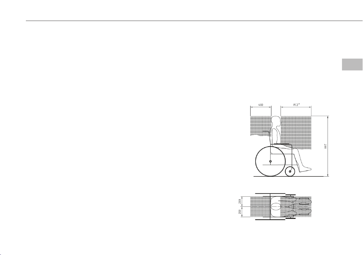
5. Press the red buckle button(s) to release the webbed tongue, extend
and pass around each of the front wheelchair frame tie-down points,
(Fig 2), (some wheelchairs will indicate these tie-down positions, Fig
3). Reconnect the tongue back into the buckle, creating an angle of
around 40 to 60° within the front view zone, (Fig 4).
6. Release the wheelchair brakes and pull back to tension the front tie-
downs. Re-apply the brakes. The rear tie-downs should now be tted.
Removing the tie-downs
IMPORTANT: First remove the rear
tie-downs, as instructed on pages
12 and 13.
1. Once the rear tie-downs have
been removed, press the red
buckle release button to release
the webbed tongue. Pass back
through the front wheelchair
frame tie-down points and
return the tongue to the buckle.
2. Lift the ATF yellow plunger fully
and slide back away from the
wheelchair to align the ATF feet
with the rail cut-outs, lift away
from the rail.
Note: in an emergency, the front
tie-downs can be released from
the wheelchair without the need to
slacken the rears by simply pressing
the red buckle release button.
Fitting and using the wheelchair and occupant restraint - Kit 6
10 Kit 6 and Kit 7

Figure 3
Figure 2
Figure 1
A
Figure 4
11
Kit 6 and Kit 7
EN
Fit and use

Fit and use
Fitting the rear wheelchair tie-down
1. Ensure that the rear Quattro restraints are tted with the karabiner gates
facing outwards (Fig 5A).
2. Install the Quattro restraints into the rear rail, in the same way as the
fronts.
3. Press the yellow Quattro release button(s), (Fig 5B) to extend the webbing
and attach the karabiner around the wheelchair main frame. (Some
wheelchairs will indicate this rear frame tie down position, Fig 6).
4. Press each Quattro release button once again to take up the slack in the
webbing and create an angle of around 30 to 45° and within the rear view
zone, (Fig 7).
5. Final tensioning is achieved by turning the tensioning handles until the
webbing is equally taut on each side (Fig 5C).
6. The occupant restraint must now be tted.
Removing the tie-downs
1. Release the tension in the rears
by pressing the yellow button
and extending the webbing
to allow the karabiners to be
removed from the wheelchair
frame. If the webbing is
particularly tight, it may be
necessary to slightly ’tension’
the webbing with the hand
wheel, whilst pressing the
yellow button, to remove the
webbing lock on the Quattro.
2. Remove each Quattro ATF from
the rail by simultaneously lifting
the yellow plunger and sliding
the tting back until the ATF
feet align with the cut outs in
the rail.
3. Now move to the front of the
wheelchair and release the tie-
downs as instructed on pages 10
and 11.
Fitting and using the wheelchair and occupant restraint - Kit 6
12 Kit 6 and Kit 7

Figure 6
A
Figure 5
C
B
Figure 7
13
Kit 6 and Kit 7
EN
Fit and use

Fitting and using the wheelchair and occupant restraint - Kit 6 & Kit 7
Fit and use
Fitting the occupant restraint
• BraunAbility recommends the use of a 3 point occupant
restraint system to provide greater protection in case of
an impact. However we also recognise that some vehicle
layout/designs or specic postural or medical conditions
do not allow that style of seatbelts to be used easily.
• This system is not ISO 10542 compliant if used in 2 point
conguration.
1. Position the occupant restraint behind the wheelchair tie-
down, with reel housing (Fig 12A) on the window side of
the vehicle and reversible/xed stalk (Fig 12B) on the aisle
2. Fit the occupant restraint track tting into the rail ATF
(aluminium track tting) by aligning the ATF feet with the
cut-out sections of the rail. Locate into the rail, (Fig 2).
3. Press on the ribbed part of the ATF, (Fig 2A), and push
rmly towards the wheelchair until the yellow plunger
drops and locks into the rail.
4. Position the third point xing into the cant rail, (Fig 8), so
that it is vertically above the inertia reel casing xed onto
the oor xing. Unfasten the tongue and buckle.
5. Pull the black webbing upwards and unfasten the tongue
from the grey webbing buckle.
6. Position the black webbing to form the lap belt and insert
the tongue into the buckle stalk, (Fig 9).
• Before tting the occupant restraint, ensure that the
reversible stalk orange button is facing outside in relation
to the wheelchair. If the reversible stalk orange button faces
inside, turn the stalk 180º to sit in the right position.
• In accordance with International regulations, standard
BraunAbility occupant restraints are designed to be used
for passengers weighing 22kg or above. If the passenger
weighs less than 22kg, BraunAbility recommends that a
suitable, and appropriately tested child restraint seat is
used. This may involve a secondary seat belt restraint as
recommended by the original seat manufacturer.
7. Ensure that the lap belt lays low on the pelvis of the
occupant, running as close as possible over the hips on both
sides.
8. Remove the black plastic cover on the grey shoulder belt
tongue and t into the third point xing. Position the grey
webbing to form the shoulder belt and insert the buckle
into the tongue.
9. Adjust the height of the shoulder belt to clear occupant’s
shoulder by approximately 25mm - 1 inch, (Fig 10).
10. The lap belt anchor points should be positioned to achieve
belt angles of 30° or more to the horizontal and preferably
between 45° and 75° in order to t low across the pelvis
reducing the possibility of the belt loading the abdomen,
(Fig 11). The pelvic restraint is designed to bear upon the
bony structure of the body and should be worn low across
the front of the pelvis with any junctions between the pelvic
and shoulder restraints located near the wearers hips.
14 Kit 6 and Kit 7

A
A
B
Figure 10
Figure 9
Figure 8
Figure 11
Figure 12
15
Kit 6 and Kit 7
EN
Fit and use

Removing the occupant restraint - Kit 6 & 7
Fit and use
1. Release the grey shoulder belt from the lap belt section, from the third point xing and
carefully allow the shoulder belt to return to the retractor.
2. Disconnect the black lap belt from the buckle stalk on the aise side and carefully allow the
lap belt webbing to return to the retractor.
3. Connect the shoulder belt buckle to the lap belt tongue above the opening of the retractor
box.
4. Before releasing the restraint, ensure the wheelchair brakes are applied.
16 Kit 6 and Kit 7

Fit and use
Fitting the wheelchair tie-down
1. Ensure that the front Quattro restraints are tted with the karabiner gates
facing outwards (Fig 5A).
2. Install the front tie-down ATF (aluminium track tting) into the front rail
by aligning the ATF feet with the cut-out sections of the rail, and locate
into the rail, (Fig 13).
3. Press the yellow Quattro release button(s), (Fig 5B) to extend the webbing
and attach the karabiner around the wheelchair main frame. (Some
wheelchairs will indicate this front frame tie-down position, Fig 3).
4. Press each Quattro release button once again to take up the slack in the
webbing and create an angle of around 30 to 45° and within the rear view
zone, (Fig 4).
5. Press the yellow button(s) again to remove the webbing slack.
6. Ensure that each front Quattro webbing is approximately the same
length.
7. The rear tie downs should now be installed as instructed on pages 12 &
13.
8. The occupant restraint must now be tted as instructed on pages 14 &
15.
Removing the tie-downs
IMPORTANT: First remove the
occupant restraint as instructed on
page 16, then the rear tie-downs, as
instructed on pages 12-13.
1. Release the tension in the
front tie-downs by pressing the
yellow button and extending
the webbing to allow the
karabiners to be removed from
the wheelchair frame. If the
webbing is particularly tight,
it may be necessary to slightly
’tension’ the webbing with the
hand wheel, whilst pressing the
yellow button, to remove the
webbing lock on the Quattro.
2. Remove each Quattro ATF from
the rail by simultaneously lifting
the yellow plunger and sliding
the tting back until the ATF
feet align with the cut outs in
the rail.
3. Lift the Quattro clear of the rail
and store safely.
Fitting and using the wheelchair and occupant restraint - Kit 7
17
Kit 6 and Kit 7
EN
Fit and use

Figure 3
A
Figure 5
Figure 4
Figure 13
A
B
18 Kit 6 and Kit 7

Equipment storage and maintenance
After care
• Store the restraint safely off the oor to avoid damage and
ensure that it cannot become a projectile in an accident. This
can be achieved by using wall mounted storage bag such as
SLR111.
• Regularly inspect the BraunAbility Kit for damage, wear
or malfunction. If any problems are identied replace it
immediately.
• All webbings and components can be cleaned as necessary, but
care should be taken to prevent contamination of the webbings
with polishes, oils and chemicals.
• To clean the straps use warm soapy water and a clean soft cloth.
Rinse with clear water and allow to air dry. To disinfect, use a
mild spray disinfectant and do not use products containing
bleach. Important: when cleaning or disinfecting, do not
immerse buckles, karabiners or Solo ttings in the disinfectant
or water.
• If the vehicle is involved in an accident when any restraints are
deployed, remove them from service and replace immediately. If
in doubt please contact BraunAbility.
Warranty
BraunAbility products are
extensively tested using
BraunAbility anchorage systems,
and our full warranty normally
only applies to BraunAbility
equipment when used
with BraunAbility branded
anchorages or as instructed.
BraunAbility have also
participated in test programs
with other manufacturers
anchorage products and
will support warranty on the
BraunAbility products when
used in conjunction with
such jointly tested systems.
For further details on specic
applications please contact the
Sales Ofce. In other situations,
using BraunAbility products,
for which BraunAbility has
not participated in a joint test
program, a limited BraunAbility
warranty will apply.
19
Kit 6 and Kit 7
EN
After care

Declaration of conformity
Conforms to following directives
standards and regulations /
214/2014/EU Paragraphs 2.3.1 and 2.3.2
ISO 10542:2012
RESNA WC-4 2012 Section 18
2007/46/EC
BraunAbility UK Ltd, Martock 19 February 2019
Rob Butcher
Director of Engineering
Manufacturer /
BraunAbility UK Ltd.
Unwin House
The Horseshoe Coat Road
Martock, Somerset, UK
Phone: +44 1935 827740
E-mail: sales.uk@braunability.eu
www.braunability.eu
Declares that the product /
Kit 6, Kit 7
This manual suits for next models
1
Table of contents
Other BraunAbility Automobile Accessories manuals

BraunAbility
BraunAbility ULB User manual

BraunAbility
BraunAbility Foldout Ramp Manual

BraunAbility
BraunAbility Simple Stow Infloor User manual

BraunAbility
BraunAbility Carolock User manual

BraunAbility
BraunAbility Pedal Extension Mini User manual

BraunAbility
BraunAbility Simple Stow User manual

BraunAbility
BraunAbility EntervanII Application guide

BraunAbility
BraunAbility Entervan XT Manual

BraunAbility
BraunAbility UVL Series User guide

BraunAbility
BraunAbility Rampvan Manual